steering SSANGYONG RODIUS 2005 User Guide
[x] Cancel search | Manufacturer: SSANGYONG, Model Year: 2005, Model line: RODIUS, Model: SSANGYONG RODIUS 2005Pages: 502, PDF Size: 70.43 MB
Page 279 of 502

0-7
POWER STEERING SYSTEM
RODIUS 2005.07
4610-00
2. POWER STEERING GEAR BOX ASSEMBLY
The power steering gear consists of power cylinder and control valve.
The power cylinder has cylinder, piston and piston rod. The control valve directs the oil to one
end face of the piston to enhance the steering force.
The control valve controls the directions and operations of power cylinder.
Additionally, the safety check valve is installed so that the system can be operated manually
when the system is defective.
Page 280 of 502

0-8
RODIUS 2005.07
4610-00
POWER STEERING SYSTEM
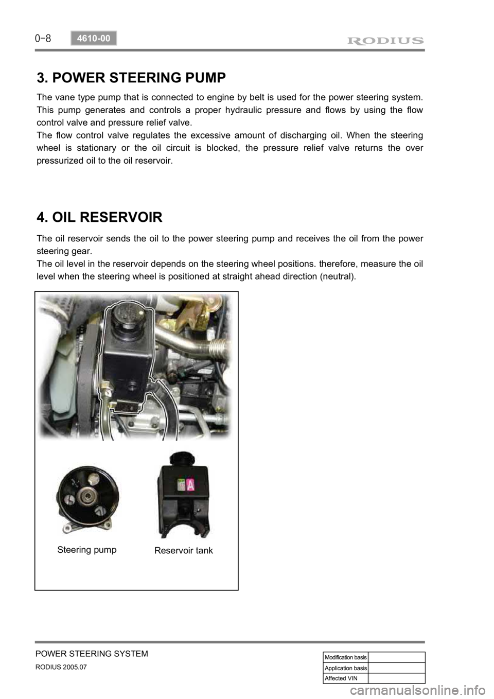
3. POWER STEERING PUMP
The vane type pump that is connected to engine by belt is used for the power steering system.
This pump generates and controls a proper hydraulic pressure and flows by using the flow
control valve and pressure relief valve.
The flow control valve regulates the excessive amount of discharging oil. When the steering
wheel is stationary or the oil circuit is blocked, the pressure relief valve returns the ove
r
pressurized oil to the oil reservoir.
4. OIL RESERVOIR
The oil reservoir sends the oil to the power steering pump and receives the oil from the power
steering gear.
The oil level in the reservoir depends on the steering wheel positions. therefore, measure the oil
level when the steering wheel is positioned at straight ahead direction (neutral).
Steering pump Reservoir tank
Page 285 of 502

0-7
WHEEL
RODIUS 2005.07
4710-09
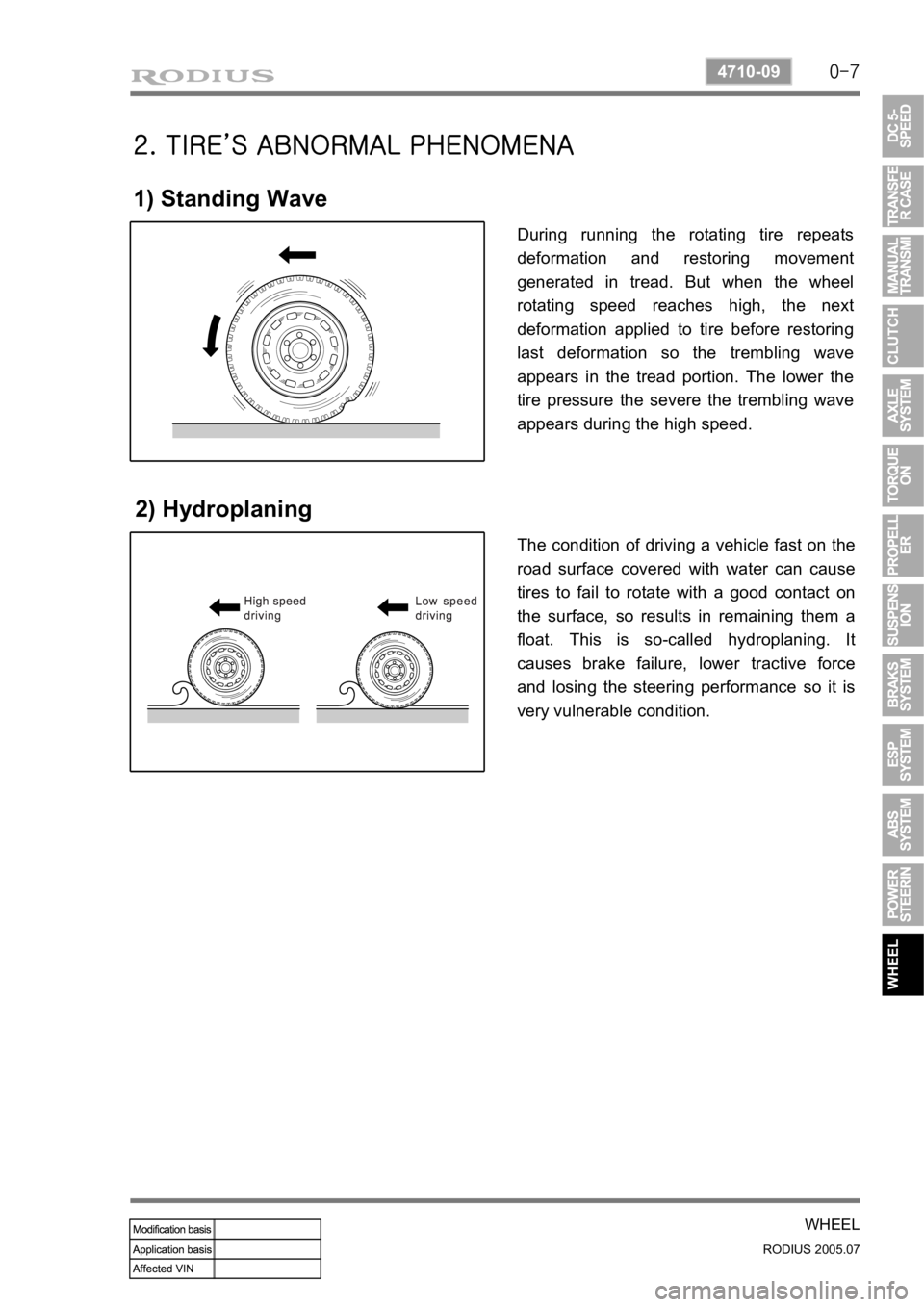
2. TIRE’S ABNORMAL PHENOMENA
1) Standing Wave
2) Hydroplaning
During running the rotating tire repeats
deformation and restoring movement
generated in tread. But when the wheel
rotating speed reaches high, the next
deformation applied to tire before restoring
last deformation so the trembling wave
appears in the tread portion. The lower the
tire pressure the severe the trembling wave
appears during the high speed.
The condition of driving a vehicle fast on the
road surface covered with water can cause
tires to fail to rotate with a good contact on
the surface, so results in remaining them a
float. This is so-called hydroplaning. It
causes brake failure, lower tractive force
and losing the steering performance so it is
very vulnerable condition.
Page 286 of 502

0-8
RODIUS 2005.07
4710-09
WHEEL
3. WHEEL ALIGNMENT
The first responsibility of engineering is to design safe steering and suspension systems. Each
component must be strong enough to with stand and absorb extreme punishment.
Both the steering system and the front and the rear suspension must function geometrically
with the body mass.
The steering and suspension systems require that the front wheels self-return and that the tire
rolling effort and the road friction be held to a negligible force in order to allow the customer to
direct the vehicle with the least effort and the most comfort.
A complete wheel alignment check should include measurements of the rear toe and camber.
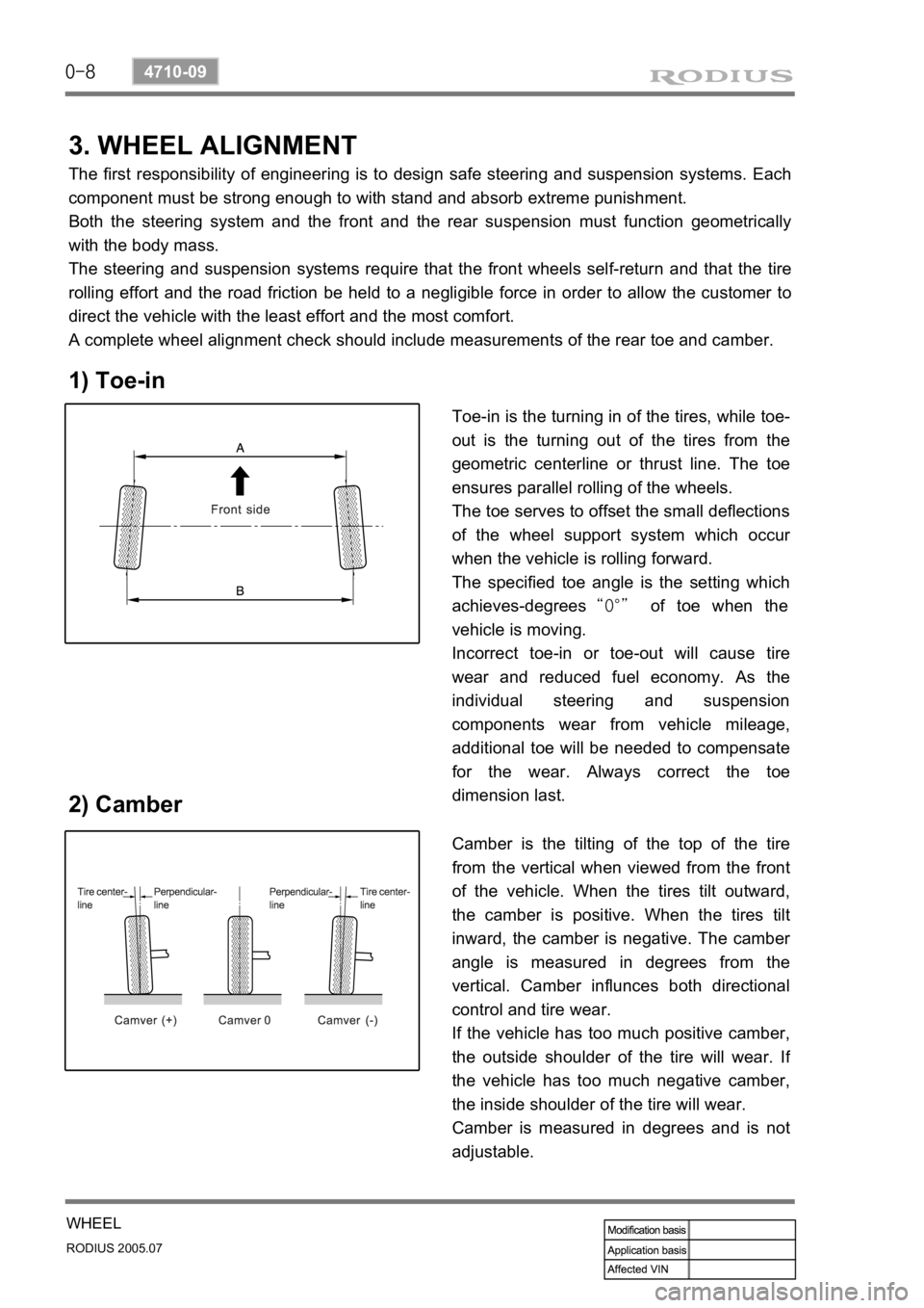
1) Toe-in
2) Camber
Toe-in is the turning in of the tires, while toe-
out is the turning out of the tires from the
geometric centerline or thrust line. The toe
ensures parallel rolling of the wheels.
The toe serves to offset the small deflections
of the wheel support system which occu
r
when the vehicle is rolling forward.
The specified toe angle is the setting which
achieves-degrees “0°” of toe when the
vehicle is moving.
Incorrect toe-in or toe-out will cause tire
wear and reduced fuel economy. As the
individual steering and suspension
components wear from vehicle mileage,
additional toe will be needed to compensate
for the wear. Always correct the toe
dimension last.
Camber is the tilting of the top of the tire
from the vertical when viewed from the front
of the vehicle. When the tires tilt outward,
the camber is positive. When the tires tilt
inward, the camber is negative. The cambe
r
angle is measured in degrees from the
vertical. Camber influnces both directional
control and tire wear.
If the vehicle has too much positive camber,
the outside shoulder of the tire will wear. I
f
the vehicle has too much negative camber,
the inside shoulder of the tire will wear.
Camber is measured in degrees and is not
adjustable.
Page 287 of 502

0-9
WHEEL
RODIUS 2005.07
4710-09
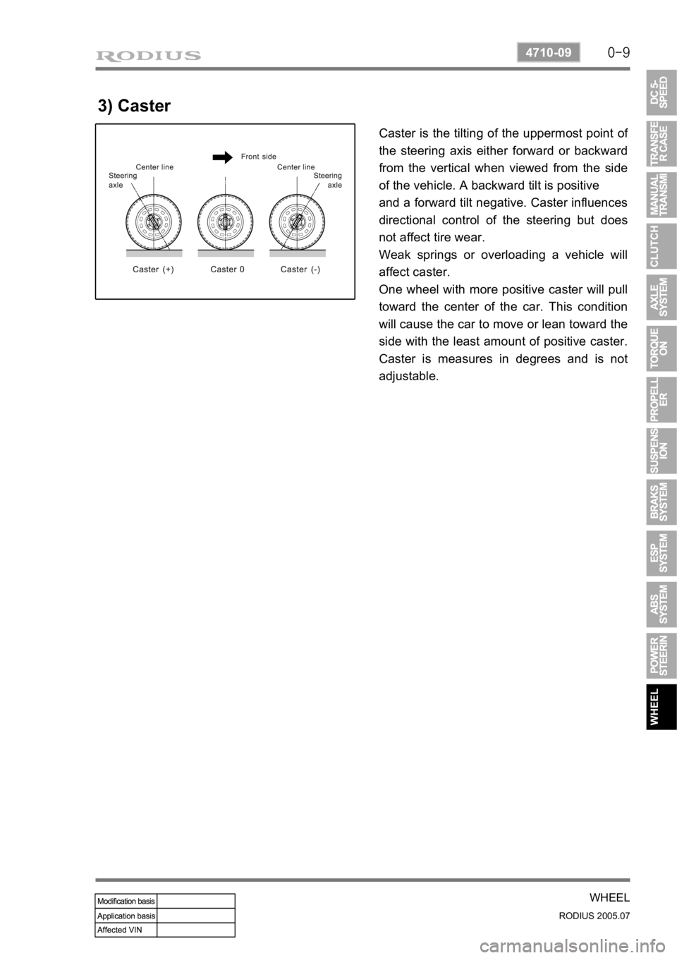
3) Caster
Caster is the tilting of the uppermost point of
the steering axis either forward or backward
from the vertical when viewed from the side
of the vehicle. A backward tilt is positive
and a forward tilt negative. Caster influences
directional control of the steering but does
not affect tire wear.
Weak springs or overloading a vehicle will
affect caster.
One wheel with more positive caster will pull
toward the center of the car. This condition
will cause the car to move or lean toward the
side with the least amount of positive caster.
Caster is measures in degrees and is not
adjustable.
Page 295 of 502

0-8
RODIUS 2005.07
0000-00
ELECTRIC GENERAL
3. SWITCHES IN PASSENGER COMPARTMENT
Audio remote control switch on the steering wheel
Page 443 of 502

0-6
RODIUS 2005.07
8810-01
AIR BAG SYSTEM
3. AIRBAG FUNCTION DESCRIPTION
1) Bag (Cushion)
The airbag system performance is influenced on the cushion size, shape and position.
The cushion strength is a important parameter on the impact absorb effect.
Therefore, the control of the airbag performance depends on cushion size, shape, inflato
r
characteristic and vent hole size for the gas discharge.
The cushion’s material and folding function to control the cushion deployment
direction and the performance to protect passenger’s face. ·
·
·
·
2) Airbag Module
The driver airbag module is under the center pad of the steering wheel.
The passenger airbag module is installed in the instrument panel at passenger side.
The driver and passenger side airbag is inside each seat.
3) Module Cover/Housing
It is a type of a container that includes the cushion and the inflator.
The module housing functions to deliver the reaction force between the body structure and
the airbag (The airbag reaction is absorbed generally to the steering wheel or instrument
panel).
The module cover must be considered in a viewpoint of protection between exterior,
internal units and cushion. Also the module cover should be designed not to cause any
personal injury for deployment. ·
·
·
Do not disassemble the airbag module because unintentional deployment of the airbags
resulting from any damage or interference of the module can cause injury. -
Page 445 of 502

0-8
RODIUS 2005.07
8810-01
AIR BAG SYSTEM
6) Contact Coil
The contact coil is installed between the steering wheel and the steering column and contains a
coil that enables to contact electrically between the airbag wiring harness, the driver airbag
module and the horn switch.
Turning the steering wheel more than three and onequarter turns may damage the clock
spring. The contact coil should never be disassembled and must be replaced if the airbag
have been deployed. -
Turn the label of the clock spring clockwise to lock and turn the label of the clock spring
counterclockwise approximately 2.9 ± 0.2 turns to the neutral positions with the front
wheels ahead.
Align the pointed marks “43”. -
7) Accelometer Sensor
The accelerometer sensor electronically represents the acceleration or deceleration of the
vehicle during a frontal impact.
In this electronic representation, the electrical signal is proportional to the acceleration o
r
deceleration of the vehicle.
8) Safety Sensor
The safety sensor is safety device made up of a dualcontact, electro-mechanical switch that:
Acts independently of the electronic components.
Connects the acceleration sensor in series in order to make up for the weak points in the
current electronic sensor. 1.
2.