SSANGYONG RODIUS 2005 Service Manual
Manufacturer: SSANGYONG, Model Year: 2005, Model line: RODIUS, Model: SSANGYONG RODIUS 2005Pages: 502, PDF Size: 70.43 MB
Page 121 of 502

07-5
ENGINE COOLING SYSTEM
RODIUS 2005.07
2110-01
1. COMPONENTS LOCATOR
Radiator
Electric fan
Shroud
Deaeration tube
Clamp
Deaeration hose (radiator)
Electric fan mounting bracket
Bolt (M6, 8 pieces)
Bolt (M6, 4 pieces) 1.
2.
3.
4.
5.
6.
7.
8.
9. Bolt (M6, 4 pieces)
Upper radiator insulator
Lower radiator insulator
Plate
Clip
Inlet hose
Outlet hose
3 way hose
Deaeration hose (reserver tank) 10.
11.
12.
13.
14.
15.
16.
17.
18. Clamp
Clamp
Make up hose holder
Reserver tank
Bolt (M6, 2 piece)
Cooling fan
Viscous clutch
Bolt (M6, 1 piece)
Bolt (M6, 3 piece) 19.
20.
21.
22.
23.
24.
25.
26.
27.
Page 122 of 502

07-6
RODIUS 2005.07
2110-01
ENGINE COOLING SYSTEM
2. DESCRIPTION AND OPERATION
1) GENERAL DESCRIPTION
The cooling system maintains the engine temperature at an efficient level during all engine
operating conditions. When the engine is cold, the cooling system cools the engine slowly o
r
not at all. This slow cooling of the engine allows the engine to warm up quickly.
The cooling system includes a radiator and recovery subsystem, cooling fans, a thermostat and
housing, a water pump, and a water pump drive belt. The timing belt drives the water pump.
All components must function properly for the cooling system to operation. The water pump
draws the coolant from the radiator. The coolant then circulates through water jackets in the
engine block, the intake manifold, and the cylinder head. When the coolant reaches the
operating
temperature of the thermostat, the thermostat opens. The coolant then goes back to the
radiator where it cools.
This system directs some coolant through the hoses to the heat core. This provides for heating
and defrosting. The coolant reservoir is connected to the radiator to recover the coolant
displaced by expansion from the high temperatures. The coolant reservoir maintains the correct
coolant level.
The cooling system for this vehicle has no radiator cap or filler neck. The coolant is added to
the cooling system through the coolant reservoir.
2) RADIATOR
This vehicle has a lightweight tube-and-fin aluminum radiator. Plastic tanks are mounted on the
upper and the lower sides of the radiator core.
On vehicles equipped with automatic transaxles, the transaxle fluid cooler lines run through the
radiator tank. A radiator drain plug is on this radiator.
To drain the cooling system, open the drain plug.
Page 123 of 502

07-7
ENGINE COOLING SYSTEM
RODIUS 2005.07
2110-01
3) COOLANT RESERVOIR
The coolant reservoir is a transparent plastic reservoir, similar to the windshield washer
reservoir.
The coolant reservoir is connected to the radiator by a hose and to the engine cooling system
by another hose. As the vehicle is driven, the engine coolant heats and expands. The portion o
f
the engine coolant displaced by this expansion flows from the radiator and the engine into the
coolant reservoir. The air trapped in the radiator and the engine is degassed into the coolant
reservoir.
When the engine stops, the engine coolant cools and contracts. The displaced engine coolant
is then drawn back into the radiator and the engine. This keeps the radiator filled with the
coolant to the desired level at all times and increases the cooling efficiency.
Maintain the coolant level between the MIN and MAX marks on the coolant reservoir when the
system is cold.
4) THERMOSTAT
A wax pellet-type thermostat controls the flow of the engine coolant through the engine cooling
system. The thermostat is mounted in the thermostat housing to the front of the cylinder head.
The thermostat stops the flow of the engine coolant from the engine to the radiator to provide
faster warm-up, and to regulate the coolant temperature. The thermostat remains closed while
the engine coolant is cold, preventing circulation of the engine coolant through the radiator.
At
this point, the engine coolant is allowed to circulate only throughout the heater core to warm it
quickly and evenly.
As the engine warms, the thermostat opens. This allows the engine coolant to flow through the
radiator where the heat is dissipated. This opening and closing of the thermostat permits
enough engine coolant to enter the radiator to keep the engine within proper engine
temperature operating limits.
The wax pellet in the thermostat is hermetically sealed in a metal case. The wax element of the
thermostat expands when it is heated and contracts when it is cooled.
As the vehicle is driven and the engine warms, the engine coolant temperature increases.
When the engine coolant reaches a specified temperature, the wax pellet element in the
thermostat expands and exerts pressure against the metal case, forcing the valve open. This
allows the engine coolant to flow through the engine cooling system and cool the engine.
As the wax pellet cools, the contraction allows a spring to close the valve.
The thermostat begins to open at 82°C (180°F) and is fully open at 95°C (203°F). The
thermostat closes at 80°C (176°F).
Page 124 of 502

07-8
RODIUS 2005.07
2110-01
ENGINE COOLING SYSTEM
5) WATER PUMP
The belt-driven centrifugal water pump consists of an impeller, a drive shaft, and a belt pulley.
The impeller is supported by a completely sealed bearing.
The water pump is serviced as an assembly and, therefore, cannot be disassembled.
6) ELECTRIC COOLING FAN
Keep hands, tools, and clothing away from the engine cooling fans to help prevent
personal injury. This fan is electric and can turn on even when the engine is not running. -
f a fan blade is bent or damaged in any way, no attempt should be made to repair or reuse
the damaged part.
A bent or damaged fan assembly should always be replaced with a new one to prevent
possible injury. -
The cooling fans are mounted behind the radiator in the engine compartment. The electric
cooling fans increase the flow of air across the radiator fins and across the condenser on ai
r
conditioned (A/C)-equipped vehicles.
This helps to speed cooling when the vehicle is at idle or moving at low speeds.
All models have two fans. The main fan is 320 mm (12.6 inches) in diameter with seven blades
to aid the airflow through the radiator and the condenser. An electric motor attached to the
radiator support drives the fan. The auxiliary fan is 320 mm (12.6 inches) in diameter.
7) A/C OFF OR NON-AC MODEL
The cooling fans are actuated by the engine control module (ECM) using a low-speed
cooling fan relay, a high-speed cooling fan relay and a cooling fan motor relay.
The ECM will turn the cooling fans on at low speed when the coolant temperature reaches
95°C (203°F) and at high speed when the coolant temperature reaches 105°C (221°F).
The ECM will change the cooling fans from high peed to low speed at 100°C (212°F)
and will turn the cooling fans off at 90°C (194°F). ·
·
·
Page 125 of 502

07-9
ENGINE COOLING SYSTEM
RODIUS 2005.07
2110-01
8) A/C ON
The ECM will turn the cooling fans on at low speed when the A/C system is on. The ECM
will change to high speed when the high side A/C pressure reaches 1860 kPa (269.8 psi).
The cooling fans will return to low speed when the high side A/C pressure reaches 1378 kPa
(199.8 psi). ·
·
9) ENGINE COOLANT TEMPERATURE SENSOR
The Engine Coolant Temperature (ECT) sensor uses a temperature to control the signal
voltage to the Engine Control Module (ECM).
10) COOLANT TEMPERATURE GAUGE
The coolant temperature gauge controls the instrument panel temperature indicator. The
coolant temperature gauge is located with ECT sensor.
Page 126 of 502

04-3
ENGINE INTAKE SYSTEM
RODIUS 2005.07
1715-01
0000ENGINE INTAKE
1. FASTENER TIGHTENING SPECIFICATIONS
Page 127 of 502

04-4
RODIUS 2005.07
1715-01
ENGINE INTAKE SYSTEM
1. AIR CLEANER AND INTAKE AIR DUCT
▶ Specifications
Page 128 of 502

04-5
ENGINE INTAKE SYSTEM
RODIUS 2005.07
1715-01
2. RESONANCE FLAP
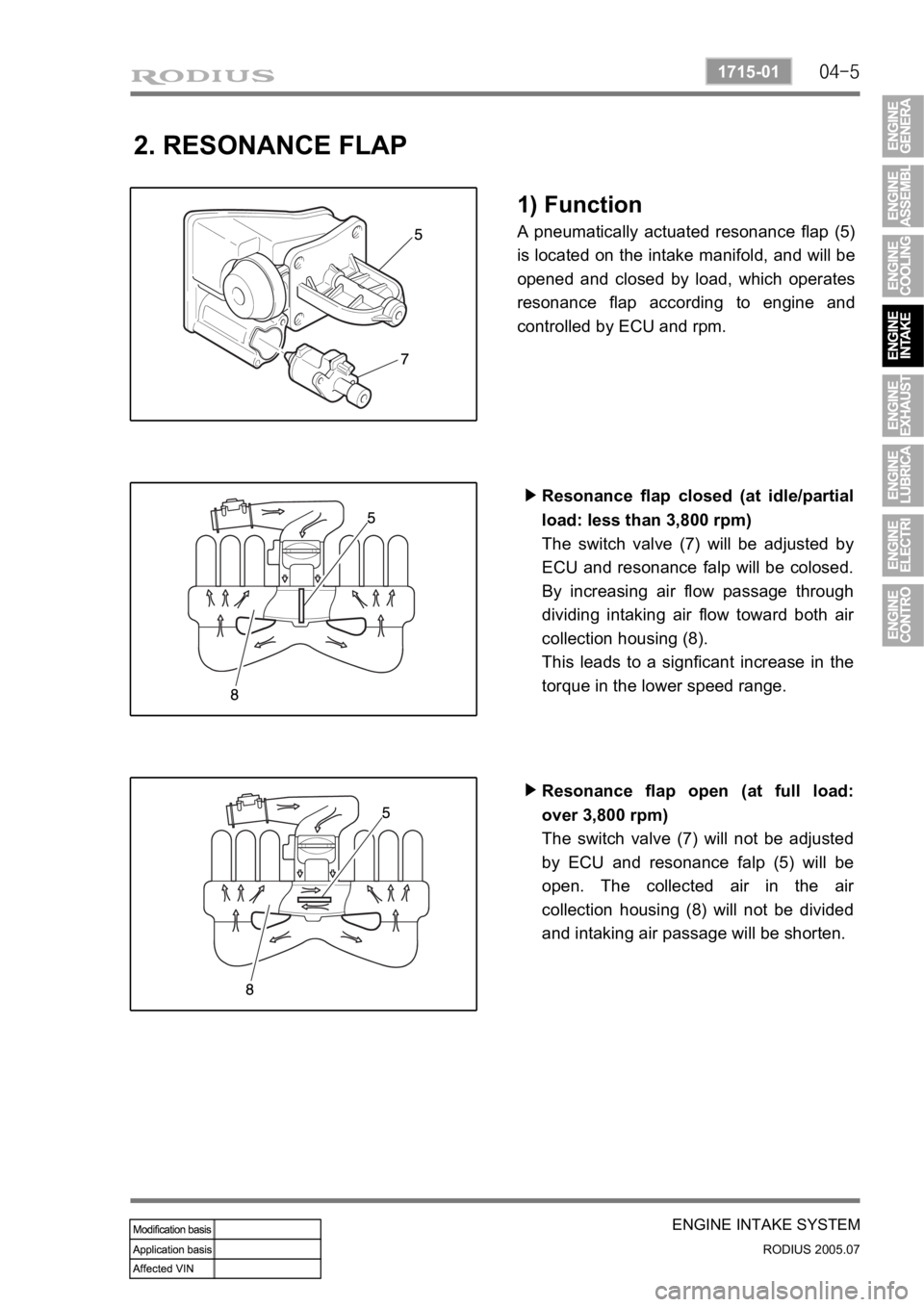
1) Function
A pneumatically actuated resonance flap (5)
is located on the intake manifold, and will be
opened and closed by load, which operates
resonance flap according to engine and
controlled by ECU and rpm.
Resonance flap closed (at idle/partial
load: less than 3,800 rpm)
The switch valve (7) will be adjusted by
ECU and resonance falp will be colosed.
By increasing air flow passage through
dividing intaking air flow toward both ai
r
collection housing (8).
This leads to a signficant increase in the
torque in the lower speed range. ▶
Resonance flap open (at full load:
over 3,800 rpm)
The switch valve (7) will not be adjusted
by ECU and resonance falp (5) will be
open. The collected air in the ai
r
collection housing (8) will not be divided
and intaking air passage will be shorten. ▶
Page 129 of 502

05-3
ENGINE EXHAUST SYSTEM
RODIUS 2005.07
2411-01
0000ENGINE EXHAUST
1. FASTENER TIGHTENING SPECIFICATIONS
Page 130 of 502

05-4
RODIUS 2005.07
2411-01
ENGINE EXHAUST SYSTEM
1. EXHAUST SYSTEM
When you are inspecting or replacing exhaust system components, make sure there is
adequate clearance from all points on the underbody to avoid possible overheating of the
floor panel and possible damage to the passenger compartment insulation and trim
materials. -
Check the complete exhaust system and the nearby body areas and trunk lid for broken,
damaged, missing or mispositioned parts, open seams, holes, loose connections, or othe
r
deterioration which could permit exhaust fumes to seep into the trunk may be an indication of a
problem in one of these areas. Any defects should be corrected immediately.
2. MUFFLER
Aside from the exhaust manifold connection, the exhaust system uses a flange and seal joint
design rather than a slip joint coupling design with clamp and U-bolts. If hole, open seams, o
r
any deterioration is discovered upon inspection of the front muffler and pipe assembly, the
complete assembly should be replace, the complete assembly should be replaced. The same
procedure is applicable to the rear muffler assembly.
Heat shields for the front and rear muffler assembly and catalytic converter protect the vehicle
and the environment from the high temperatures that the exhaust system develops.
3. CATALYTIC CONVERTER
When jacking or lifting the vehicle from the body side rails, be certain that the lift pads do
not contact the catalytic converter, as this could damage the catalytic converter. -
Use of anything other than unleaded fuel will damage the catalyst in the catalytic converter. -
The catalytic converter are emission-control devices added to the exhaust system to reduce
pollutants from the exhaust pipes.
The oxidation catalyst is coated with a catalytic material containing platinum and palladium,
which reduces levels of hydrocarbon (HC) and carbon monoxide (CO) from the exhaust gas.
The three-way catalyst has coatings which contain platinum and rhodium, which additionally
lower the levels of oxides of nitrogen (NOx).