engine SSANGYONG RODIUS 2005 Workshop Manual
[x] Cancel search | Manufacturer: SSANGYONG, Model Year: 2005, Model line: RODIUS, Model: SSANGYONG RODIUS 2005Pages: 502, PDF Size: 70.43 MB
Page 151 of 502

09-5
ENGINE CONTROL SYSTEM
RODIUS 2005.07
0452-01
2) Fastener Tightening Specifications
Page 152 of 502

09-6
RODIUS 2005.07
0452-01
ENGINE CONTROL SYSTEM
3) Fuel System Specification
Use Only Unleaded Fuel Rated at 89 Octane or Higher ▶
Fuel quality and additives contained in fuel have a significant effect on power output, drivability,
and life of theengine.
Fuel with too low an octane number can cause engine knock.
Use of fuel with an octane number lower than 89 may damage engine and exhaust
system.
To prevent accidental use of leaded fuel, the nozzles for leaded fuel are larger, and will
not fit the fuel filler neck of your vehicle. -
-
Do Not Use Methanol ▶
Fuels containing methanol (wood alcohol) should not be used in vehicle.
This type of fuel can reduce vehicle performance and damage components of the fuel system.
Use of methanol may damage the fuel sys-tem. -
For safety reasons (particularly when using noncommercial fueling systems) fuel containers,
pumps and hoses must be properly earthed.
Static electricity build up can occur under certain atmospheric and fuel flow conditions i
f
unearthed hoses, particularly plastic, are fitted to the fuel-dispensing pump.
It is therefore recommended that earthed pumps with integrally earthed hoses be used, and
that storage containers be properly earthed during all noncommercial fueling operations.Vehicle Fueling from Drums or Storage Containers ▶
Page 153 of 502

09-7
ENGINE CONTROL SYSTEM
RODIUS 2005.07
0452-01
4) Temperature Vs Resistance
Page 154 of 502
09-8
RODIUS 2005.07
0452-01
ENGINE CONTROL SYSTEM
1. IGNITION SYSTEM
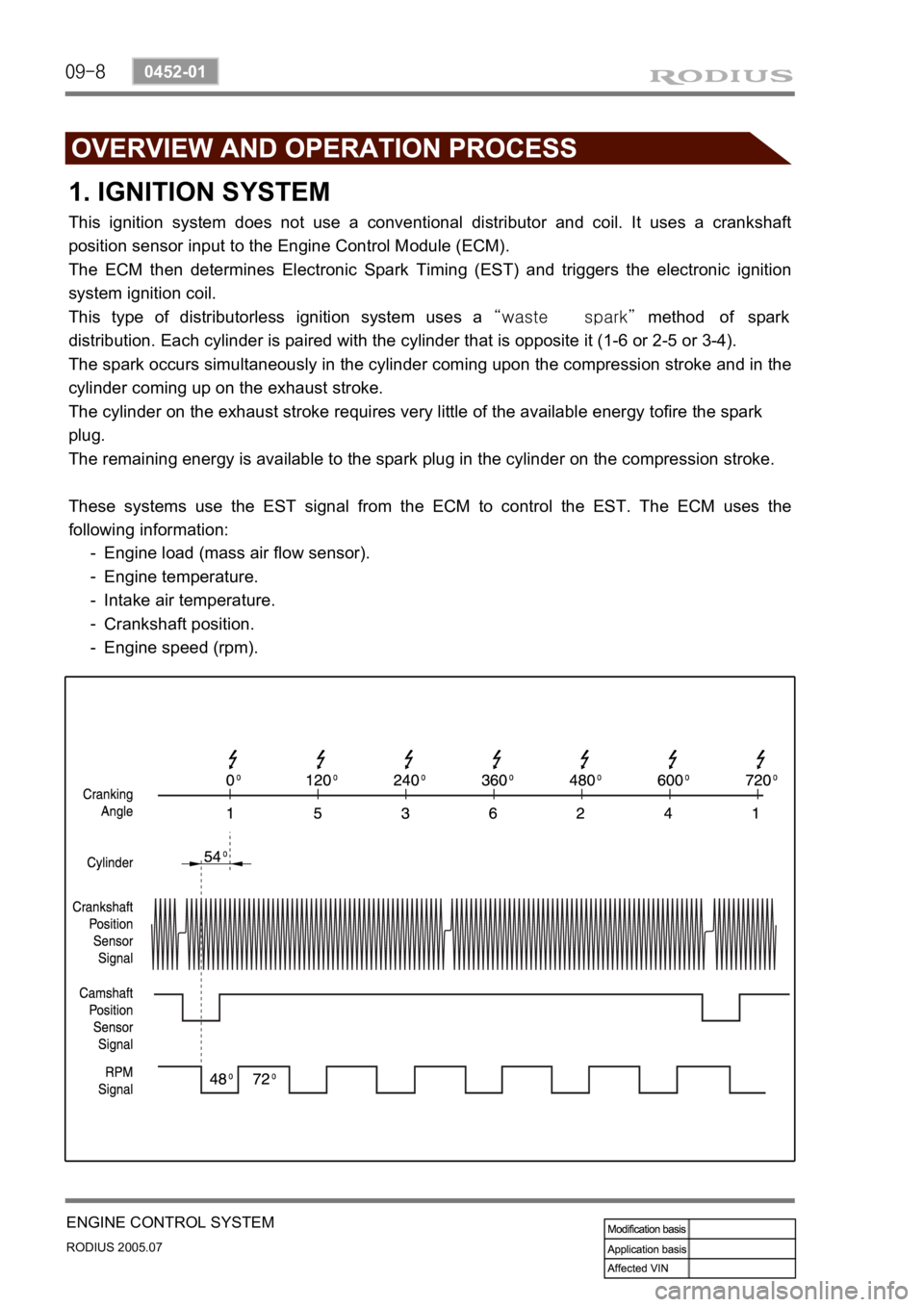
This ignition system does not use a conventional distributor and coil. It uses a crankshaft
position sensor input to the Engine Control Module (ECM).
The ECM then determines Electronic Spark Timing (EST) and triggers the electronic ignition
system ignition coil.
This type of distributorless ignition system uses a “waste spark” method of spark
distribution. Each cylinder is paired with the cylinder that is opposite it (1-6 or 2-5 or 3-4).
The spark occurs simultaneously in the cylinder coming upon the compression stroke and in the
cylinder coming up on the exhaust stroke.
The cylinder on the exhaust stroke requires very little of the available energy tofire the spark
plug.
The remaining energy is available to the spark plug in the cylinder on the compression stroke.
These systems use the EST signal from the ECM to control the EST. The ECM uses the
following information:
Engine load (mass air flow sensor).
Engine temperature.
Intake air temperature.
Crankshaft position.
Engine speed (rpm). -
-
-
-
-
Page 155 of 502
09-9
ENGINE CONTROL SYSTEM
RODIUS 2005.07
0452-01
2. FUEL SYSTEM
The function of the fuel metering system is to deliver the correct amount of fuel to the engine
under all operating conditions.
The fuel is delivered to the engine by the individual fuel injectors mounted into the intake
manifold near each cylinder.
The main fuel control sensors are the Mass Air Flow (MAF) sensor and the oxygen (O2)
sensors.
The MAF sensor monitors the mass flow of the air being drawn into the engine.
An electrically heated element is mounted in the intake air stream, where it is cooled by the
flow of incoming air.
Engine Control Module (ECM) modulates the flow of heating current to maintain the
temperature
differential between the heated film and the intake air at a constant level. The amount o
f
heating current required to maintain the temperature thus provides an index for the mass ai
r
flow.
This concept automatically compensates for variations in air density, as this is one of the
factors that determines the amount of warmth that the surrounding air absorbs from the heated
element. MAF sensor is located between the air filter and the throttle valve.
Under high fuel demands, the MAF sensor reads a high mass flow condition, such as wide
open throttle.
The ECM uses this information to enrich the mixture, thus increasing the fuel injector on?time,
to provide the correct amount of fuel. When decelerating, the mass flow decreases.
This mass flow change is sensed by the MAF sensor and read by the ECM, which then
decreases the fuel injector on?time due to the low fuel demand conditions.
The O2 sensors are located in the exhaust pipe before catalytic converter.
The O2 sensors indicate to the ECM the amount of oxygen in the exhaust gas, and the ECM
changes the air/fuel ratio to the engine by controlling the fuel injectors.
The best air/fuel ratio to minimize exhaust emissions is 14.7 to 1, which allows the catalytic
converter to operate most efficiently. Because of the constant measuring and adjusting of the
air/fuel ratio, the fuel injection system is called a “closed loop” system.
The ECM uses voltage inputs from several sensors to determine how much fuel to provide to
the engine.
The fuel is delivered under one of several conditions, called ‘‘modes”.
Page 156 of 502
09-10
RODIUS 2005.07
0452-01
ENGINE CONTROL SYSTEM
1) Starting Mode
When the ignition is turned ON, the ECM turns the fuel pump relay on for 1 second.
The fuel pump then builds fuel pressure.
The ECM also checks the Engine Coolant Temperature (ECT) sensor and the Throttle Position
(TP) sensor and determines the proper air/fuel ratio for starting the engine.
This ranges from1.5 to 1 at -36°C (-33°F) coolant temperature to 14.7 to 1 at 94°C
(201°F) coolant temperature.
The ECM controls the amount of fuel delivered in the starting mode by changing how long the
fuel injector is turned on and off.
This is done by ‘‘pulsing” the fuel injectors for very short times.
<007b008f008c00470099009c0095004700940096008b008c0047008f0088009a0047009b009e00960047008a00960095008b0090009b009000960095009a0047008a008800930093008c008b004702c402c400960097008c00950047009300960096009702
c9004700880095008b004702c402c4008a00930096009a008c>d loop”.
2) Run Mode
3) Open Loop
When the engine is first started and it is above 690 rpm, the system goes into “open
loop” operation. In “open loop”, the ECM ignores the signal from the O2S and calculates
the air/fuel ratio based on inputs from the ECT sensor and the MAF sensor.
The ECM stays in “open loop” until the following conditions are met:
The O2 has a varying voltage output, showing that it is hot enough to operate properly.
<007b008f008c0047006c006a007b0047009a008c0095009a0096009900470090009a0047008800890096009d008c004700880047009a0097008c008a0090008d0090008c008b0047009b008c00940097008c00990088009b009c0099008c0047004f005900
5900550047005c00b6006a00500055>
A specific amount of time has elapsed after starting the engine. -
-
-
4) Closed Loop
The specific values for the above conditions vary with different engines and are stored in the
Electronically Erasable programmable Read-Only Memory (EEPROM).
When these conditions are met, the system goes into “closed loop” operation. In “closed
loop”, the ECM calculates the air/fuel ratio (fuel injector on-time) based on the signals
from the O2 sensors.
This allows the air/fuel ratio to stay very close to 14.7 to 1.
5) Acceleration Mode
The ECM responds to rapid changes in throttle position and airflow and provides extra fuel.
The ECM responds to changes in throttle position and airflow and reduces the amount of fuel.
When deceleration is very fast, the ECM can cut off fuel completely for short periods of time.
6) Deceleration Mode
Page 157 of 502
09-11
ENGINE CONTROL SYSTEM
RODIUS 2005.07
0452-01
No fuel is delivered by the fuel injectors when the ignition is off.
This prevents dieseling or engine run-on. Also, the fuel is not delivered if there are no reference
pulses received from the CKP sensor.
This prevents flooding.
8) Fuel Cut-Off Mode
Increasing the fuel injector pulse width.
Increasing the idle speed rpm.
Increasing the ignition dwell time. -
-
- When battery voltage is low, the ECM can compensate for a weak spark delivered by the
ignition module by using the following methods
7) Battery Voltage Correction Mode
3. EXHAUST SYSTEM
1) Catalytic Converter
The purpose of the catalytic converter is to convert the three pollutants of carbon
monoxide(CO), hydrocarbons (HC) and oxides of nitrogen (NOx) contained in the exhaust o
f
gasoline engines, into the harmless compounds of water (H2O), carbon dioxide (CO2) and
nitrogen (N2).
The catalytic converter contains a catalyst, a word coming from the Greek and which
designates the element essential for catalyst which triggers chemical reactions without itsel
f
being consumed.
These catalysts in the 3-way catalytic converter are the rare metals platinum (Pt) and rhodium
(Rh).
The catalytic converter consists essentially of three main elements.
The exhaust gases flow through the catalytic converter and, in so doing, coming into contact
with rare metals (Pt and Rh).
The following chemical reaction are produced.
CO + O2 → CO2
HC + O2 → CO2 + H2O
NOx → N2 + O2 -
-
-
Page 158 of 502
09-12
RODIUS 2005.07
0452-01
ENGINE CONTROL SYSTEM
Ignition “OFF” ▶
4. INDUCTION SYSTEM
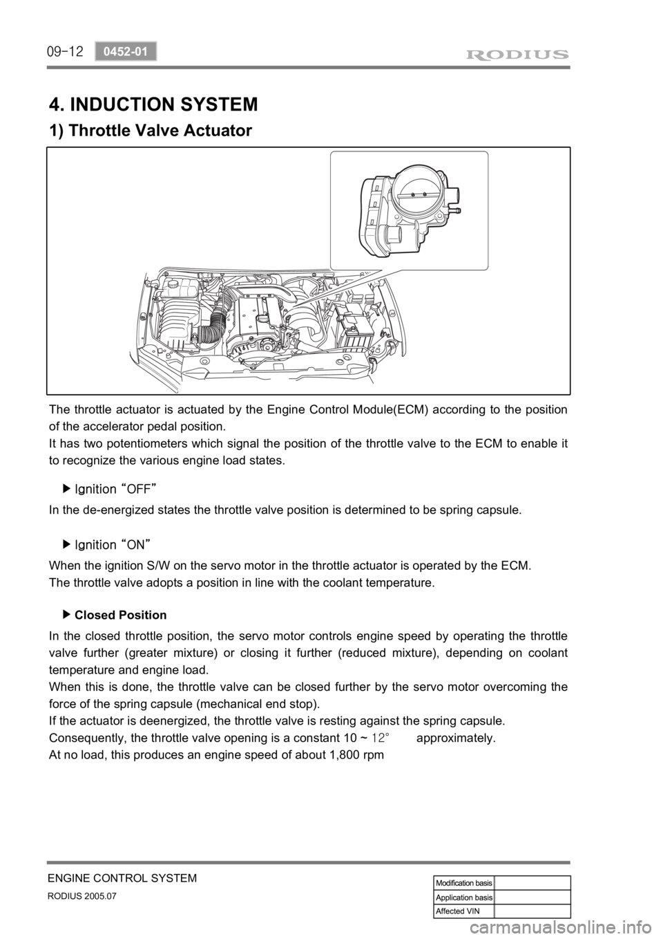
1) Throttle Valve Actuator
The throttle actuator is actuated by the Engine Control Module(ECM) according to the position
of the accelerator pedal position.
It has two potentiometers which signal the position of the throttle valve to the ECM to enable it
to recognize the various engine load states.
In the de-energized states the throttle valve position is determined to be spring capsule.
Ignition “ON” ▶
When the ignition S/W on the servo motor in the throttle actuator is operated by the ECM.
The throttle valve adopts a position in line with the coolant temperature.
In the closed throttle position, the servo motor controls engine speed by operating the throttle
valve further (greater mixture) or closing it further (reduced mixture), depending on coolant
temperature and engine load.
When this is done, the throttle valve can be closed further by the servo motor overcoming the
force of the spring capsule (mechanical end stop).
If the actuator is deenergized, the throttle valve is resting against the spring capsule.
Consequently, the throttle valve opening is a constant 10 ~ 12° approximately.
At no load, this produces an engine speed of about 1,800 rpmClosed Position ▶
Page 159 of 502

09-13
ENGINE CONTROL SYSTEM
RODIUS 2005.07
0452-01
When driving (part/full throttle), the servo motor controls the throttle valve in line with the
various load states and according to the input signals from the pedal value sensor according to
the input signals from the pedal value sensor according to the position of the accelerator pedal.
The function of the EA (electronic accelerator) in the ECM determines the opening angle of the
throttle valve through the throttle actuator.
Further functions areDriving ▶
Idle speed control
Cruise control
Reducing engine torque for ASR/ABS
operation
Electronic accelerator emergency running
Storing faults
Data transfer through CAN -
-
-
-
-
-
-
Page 160 of 502

09-14
RODIUS 2005.07
0452-01
ENGINE CONTROL SYSTEM
1) Diagnosis Circuit
5. SCHEMATIC AND ROUTING
DIAGRAMS