engine SSANGYONG RODIUS 2005 Manual Online
[x] Cancel search | Manufacturer: SSANGYONG, Model Year: 2005, Model line: RODIUS, Model: SSANGYONG RODIUS 2005Pages: 502, PDF Size: 70.43 MB
Page 280 of 502

0-8
RODIUS 2005.07
4610-00
POWER STEERING SYSTEM
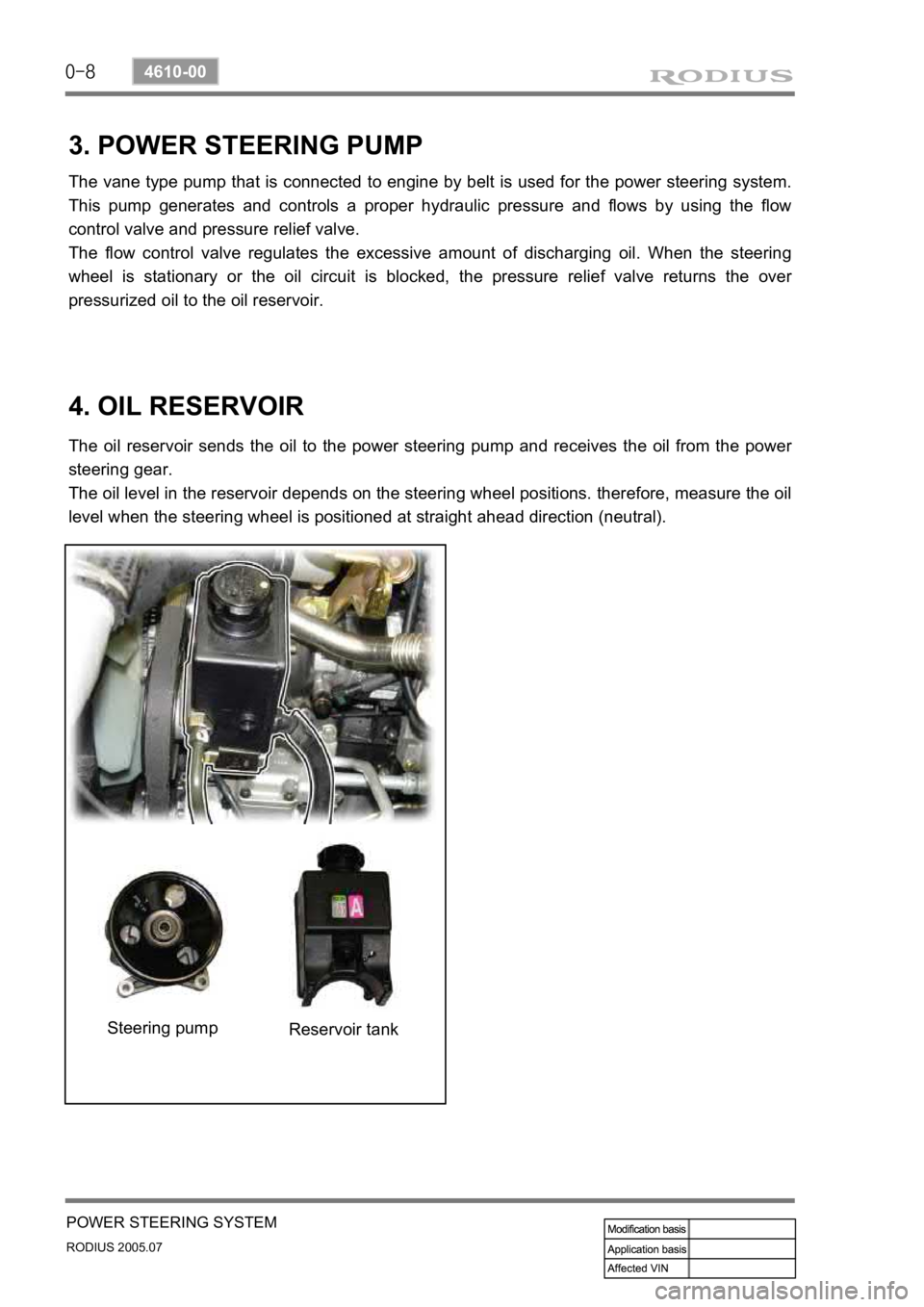
3. POWER STEERING PUMP
The vane type pump that is connected to engine by belt is used for the power steering system.
This pump generates and controls a proper hydraulic pressure and flows by using the flow
control valve and pressure relief valve.
The flow control valve regulates the excessive amount of discharging oil. When the steering
wheel is stationary or the oil circuit is blocked, the pressure relief valve returns the ove
r
pressurized oil to the oil reservoir.
4. OIL RESERVOIR
The oil reservoir sends the oil to the power steering pump and receives the oil from the power
steering gear.
The oil level in the reservoir depends on the steering wheel positions. therefore, measure the oil
level when the steering wheel is positioned at straight ahead direction (neutral).
Steering pump Reservoir tank
Page 286 of 502

0-8
RODIUS 2005.07
4710-09
WHEEL
3. WHEEL ALIGNMENT
The first responsibility of engineering is to design safe steering and suspension systems. Each
component must be strong enough to with stand and absorb extreme punishment.
Both the steering system and the front and the rear suspension must function geometrically
with the body mass.
The steering and suspension systems require that the front wheels self-return and that the tire
rolling effort and the road friction be held to a negligible force in order to allow the customer to
direct the vehicle with the least effort and the most comfort.
A complete wheel alignment check should include measurements of the rear toe and camber.
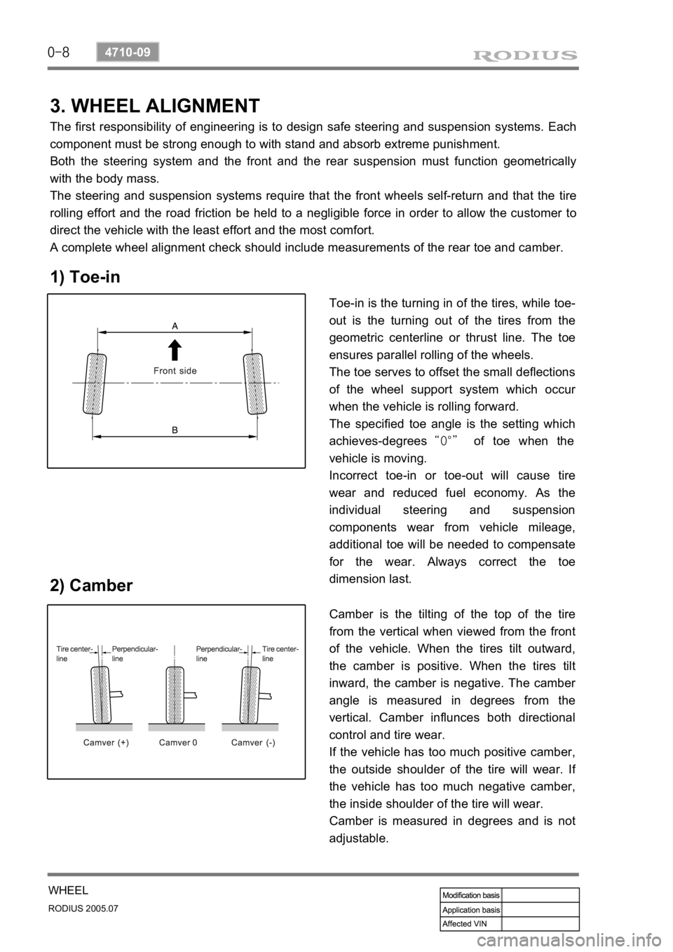
1) Toe-in
2) Camber
Toe-in is the turning in of the tires, while toe-
out is the turning out of the tires from the
geometric centerline or thrust line. The toe
ensures parallel rolling of the wheels.
The toe serves to offset the small deflections
of the wheel support system which occu
r
when the vehicle is rolling forward.
The specified toe angle is the setting which
achieves-degrees “0°” of toe when the
vehicle is moving.
Incorrect toe-in or toe-out will cause tire
wear and reduced fuel economy. As the
individual steering and suspension
components wear from vehicle mileage,
additional toe will be needed to compensate
for the wear. Always correct the toe
dimension last.
Camber is the tilting of the top of the tire
from the vertical when viewed from the front
of the vehicle. When the tires tilt outward,
the camber is positive. When the tires tilt
inward, the camber is negative. The cambe
r
angle is measured in degrees from the
vertical. Camber influnces both directional
control and tire wear.
If the vehicle has too much positive camber,
the outside shoulder of the tire will wear. I
f
the vehicle has too much negative camber,
the inside shoulder of the tire will wear.
Camber is measured in degrees and is not
adjustable.
Page 288 of 502

ELECTRIC GENERAL
0000-00
ELECTRIC GENERAL
GENERAL
1. LOCATIONS OF UNITS AND SENSORS
IN PASSENGER COMPARTMENT.........
2. SWITCHES, UNITS AND SENSORS IN
ENGINE COMPARTMENT (EXCEPT
ENGINE RELATED SENSORS AND
UNITS)...................................................
3. SWITCHES IN PASSENGER
COMPARTMENT...................................
4. SYSTEM LAYOUT (BASED ON DVD
SYSTEM EQUIPPED VEHICLE).............
5. WIRING HARNESS ARRANGEMENT.....
6. COMPONENTS LOCATOR....................
ELECTRIC GENERAL ELECTRIC GENERAL ELECTRIC GENERAL
4
6
8
10
12
13
Page 293 of 502

0-6
RODIUS 2005.07
0000-00
ELECTRIC GENERAL
2. SWITCHES, UNITS AND SENSORS IN ENGINE
COMPARTMENT (EXCEPT ENGINE RELATED
SENSORS AND UNITS)
Page 301 of 502

01-3
FUSE AND RELAY
RODIUS 2005.07
8410-05
8410-05FUSES AND RELAYS
1. ENGINE COMPARTMENT FUSE AND RELAY
BOX
Fuse and relay box is located in the engine compartment, and the interior fuse box is located
under the driver side instrument panel. Especially, ICM box, an integrated circuit of relays, is
mounted along with STICS behind the driver side instrument panel.
Connector arrangement
Back of the fuse and relay box
(after removal)
Fuses and relays
Page 307 of 502

01-9
FUSE AND RELAY
RODIUS 2005.07
8410-05
4. WIRING HARNESS, CONNECTOR & GROUND
LOCATION
1) W/H Engine room
Page 327 of 502

0-14
RODIUS 2005.07
8710-01
STICS
(3) Speed Sensitive INT (Intermittent) Wiper
For STICS without rain sensor, perform the following operation:
1. Controls the wiper intermittent operation by the values from vehicle speed and volume.
Calculates and converts the Intermittent interval automatically by using the vehicle speed
and INT VOLUME when the ignition switch is in “ON” position and the INT switch is in
“ON” position (the engine is running).
The wipers are operated in vehicle speed sensitive mode when turning the INT switch
to “ON” position with the engine running or starting the engine with the INT switch
positioned “ON”.
Intermittent interval (at 0 km/h): 3 ± 0.5 ~ 19 ± 2 seconds -
-
-
2. Vehicle speed calculation
[Input the vehicle speed]
It is calculated by the numbers of input pulses for one second.
1 [pulses/sec] = 60 [km/h] x 60 [sec] / 637 pulses = 1.41 [km/h]
3. VOLUME calculation
Calculates the INT VOLUME with 5 grades as shown in the table in next page. -
4. Pause time calculation
Pause time: the duration that wipers are stopped at parking position
Elapsed time: the duration after the wiper motor started to operate from parking position
The pause time is calculated by the vehicle speed and VOLUME value as shown in the
table in next page. -
-
-
If the pause time is below 1.0 second, the wipers operate without pause.
If the pause time is over 1.5 seconds, the wipers operate intermittently. ·
·
Page 339 of 502

0-26
RODIUS 2005.07
8710-01
STICS
10) Defogger Timer
The system outp<009c009b009a0047009b008f008c0047009b008800900093008e0088009b008c00530047009e00900095008b009a008f0090008c0093008b004700880095008b00470096009c009b009a0090008b008c00470099008c00880099009d0090008c009e004700
94009000990099009600990047008f008c0088009b008c008b> glass “O
signal when turning on the defogger switch (while the engine is running).
The output stops when turning on the defogger switch again during its operation.
The out
p<009c009b00470090009a004702c80076007502c9004700960095009300a00047008d009600990047005d0047009400900095009c009b008c009a0047004f007b005a00500047009e008f008c00950047009b009c0099009500900095008e004702c8007600
7502c90047009b008f008c00470099008c008800990047008b>efogger switch
within 10 minutes (T2) after completion of output.
When turning on the defogger switch again within 10 minutes (T2) after completion of initial
12 minutes (T1) of output, the output comes on for 6 minutes (T3) again once only.
<007b008f008c00470096009c009b0097009c009b0047009a009b00960097009a0047009e008f008c00950047009b008f008c00470070006e0075004700590047009a009e0090009b008a008f00470090009a0047009b009c00990095008c008b0047009b00
96004702c80076006d006d02c9004700970096009a0090009b>ion or the ALT is
“OFF”. 1.
2.
3.
4.
Page 340 of 502

0-27
STICS
RODIUS 2005.07
8710-01
This vehicle has the windshield heated glass and the tailgate and outside rearview mirror
heated glass. The heater relay in the ICM box controls the tailgate and outside rearview mirro
r
heated glass and its fuse (15A) is located in the engine compartment fuse box.
Defogger switch
Page 352 of 502

0-39
STICS
RODIUS 2005.07
8710-01
Armed mode cancellation requirements ▶
Unlocking by remote control key or engine starting. 1.
Warning operation requirements ▶
When opening the door in armed mode
When unlocking the door lock switch in armed mode
When closing and then opening the door after completion of warning (27 seconds) 1.
2.
3.
Warning operation ▶
The theft deterrent horn and hazard warning flasher output is “ON” for T3 (27
seconds) with the interval of T2 (1second). 1.
Warning cancellation requirements ▶
Cancels warning by using any signal from the remote control key (LOCK, UNLOCK,
START, STOP, PANIC, CHECK) during warning operation.
Cancels warning after 27 seconds (remaining period) while the ignition key is turned to
“ON” position. 1.
2.
Operation when warning is cancelled ▶
<007b008f008c0047009b008f008c008d009b0047008b008c009b008c00990099008c0095009b0047008f009600990095004700880095008b0047008f008800a100880099008b0047009e00880099009500900095008e0047008d00930088009a008f008c00
9900470096009c009b0097009c009b009a004700880099008c> “OFF”. 1.