ECO mode SSANGYONG RODIUS 2005 Service Manual
[x] Cancel search | Manufacturer: SSANGYONG, Model Year: 2005, Model line: RODIUS, Model: SSANGYONG RODIUS 2005Pages: 502, PDF Size: 70.43 MB
Page 146 of 502
08-8
RODIUS 2005.07
1452-01
ENGINE ELECTRIC SYSTEM
6) JUMP STARTING PROCEDURE
Position the vehicle with the charged battery so that the jumper cables will reach from the
charged battery to the battery that requires charging.
Turn off the ignition, all the lights, and all the electrical loads in both vehicles.
Leave the hazard flasher on if jump starting where there may be other traffic and any other
lights needed for the work area.
Apply the parking brake firmly in both vehicles. 1.
2.
3.
4.
In order to avoid damaging the vehicle make sure the cables are not on or near pulleys, fans,
or
other parts that will move when the engine starts.
Shift an automatic transmission to PARK. 5.
In order to avoid injury, do not use cables that have loose or missing insulation.
Clamp one end of the first jumper cable to the positive terminal on the booster battery. Make
sure it does not touch any other metal parts.
Clamp the other end of the same cable to the positive terminal on the discharged battery.
Never connect the other end to the negative terminal of the discharged battery. 6.
7.
Do not attach the cable directly to the neg-ative terminal of the discharged battery. Doing so
could cause sparks and possible battery explosion.
Clamp one end of the second cable to the negative terminal of the booster battery.
Make the final connection to a solid engine ground, such as the engine lift bracket at least
450 millimeters (18 inches) from the discharged battery.
Start the engine of the vehicle with the good battery.
Run the engine at a moderate speed for several minutes.
Then start the engine of the vehicle with the discharged battery.
Remove the jumper cables by reversing the above sequence exactly, removing the
negative cable from the vehicle with the discharged battery first. While removing each
clamp, take care that it does not touch any other metal while the other end remains
attached. 8.
9.
10.
11.
12.
7) ALTERNATOR
Alternators are equipped with internal regulators. Unlike three-wire alternators, the alternator
may be used with only two connections: battery positive and an “D+” terminal to the
charge indicator lamp.
As with other charging systems, the charge indicator lamp lights when the ignition switch is
turned to RUN, and goes out when the engine is running. If the charge idicator is on with the
engine running, a charging system defect is indicated. This indicator light will glow at full
brilliance for several kinds of defects as well as when the system voltage is too high or too low.
The regulator voltage setting varies with temperature and limits the system voltage by
controlling rotor field current. Achieve correct average field current for proper system voltage
control by varying the on-off time. At high speeds, the on-time may be 10 percent and the off-
time 90 percent. At low speeds, with high electrical loads, the on-time may be 90 percent and
the off-time 10 percent.
Page 156 of 502
09-10
RODIUS 2005.07
0452-01
ENGINE CONTROL SYSTEM
1) Starting Mode
When the ignition is turned ON, the ECM turns the fuel pump relay on for 1 second.
The fuel pump then builds fuel pressure.
The ECM also checks the Engine Coolant Temperature (ECT) sensor and the Throttle Position
(TP) sensor and determines the proper air/fuel ratio for starting the engine.
This ranges from1.5 to 1 at -36°C (-33°F) coolant temperature to 14.7 to 1 at 94°C
(201°F) coolant temperature.
The ECM controls the amount of fuel delivered in the starting mode by changing how long the
fuel injector is turned on and off.
This is done by ‘‘pulsing” the fuel injectors for very short times.
<007b008f008c00470099009c0095004700940096008b008c0047008f0088009a0047009b009e00960047008a00960095008b0090009b009000960095009a0047008a008800930093008c008b004702c402c400960097008c00950047009300960096009702
c9004700880095008b004702c402c4008a00930096009a008c>d loop”.
2) Run Mode
3) Open Loop
When the engine is first started and it is above 690 rpm, the system goes into “open
loop” operation. In “open loop”, the ECM ignores the signal from the O2S and calculates
the air/fuel ratio based on inputs from the ECT sensor and the MAF sensor.
The ECM stays in “open loop” until the following conditions are met:
The O2 has a varying voltage output, showing that it is hot enough to operate properly.
<007b008f008c0047006c006a007b0047009a008c0095009a0096009900470090009a0047008800890096009d008c004700880047009a0097008c008a0090008d0090008c008b0047009b008c00940097008c00990088009b009c0099008c0047004f005900
5900550047005c00b6006a00500055>
A specific amount of time has elapsed after starting the engine. -
-
-
4) Closed Loop
The specific values for the above conditions vary with different engines and are stored in the
Electronically Erasable programmable Read-Only Memory (EEPROM).
When these conditions are met, the system goes into “closed loop” operation. In “closed
loop”, the ECM calculates the air/fuel ratio (fuel injector on-time) based on the signals
from the O2 sensors.
This allows the air/fuel ratio to stay very close to 14.7 to 1.
5) Acceleration Mode
The ECM responds to rapid changes in throttle position and airflow and provides extra fuel.
The ECM responds to changes in throttle position and airflow and reduces the amount of fuel.
When deceleration is very fast, the ECM can cut off fuel completely for short periods of time.
6) Deceleration Mode
Page 240 of 502
0-7
ESP SYSTEM
RODIUS 2005.07
4892-01
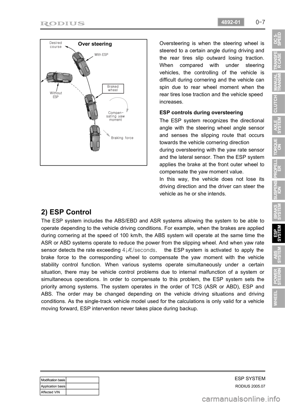
Over steeringOversteering is when the steering wheel is
steered to a certain angle during driving and
the rear tires slip outward losing traction.
When compared with under steering
vehicles, the controlling of the vehicle is
difficult during cornering and the vehicle can
spin due to rear wheel moment when the
rear tires lose traction and the vehicle speed
increases.
ESP controls during oversteering
The ESP system recognizes the directional
angle with the steering wheel angle senso
r
and senses the slipping route that occurs
towards the vehicle cornering direction
during oversteering with the yaw rate senso
r
and the lateral sensor. Then the ESP system
applies the brake at the front outer wheel to
compensate the yaw moment value.
In this way, the vehicle does not lose its
driving direction and the driver can steer the
vehicle as he or she intends.
2) ESP Control
The ESP system includes the ABS/EBD and ASR systems allowing the system to be able to
operate depending to the vehicle driving conditions. For example, when the brakes are applied
during cornering at the speed of 100 km/h, the ABS system will operate at the same time the
ASR or ABD systems operate to reduce the power from the slipping wheel. And when yaw rate
sensor detects the rate exceeding 4¡Æ/seconds, the ESP system is activated to apply the
brake force to the corresponding wheel to compensate the yaw moment with the vehicle
stability control function. When various systems operate simultaneously under a certain
situation, there may be vehicle control problems due to internal malfunction of a system o
r
simultaneous operations. In order to compensate to this problem, the ESP system sets the
priority among systems. The system operates in the order of TCS (ASR or ABD), ESP and
ABS. The order may be changed depending on the vehicle driving situations and driving
conditions. As the single-track vehicle model used for the calculations is only valid for a vehicle
moving forward, ESP intervention never takes place during backup.
Page 241 of 502
0-8
RODIUS 2005.07
4892-01
ESP SYSTEM
2) ESP Control
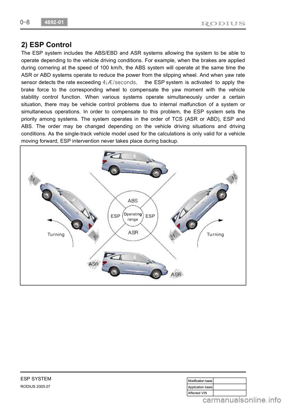
The ESP system includes the ABS/EBD and ASR systems allowing the system to be able to
operate depending to the vehicle driving conditions. For example, when the brakes are applied
during cornering at the speed of 100 km/h, the ABS system will operate at the same time the
ASR or ABD systems operate to reduce the power from the slipping wheel. And when yaw rate
sensor detects the rate exceeding 4¡Æ/seconds, the ESP system is activated to apply the
brake force to the corresponding wheel to compensate the yaw moment with the vehicle
stability control function. When various systems operate simultaneously under a certain
situation, there may be vehicle control problems due to internal malfunction of a system o
r
simultaneous operations. In order to compensate to this problem, the ESP system sets the
priority among systems. The system operates in the order of TCS (ASR or ABD), ESP and
ABS. The order may be changed depending on the vehicle driving situations and driving
conditions. As the single-track vehicle model used for the calculations is only valid for a vehicle
moving forward, ESP intervention never takes place during backup.
Page 270 of 502
0-18
RODIUS 2005.07
4892-01
ABS SYSTEM
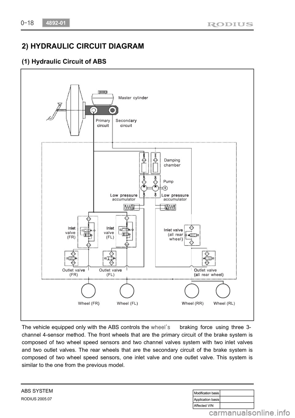
2) HYDRAULIC CIRCUIT DIAGRAM
(1) Hydraulic Circuit of ABS
The vehicle equipped only with the ABS controls the wheel’s braking force using three 3-
channel 4-sensor method. The front wheels that are the primary circuit of the brake system is
composed of two wheel speed sensors and two channel valves system with two inlet valves
and two outlet valves. The rear wheels that are the secondary circuit of the brake system is
composed of two wheel speed sensors, one inlet valve and one outlet valve. This system is
similar to the one from the previous model.
Page 327 of 502
0-14
RODIUS 2005.07
8710-01
STICS
(3) Speed Sensitive INT (Intermittent) Wiper
For STICS without rain sensor, perform the following operation:
1. Controls the wiper intermittent operation by the values from vehicle speed and volume.
Calculates and converts the Intermittent interval automatically by using the vehicle speed
and INT VOLUME when the ignition switch is in “ON” position and the INT switch is in
“ON” position (the engine is running).
The wipers are operated in vehicle speed sensitive mode when turning the INT switch
to “ON” position with the engine running or starting the engine with the INT switch
positioned “ON”.
Intermittent interval (at 0 km/h): 3 ± 0.5 ~ 19 ± 2 seconds -
-
-
2. Vehicle speed calculation
[Input the vehicle speed]
It is calculated by the numbers of input pulses for one second.
1 [pulses/sec] = 60 [km/h] x 60 [sec] / 637 pulses = 1.41 [km/h]
3. VOLUME calculation
Calculates the INT VOLUME with 5 grades as shown in the table in next page. -
4. Pause time calculation
Pause time: the duration that wipers are stopped at parking position
Elapsed time: the duration after the wiper motor started to operate from parking position
The pause time is calculated by the vehicle speed and VOLUME value as shown in the
table in next page. -
-
-
If the pause time is below 1.0 second, the wipers operate without pause.
If the pause time is over 1.5 seconds, the wipers operate intermittently. ·
·
Page 330 of 502
0-17
STICS
RODIUS 2005.07
8710-01
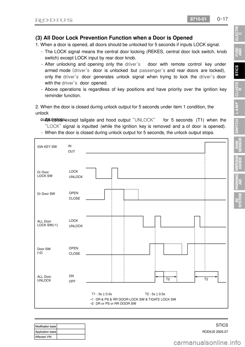
(3) All Door Lock Prevention Function when a Door is Opened
1. When a door is opened, all doors should be unlocked for 5 seconds if inputs LOCK signal.
The LOCK signal means the central door locking (REKES, central door lock switch, knob
switch) except LOCK input by rear door knob.
After unlocking and opening only the driver’s door with remote control key under
armed mode (driver’s door is unlocked but passenger’s and rear doors are locked),
only the driver’s door generates unlock signal when trying to lock the driver’s door
with the driver’s door opened.
Above operations is regardless of key positions and have priority over the ignition key
reminder function. -
-
-
2. When the door is closed during unlock output for 5 seconds under item 1 condition, the
unlock
output stops.
All doors except tailgate and hood output “UNLOCK” for 5 seconds (T1) when the
“LOCK” signal is inputted (while the ignition key is removed and a of door is opened).
When the door is closed during unlock output for 5 seconds, the unlock output stops. -
-
Page 337 of 502
0-24
RODIUS 2005.07
8710-01
STICS
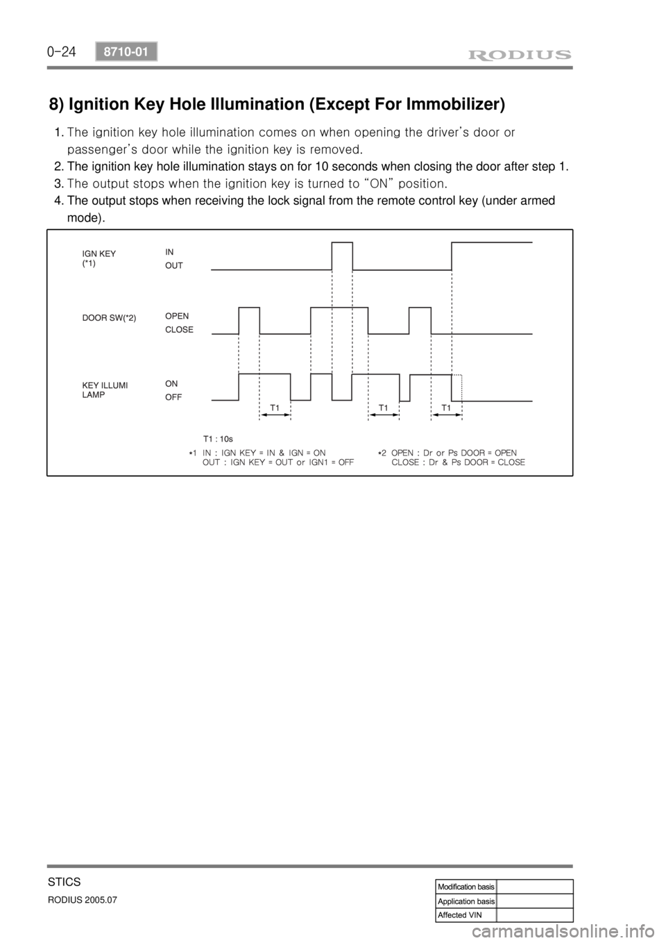
8) Ignition Key Hole Illumination (Except For Immobilizer)
<007b008f008c00470090008e00950090009b00900096009500470092008c00a00047008f00960093008c0047009000930093009c0094009000950088009b0090009600950047008a00960094008c009a0047009600950047009e008f008c00950047009600
97008c009500900095008e0047009b008f008c0047008b0099>iver’s door or
<00970088009a009a008c0095008e008c009902c5009a0047008b0096009600990047009e008f00900093008c0047009b008f008c00470090008e00950090009b00900096009500470092008c00a000470090009a00470099008c00940096009d008c008b00
55>
The ignition key hole illumination stays on for 10 seconds when closing the door after step 1.
<007b008f008c00470096009c009b0097009c009b0047009a009b00960097009a0047009e008f008c00950047009b008f008c00470090008e00950090009b00900096009500470092008c00a000470090009a0047009b009c00990095008c008b0047009b00
96004702c80076007502c9004700970096009a0090009b0090>on.
The output stops when receiving the lock signal from the remote control key (under armed
mode). 1.
2.
3.
4.
Page 342 of 502
0-29
STICS
RODIUS 2005.07
8710-01
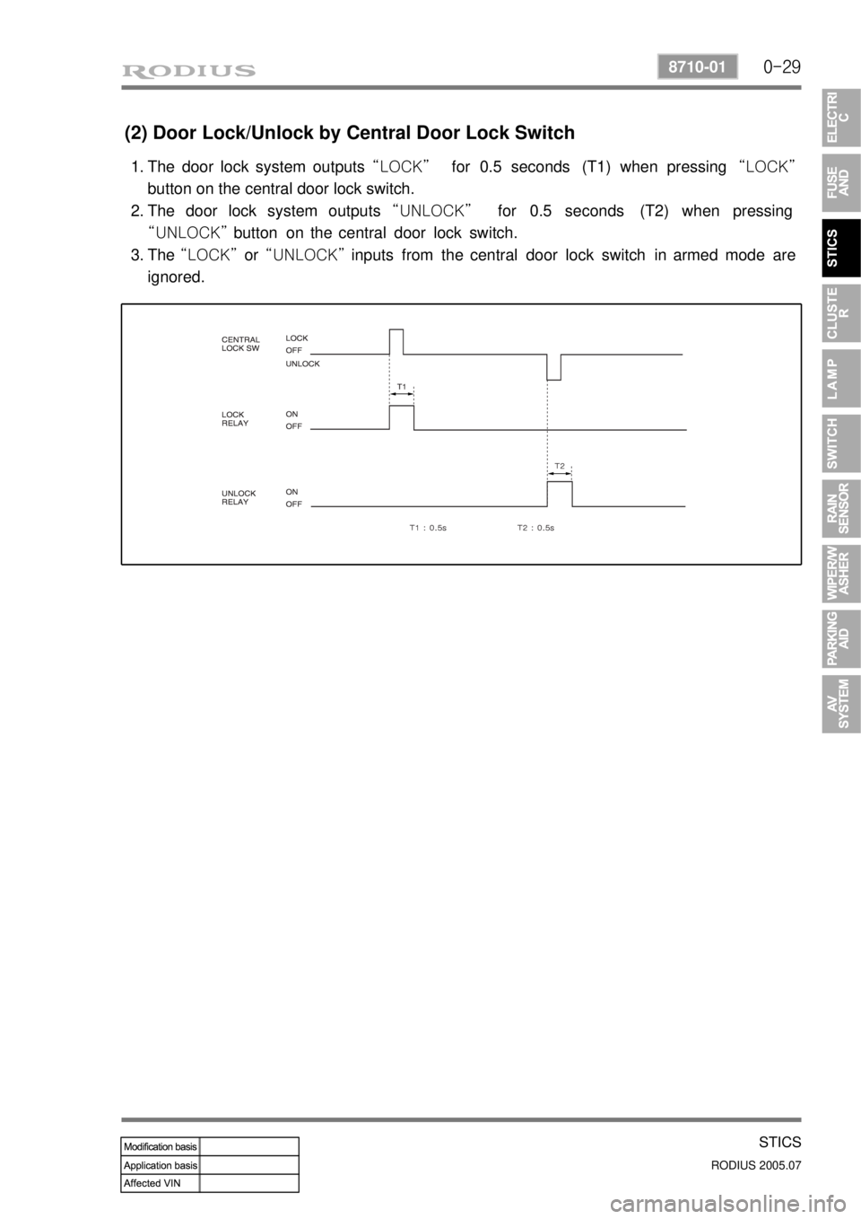
(2) Door Lock/Unlock by Central Door Lock Switch
The door lock system outputs “LOCK” for 0.5 seconds (T1) when pressing “LOCK”
button on the central door lock switch.
The door lock system outputs “UNLOCK” for 0.5 seconds (T2) when pressing
“UNLOCK” button on the central door lock switch.
The “LOCK” or “UNLOCK” inputs from the central door lock switch in armed mode are
ignored. 1.
2.
3.
Page 347 of 502
0-34
RODIUS 2005.07
8710-01
STICS
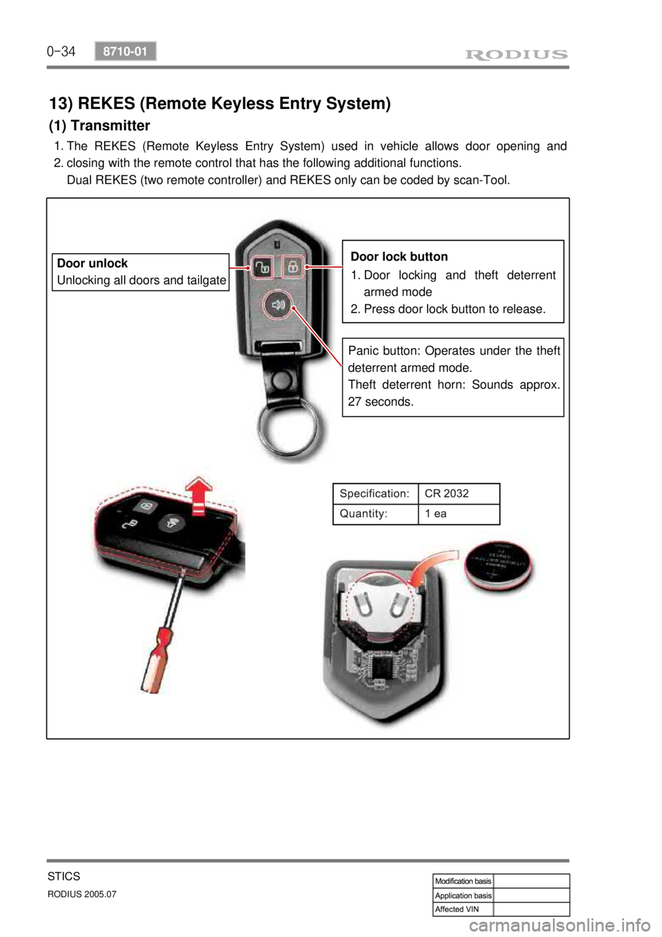
13) REKES (Remote Keyless Entry System)
(1) Transmitter
The REKES (Remote Keyless Entry System) used in vehicle allows door opening and
closing with the remote control that has the following additional functions.
Dual REKES (two remote controller) and REKES only can be coded by scan-Tool.
1.
2.
Door locking and theft deterrent
armed mode
Press door lock button to release.
1.
2.
Door lock button
Panic button: Operates under the theft
deterrent armed mode.
Theft deterrent horn: Sounds approx.
27 seconds.
Door unlock
Unlocking all doors and tailgate