SSANGYONG RODIUS 2005 Service Manual
RODIUS 2005
SSANGYONG
SSANGYONG
https://www.carmanualsonline.info/img/67/57522/w960_57522-0.png
SSANGYONG RODIUS 2005 Service Manual
Page 4 of 502
0-4RODIUS 2005.07
0000-00
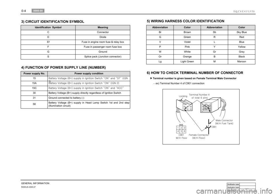
GENERAL INFORMATION3) CIRCUIT IDENTIFICATION SYMBOL
Identification Symbol Meaning
C Connector
D Diode
Ef Fuse in engine room fuse & relay box
F Fuse in passenger room fuse box
G Ground
S Splice pack (Junction connector)
5) WIRING HARNESS COLOR IDENTIFICATION
Abbreviation Color Abbreviation Color
Br Brown Sb Sky Blue
G Green R Red
V Violet L Blue
P Pink Y Yellow
W White Gr Gray
Or Orange B Black
Lg Light Green M Maroon
6) HOW TO CHECK TERMINAL NUMBER OF CONNECTOR
Terminal number is given based on Female Terminal Male Connector ▶
ex) Terminal Number 4 of C901 connection -
Power supply No. Power supply condition
15<00690088009b009b008c009900a00047007d00960093009b0088008e008c0047004f0069005200500047009a009c00970097009300a000470090009500470070008e00950090009b0090009600950047007a009e0090009b008a008f004702c80076007502
c9004700880095008b004702c8007a007b02c90047004f0070>GN
1)
15A<00690088009b009b008c009900a00047007d00960093009b0088008e008c0047004f0069005200500047009a009c00970097009300a000470090009500470070008e00950090009b0090009600950047007a009e0090009b008a008f004702c80076007502
c90047004f0070006e0075004700590050>
15C<00690088009b009b008c009900a00047007d00960093009b0088008e008c0047004f0069005200500047009a009c00970097009300a000470090009500470070008e00950090009b0090009600950047007a009e0090009b008a008f004702c80076007502
c9004700880095008b004702c80068006a006a02c9>
30 Battery Voltage (B+) supply directly regardless of Ignition Switch
31 Ground connected to battery (-)
58Battery Voltage (B+) supply in Head Lamp Switch 1st and 2nd step
(Illumination circuit)4) FUNCTION OF POWER SUPPLY LINE (NUMBER)
Page 5 of 502
0-5
GENERAL INFORMATION
RODIUS 2005.07
0000-00
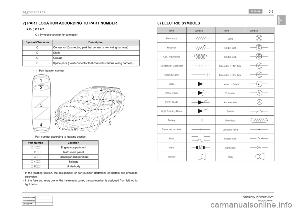
7) PART LOCATION ACCORDING TO PART NUMBER
Ex.) C 1 0 2 ▶
C : Symbol character for connector -
Symbol Character Description
C Connector (Connecting part that connects two wiring harness)
D Diode
G Ground
S Splice pack (Joint connector that connects various wiring harness)
1 : Part location number -
Part number according to locating section -
Part Numbe Location
□ 1□□Engine compartment
□ 2□□Instrument panel
□ 3□□Passenger compartment
□ 4□□Tailgate
□ 9□□Underbody
In the locating section, the assignment for part number startsfrom left bottom and proceeds
clockwise.
In the fuse and relay box or the instrument panel, the partnumber is assigned from left top to
light bottom. -
-
8) ELECTRIC SYMBOLS
Page 33 of 502
POWER DISTRIBUTION
8410-02/8410-05POWER DISTRIBUTION
FUSE/RELAY8410-02 ENGINE ROOM FUSE &
RELAY BOX.................................
8410-05 I.P FUSE & ICM BOX
(IP RELAY BOX)...........................ELECTRICITY DIVIDE8210-02 ENG ROOM FUSE BOX...............
8410-04 I.P FUSE BOX..............................3
5
7
11
Page 35 of 502
0-3
POWER DISTRIBUTION
RODIUS 2005.07
8410-02
FUSE & RELAY8410-02
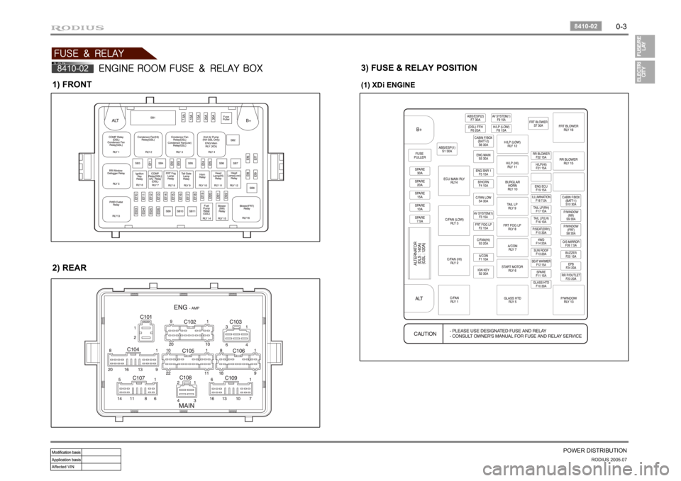
ENGINE ROOM FUSE & RELAY BOX
1) FRONT2) REAR
3) FUSE & RELAY POSITION(1) XDi ENGINE
Page 36 of 502
0-4RODIUS 2005.07
8410-02
POWER DISTRIBUTION
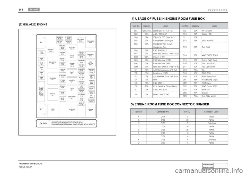
4) USAGE OF FUSE IN ENGINE ROOM FUSE BOX
5) ENGINE ROOM FUSE BOX CONNECTOR NUMBER
(2) GSL (G23) ENGINE
Page 37 of 502
0-5
POWER DISTRIBUTION
RODIUS 2005.07
8410-05
8410-05
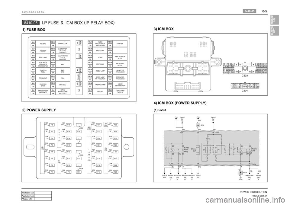
I.P FUSE & ICM BOX (IP RELAY BOX)
1) FUSE BOX2) POWER SUPPLY
3) ICM BOX4) ICM BOX (POWER SUPPLY)(1) C203
Page 39 of 502
0-7
POWER DISTRIBUTION
RODIUS 2005.07
8410-02
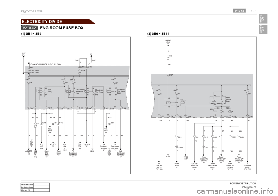
ELECTRICITY DIVIDE8210-02
ENG ROOM FUSE BOX
(1) SB1 ~ SB5
(2) SB6 ~ SB11
Page 43 of 502
0-11
POWER DISTRIBUTION
RODIUS 2005.07
8410-04
8410-04
I.P FUSE BOX
(1) F1 ~ F5
(2) F6 ~ F12
Page 265 of 502
0-13
ABS SYSTEM
RODIUS 2005.07
4892-01
1) System Fuse
2) Indicators
The ABS/TCS system fuse and SB2 is
located at the fuse box in engine
compartment.
The ABS and TCS indicators are in
instrument cluster.
Page 301 of 502
01-3
FUSE AND RELAY
RODIUS 2005.07
8410-05
8410-05FUSES AND RELAYS
1. ENGINE COMPARTMENT FUSE AND RELAY
BOX
Fuse and relay box is located in the engine compartment, and the interior fuse box is located
under the driver side instrument panel. Especially, ICM box, an integrated circuit of relays, is
mounted along with STICS behind the driver side instrument panel.
Connector arrangement
Back of the fuse and relay box
(after removal)
Fuses and relays

