service SSANGYONG RODIUS 2005 Service Manual
[x] Cancel search | Manufacturer: SSANGYONG, Model Year: 2005, Model line: RODIUS, Model: SSANGYONG RODIUS 2005Pages: 502, PDF Size: 70.43 MB
Page 112 of 502
01-5
ENGINE GENERAL
RODIUS 2005.07
0000-00
2. DESCRIPTION AND OPERATION
1) CLEANLINESS AND CARE
An automobile engine is a combination of many machined, honed, polished and lapped
surfaces with tolerances that are measured in the ten-thousanths of an inch. When any internal
engine parts are serviced, care and cleanliness are important. A liberal coating of enigne oil
should be applied to friction areas during assembly, to protect and lubricate the surfaces on
initial operation. Proper cleaning and protection of machined surfaces and friction areas is part
of the repair procedure. This is considered standard shop practice even if not specifically
stated.
Whenever valve train components are removed for service, they should be kept in order. They
should be installed in the same locations, and with the same mating surfaces, as when they
were removed.
Battery cables should be disconnected before any major work is performed on the engine.
Failure to disconnect cables may result in damage to wire harness or other electrical parts.
2) ON-ENGINE SERVICE
Disconnect the negative battery cable before removing or installing any electrical unit, or
when a tool or equipment could easily come in contact with exposed electrical terminals.
Disconnecting this cable will help prevent personal injury and damage to the vehicle.
The ignition must also be in LOCK unless otherwise noted. -
Any time the air cleaner is removed, the intake opening should be covered. This will
protect against accidental entrance of foreign material, which could follow the intake
passage into the cylinder and cause extensive damage when the engine is started. -
Page 117 of 502
02-6
RODIUS 2005.07
1113-01
ENGINE ASSEMBLY
3. DESCRIPTION AND OPERATION
1) CLEANLINESS AND CARE
An automobile engine is a combination of many machined, honed, polished and lapped
surfaces with tolerances that are measured in the ten-thousanths of an inch. When any internal
engine parts are serviced, care and cleanliness are important. A liberal coating of enigne oil
should be applied to friction areas during assembly, to protect and lubricate the surfaces on
initial operation. Proper cleaning and protection of machined surfaces and friction areas is part
of the repair procedure. This is considered standard shop practice even if not specifically
stated.
Whenever valve train components are removed for service, they should be kept in order. They
should be installed in the same locations, and with the same mating surfaces, as when they
were removed.
Battery cables should be disconnected before any major work is performed on the engine.
Failure to disconnect cables may result in damage to wire harness or other electrical parts.
2) ON-ENGINE SERVICE
Disconnect the negative battery cable before removing or installing any electrical unit, or
when a tool or equipment could easily come in contact with exposed electrical terminals.
Disconnecting this cable will help prevent personal injury and damage to the vehicle.
The ignition must also be in LOCK unless otherwise noted. -
Any time the air cleaner is removed, the intake opening should be covered. This will protect
against accidental entrance of foreign material, which could follow the intake passage into
the cylinder and cause extensive damage when the engine is started. -
Page 124 of 502
07-8
RODIUS 2005.07
2110-01
ENGINE COOLING SYSTEM
5) WATER PUMP
The belt-driven centrifugal water pump consists of an impeller, a drive shaft, and a belt pulley.
The impeller is supported by a completely sealed bearing.
The water pump is serviced as an assembly and, therefore, cannot be disassembled.
6) ELECTRIC COOLING FAN
Keep hands, tools, and clothing away from the engine cooling fans to help prevent
personal injury. This fan is electric and can turn on even when the engine is not running. -
f a fan blade is bent or damaged in any way, no attempt should be made to repair or reuse
the damaged part.
A bent or damaged fan assembly should always be replaced with a new one to prevent
possible injury. -
The cooling fans are mounted behind the radiator in the engine compartment. The electric
cooling fans increase the flow of air across the radiator fins and across the condenser on ai
r
conditioned (A/C)-equipped vehicles.
This helps to speed cooling when the vehicle is at idle or moving at low speeds.
All models have two fans. The main fan is 320 mm (12.6 inches) in diameter with seven blades
to aid the airflow through the radiator and the condenser. An electric motor attached to the
radiator support drives the fan. The auxiliary fan is 320 mm (12.6 inches) in diameter.
7) A/C OFF OR NON-AC MODEL
The cooling fans are actuated by the engine control module (ECM) using a low-speed
cooling fan relay, a high-speed cooling fan relay and a cooling fan motor relay.
The ECM will turn the cooling fans on at low speed when the coolant temperature reaches
95°C (203°F) and at high speed when the coolant temperature reaches 105°C (221°F).
The ECM will change the cooling fans from high peed to low speed at 100°C (212°F)
and will turn the cooling fans off at 90°C (194°F). ·
·
·
Page 143 of 502

08-5
ENGINE ELECTRIC SYSTEM
RODIUS 2005.07
1452-01
1. DESCRIPTION AND OPERATION OF ENGINE
ELECTRICAL SYSTEM
1) BATTERY
The sealed battery is standard on all cars. There are no vent plugs in the cover. The battery is
completely sealed, except for two small vent holes in the sides.
These vent holes allow the small amount of gas pro-duced in the battery to escape. The battery
has the following advantages over conventional batteries:
No water addition for the life of the battery.
Overcharge protection. If too much voltage is applied to the battery, it will not accept as
much current as a conventional battery. In a conventional battery, the excess voltage will
still try to charge the battery, leading to gassing, which causes liquid loss.
Not as liable to self-discharge as a conventional battery. This is particularly important when
a battery is left standing for long periods of time.
More power available in a lighter, smaller case. -
-
-
-
The battery has three major functions in the electrical system. First, the battery provides a
source of energy for cranking the engine. Second, the battery acts as a voltage stabilizer for the
electrical system. Finally, the battery can, for a limited time, provide energy when the electrical
demand exceeds the output of the alternator.
2) RATINGS
A battery has two ratings: (1) a reserve capacity rating designated at 27°C (80°F), which
is the time a fully charged battery will provide 25 amperes of current flow at or above 10.5 volts;
(2) a cold cranking amp rating determined under testing at -18°C (0°F), which indicates
the cranking
load capacity.
▶Reserve Capacity
The reserve capacity (RC) is the maximum length of time it is possible to travel at night with the
minimum electrical load and no alternator output. Expressed in minutes, the RC rating is the
time required for a fully charged battery, at a temperature of 27 °C (80 °F) and being
discharged at
a current of 25 amperes, to reach a terminal voltage of 10.5 volts.
▶Cold Cranking Amperage
The cold cranking amperage test is expressed at a battery temperature of -18°C (0°F).
The current rating is the minimum amperage, which must be maintained by the battery for 30
seconds at the specified temperature, while meeting a minimum voltage requirement of 7.2
volts. This
rating is a measure of cold cranking capacity.
The battery is not designed to last indefinitely. However, with proper care, the battery will
provide many years of service. If the battery tests well, but fails to perform satisfactorily
in service for no apparent reason, the following factors may point to the cause of the trouble:
Page 147 of 502
08-9
ENGINE ELECTRIC SYSTEM
RODIUS 2005.07
1452-01
8) STARTER
Wound field starter motors have pole pieces, arranged around the armature, which are
energized by wound field coils.
Enclosed shift lever cranking motors have the shift lever mechanism and the solenoid plunge
r
enclosed in the drive housing, protecting them from exposure to dirt, icy conditions, and
splashes. In the basic circuit, solenoid windings are energized when the switch is closed. The
resulting plunger and shift lever movement causes the pinion to engage the engine flywheel
ring gear. The solenoid main contacts close. Cranking then takes place.
When the engine starts, pinion overrun protects the armature from excessive speed until the
switch is opened, at which time the return spring causes the pinion to disengage.
To prevent excessive overrun, the switch should be released immediately after the engine
starts.
9) STARTING SYSTEM
The engine electrical system includes the battery, the ignition, the starter, the alternator, and all
the related wiring.
Diagnostic tables will aid in troubleshooting system faults.
When a fault is traced to a particular component, refer to that component section of the service
manual.
The starting system circuit consists of the battery, the starter motor, the ignition switch, and all
the related electrical wiring. All of these components are connected electrically.
Page 262 of 502
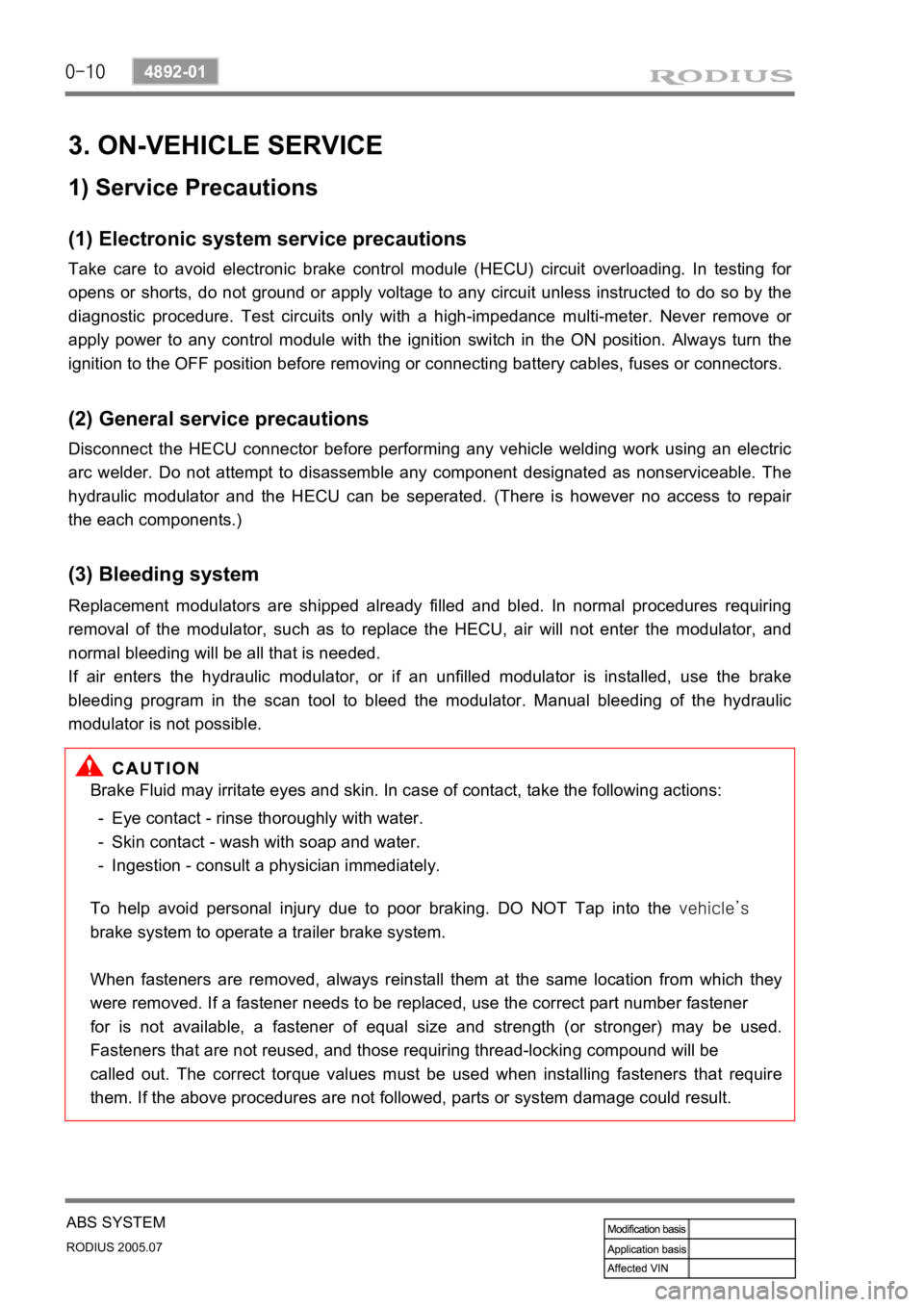
0-10
RODIUS 2005.07
4892-01
ABS SYSTEM
3. ON-VEHICLE SERVICE
(1) Electronic system service precautions
Take care to avoid electronic brake control module (HECU) circuit overloading. In testing for
opens or shorts, do not ground or apply voltage to any circuit unless instructed to do so by the
diagnostic procedure. Test circuits only with a high-impedance multi-meter. Never remove o
r
apply power to any control module with the ignition switch in the ON position. Always turn the
ignition to the OFF position before removing or connecting battery cables, fuses or connectors.
(2) General service precautions
Disconnect the HECU connector before performing any vehicle welding work using an electric
arc welder. Do not attempt to disassemble any component designated as nonserviceable. The
hydraulic modulator and the HECU can be seperated. (There is however no access to repai
r
the each components.)
(3) Bleeding system
Replacement modulators are shipped already filled and bled. In normal procedures requiring
removal of the modulator, such as to replace the HECU, air will not enter the modulator, and
normal bleeding will be all that is needed.
If air enters the hydraulic modulator, or if an unfilled modulator is installed, use the brake
bleeding program in the scan tool to bleed the modulator. Manual bleeding of the hydraulic
modulator is not possible.
1) Service Precautions
Brake Fluid may irritate eyes and skin. In case of contact, take the following actions:
Eye contact - rinse thoroughly with water.
Skin contact - wash with soap and water.
Ingestion - consult a physician immediately. -
-
-
To help avoid personal injury due to poor braking. DO NOT Tap into the vehicle’s
brake system to operate a trailer brake system.
When fasteners are removed, always reinstall them at the same location from which they
were removed. If a fastener needs to be replaced, use the correct part number fastener
for is not available, a fastener of equal size and strength (or stronger) may be used.
Fasteners that are not reused, and those requiring thread-locking compound will be
called out. The correct torque values must be used when installing fasteners that require
them. If the above procedures are not followed, parts or system damage could result.
Page 268 of 502

0-16
RODIUS 2005.07
4892-01
ABS SYSTEM
Service precautions ▶
Observe the following general precautions during any ABS/TCS service. Failure to adhere to
these precautions may result in ABS/TCS system damage.
Disconnect the EBCM harness connector before performing the electric welding procedures.
Carefully note the routing of the ABS/TCS wiring and wiring components during removal.
The ABS/ TCS components are extremely sensitive to EMI (eletromagnetic interference).
Proper mounting is critical during component service.
Disconnect the EBCM connector with the ignition OFF.
Do not hang the suspension components from the wheel speed sensor cables. The cables
may be damaged.
Do not use petroleum based fluids in the master cylinder. Do not use any containers
previously used for petroleum based fluids. Petroleum causes swelling and distortion of the
rubber components in the hydraulic brake system, resulting in water entering the system
and lowering the fluid boiling point. 1.
2.
3.
4.
5.
Page 362 of 502

0-10
RODIUS 2005.07
8010-10
CLUSTER
3) Fuel Level Gauge
The fuel level gauge displays the resistance value of the float on the fuel sender in the fuel tank
through a pointer. Note that this vehicle doesn’t have a service hole for checking the fuel
sender connector in the fuel tank.
The fuel sender and its connector can be checked and replaced only when the fuel tank is
removed. The power supply and resistance value should be measured at the connector in front
of the fuel sender (refer to wiring diagram).
When the power supply and output resistance are normal, the float operation by fuel level may
be defective; if so, replace the fuel sender.
Tolerance and resistance value by indicating angle
This table shows the tolerance and resistance value changes by fuel level in normal conditions.
Therefore, the differences that can be occurred by the road conditions and fuel fluctuations are
ignored.
Page 444 of 502

0-7
AIR BAG SYSTEM
RODIUS 2005.07
8810-01
4) Inflator
The inflator is a type of the direct gas generated device.
The inflator with initial low pressure provides negative restraint effect regarding passengers
moving and time.
On the contrary, the inflator with initial high pressure allows other components of the airbag
to make a excessive impact resulting in any personal injury.
Thus, the inflator output must be optimized according to the characteristic of the vehicle and
passenger moving.
The discharge gas has no toxicity or inflammability and also it is the important parameter to
control the high temperature for gas firing. ·
·
·
5) SDM (Sensing and Diagnostic Module)
The airbag system consists of the module section (driver, passenger and side), seat belt
section and SDM.
The SDM has no user-serviceable parts and monitors the system components continuously.
The SDM also records any faults which are discovered.
The SDM allows the fault codes to be retrieved with a scan tool and illuminates a warning
lamp that alerts the driver to any faults. 1.
2.
3.
The SDM located on floor beneath the floor console assembly. The SDM performs the
following functions:
Impact decision processor function.
Determine the airbag deployment through the impact signal of the accelerometer sensor and
the safety sensor. ·
·
Malfunction detection and recording any faults that are detected.
Monitor the supplemental restrain system electrical components and set a diagnostic trouble
code when malfunction is detected.
Display airbag fault codes Display airbag fault codes and system status information when
connected to a scan tool.
Self-diagnosis function Illuminate the AIRBAG indicator to alert the driver to any fault.
Power supply function Provide a reserve power source to deploy the airbags and
pretensioners if an accident has disabled the normal power source. ·
·
·
·
Page 447 of 502

0-10
RODIUS 2005.07
8810-01
AIR BAG SYSTEM
11) Wiring Harness Connectors
If the sensing and diagnostic module (SDM) electrical connector is not attached properly, a built
in shorting bar will connect the wire from airbag warning lamp with the SDM ground wire. This
turns on the AIRBAG indicator.
To prevent deployment during servicing, additional shorting bars are located in following
locations:
Driver airbag module connector
Passenger airbag module connector
Driver and passenger side airbag module connector
SDM wiring harness connector
Contact coil connector to airbag wiring harness ·
·
·
·
·
The shorting bar is only a backup safety device. Always disable the supplemental restraints
system (SRS) before beginning any service procedure.
12) Belt Pretensioner
The belt pretensioner enables to retract the driver and the passenger seat belt webbing to
reduce any personal impact when accounted a frontal collision.