ENGINE CONTROL SSANGYONG RODIUS 2006 User Guide
[x] Cancel search | Manufacturer: SSANGYONG, Model Year: 2006, Model line: RODIUS, Model: SSANGYONG RODIUS 2006Pages: 444, PDF Size: 56.32 MB
Page 155 of 444

0-10
RODIUS 2007.07
0000-00
CDEF(Catalytic Disel Particulate Filter)
4) Throttle Body for Different Engines
The throttle body is not installed in the D27DT engine (general), but is installed in the following
engines:
1) D27DT (EU IV) engine
2) D27DTP (POWER UP) engine
3) D27DTP (POWER UP) engine + CDPF
Both engines are equipeed with the throttle body, but its appearance and the related control
system are differ.
Page 157 of 444
0-12
RODIUS 2007.07
0000-00
CDEF(Catalytic Disel Particulate Filter)
6) CDPF Over Load (Notice of Beginning CPF Regeneration Mode
- P1430)
The CDPF system enters the regeneration mode when the mileage is around 600 ~ 1,200
km, depending on the driving condition and driving habits. At this moment, the ECU
performs the CDPF regeneration process; however, the driver may not notice anything
because there is no engine warning or other signals indicating such process.
The control logic in the regeneration process is to increase the exhaust gas temperature by
increasing the fuel injection during post injection process and controlling the intake ai
r
amount(throttle body), and no significant change can be noticed in the vehicle condition.
The engine CHECK lamp flashes but there is no decrease in engine torque.
The engine CHECK lamp flashes to inform the driver when there is an over load due to soot
accumulation because the regeneration temperature cannot be reached due to low speed,
even though CDPF regeneration is in process.
The CDPF regeneration process must be completed by driving for 15-20 minutes at a speed
higher than 80 km/h to solve this problem.
The engine CHECK lamp flashes when CDPF is over loaded; therefore, 4) above must be
performed in this case. 1.
2.
3.
4.
5.
7) CDPF's Excessive Soot Accumulation (P0432)
When the vehicle is driven at a low speed (5-10 km/h) for a long time or long distance, the
soot over accumulates inside the CDPF and the combustion temperature cannot be reached
even by performing the soot combustion process. In this case, this DTC is generated.
This is more serious situation than the CDPF over load condition. Therefore, the engine
power is decreased to protect the system and the engine CHECK lamp is turned on.
Blow the soot between the engine and the exhaust system several times and clear the DTC
to solve this problem. If the same DTC is generated again, check the system according to
the DTC description related to the differential pressure sensor.
* This DTC is actually generated mostly due to the related system malfunction, such as
differential pressure sensor malfunction. 1.
2.
3.
Page 187 of 444
0-14
RODIUS 2007.07
8710-01
STICS
(3) Speed Sensitive INT (Intermittent) Wiper
For STICS without rain sensor, perform the following operation:
1. Controls the wiper intermittent operation by the values from vehicle speed and volume.
Calculates and converts the Intermittent interval automatically by using the vehicle speed
and INT VOLUME when the ignition switch is in “ON” position and the INT switch is in
“ON” position (the engine is running).
The wipers are operated in vehicle speed sensitive mode when turning the INT switch
to “ON” position with the engine running or starting the engine with the INT switch
positioned “ON”.
Intermittent interval (at 0 km/h): 3 ± 0.5 ~ 19 ± 2 seconds -
-
-
2. Vehicle speed calculation
[Input the vehicle speed]
It is calculated by the numbers of input pulses for one second.
1 [pulses/sec] = 60 [km/h] x 60 [sec] / 637 pulses = 1.41 [km/h]
3. VOLUME calculation
Calculates the INT VOLUME with 5 grades as shown in the table in next page. -
4. Pause time calculation
Pause time: the duration that wipers are stopped at parking position
Elapsed time: the duration after the wiper motor started to operate from parking position
The pause time is calculated by the vehicle speed and VOLUME value as shown in the
table in next page. -
-
-
If the pause time is below 1.0 second, the wipers operate without pause.
If the pause time is over 1.5 seconds, the wipers operate intermittently. ·
·
Page 200 of 444
0-27
STICS
RODIUS 2007.07
8710-01
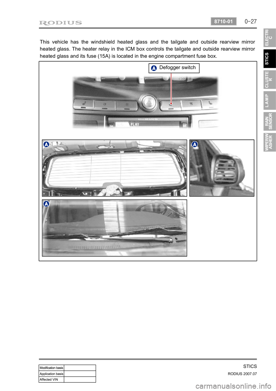
This vehicle has the windshield heated glass and the tailgate and outside rearview mirror
heated glass. The heater relay in the ICM box controls the tailgate and outside rearview mirro
r
heated glass and its fuse (15A) is located in the engine compartment fuse box.
Defogger switch
Page 212 of 444
0-39
STICS
RODIUS 2007.07
8710-01
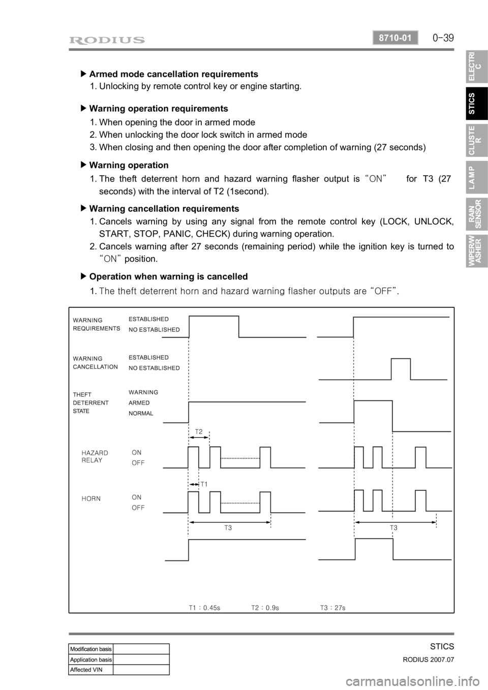
Armed mode cancellation requirements ▶
Unlocking by remote control key or engine starting. 1.
Warning operation requirements ▶
When opening the door in armed mode
When unlocking the door lock switch in armed mode
When closing and then opening the door after completion of warning (27 seconds) 1.
2.
3.
Warning operation ▶
The theft deterrent horn and hazard warning flasher output is “ON” for T3 (27
seconds) with the interval of T2 (1second). 1.
Warning cancellation requirements ▶
Cancels warning by using any signal from the remote control key (LOCK, UNLOCK,
START, STOP, PANIC, CHECK) during warning operation.
Cancels warning after 27 seconds (remaining period) while the ignition key is turned to
“ON” position. 1.
2.
Operation when warning is cancelled ▶
<007b008f008c0047009b008f008c008d009b0047008b008c009b008c00990099008c0095009b0047008f009600990095004700880095008b0047008f008800a100880099008b0047009e00880099009500900095008e0047008d00930088009a008f008c00
9900470096009c009b0097009c009b009a004700880099008c> “OFF”. 1.
Page 213 of 444

0-40
RODIUS 2007.07
8710-01
STICS
15) PANIC Warning
The PANIC warning output is “ON” (theft deterrent horn) when receiving the PANIC
signal from the remote control key (pressing PANIC button for less than 0.5 ~ 1.0 second).
The PANIC warning output is “OFF” when receiving any signal from the remote control
key during PANIC warning.
Followings are theft deterrent warnings: 1.
2.
3.
This function operates only in armed mode.
The system sends the current vehicle conditions (LOCK, engine running) when the PANIC
warning is turned off by the remote control key. 4.
5.The theft deterrent warning is canceled when receiving PANIC signal from the remote
control key during theft deterrent.
The theft deterrent warning output is “ON” when the theft deterrent conditions are
established during PANIC warning (PANIC output is “OFF”).
The PANIC warning output is “ON” when receiving the PANIC signal from the remote
control key in Armed Ready / Armed / Warning Completion / Relock Ready mode
(maintaining the theft deterrent mode). 1)
2)
3)
Page 216 of 444
0-4
RODIUS 2007.07
8010-10
CLUSTER
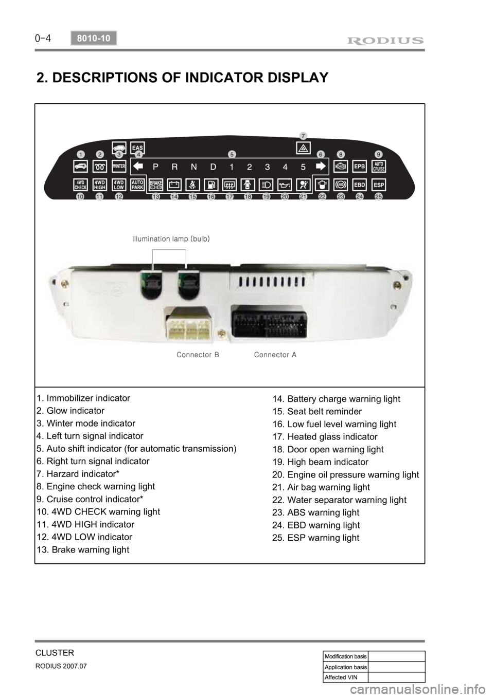
2. DESCRIPTIONS OF INDICATOR DISPLAY
1. Immobilizer indicator
2. Glow indicator
3. Winter mode indicator
4. Left turn signal indicator
5. Auto shift indicator (for automatic transmission)
6. Right turn signal indicator
7. Harzard indicator*
8. Engine check warning light
9. Cruise control indicator*
10. 4WD CHECK warning light
11. 4WD HIGH indicator
12. 4WD LOW indicator
13. Brake warning light14. Battery charge warning light
15. Seat belt reminder
16. Low fuel level warning light
17. Heated glass indicator
18. Door open warning light
19. High beam indicator
20. Engine oil pressure warning light
21. Air bag warning light
22. Water separator warning light
23. ABS warning light
24. EBD warning light
25. ESP warning light
Page 235 of 444

0-12
RODIUS 2007.07
8310-01
LAMP
▶When Using a Screen Install a screen (2m X 1.5m) in front of the headlamps in vertical by 3m away and align the
center lines of the vehicle and the screen.
1.
Run the engine with approx. 2,000 rpm
and turn on the headlamp. At this
moment, the focus of the headlamp
should aim the “A” point.
2.
If the focus deviates the “A” point,
adjust the headlamp aiming by rotating
control levers (Up, Down, Left, Right) in
turn with a screwdriver.
3.(Unit: mm) (Unit: mm)
Page 271 of 444

0-4
RODIUS 2007.07
3010-01
CLUTCH
1. OVERVIEW
1) Driving Elements
The driving elements consist of two flat surfaces machined to a smooth finish.
One of these is the rear face of the engine flywheel and the other is the clutch cover pressure
plate. The clutch pressure plate is fitted into a clutch steel cover, which is bolted to the flywheel.
2) Driven Elements
The driven element is the clutch disc with a splined hub which is free to slide lengthwise along
the splines of the input shaft. The driving and driven elements are held in contact by spring
pressure. This pressure is exerted by a diaphragm spring in the clutch cover pressure plate
assembly.
3) Operating Elements
The clutch control system consists of the clutch pedal, clutch master cylinder, concentric slave
cylinder. This system directly releases the clutch by using hydraulic pressure while the
conventional clutch system releases the clutch by using release lever and release fork. This
system provides higher efficiency than conventional clutch system, and its durability is superior.
Adaptor (mounted on transmission case) Concentric slave cylinder pipe (mounted inside o
f
transmission) Concentric slave cylinder (mounted inside of transmission)
Page 278 of 444
0-5
TORQUE ON DEMAND
RODIUS 2007.07
3240-01
2. GENERAL DESCRIPTION
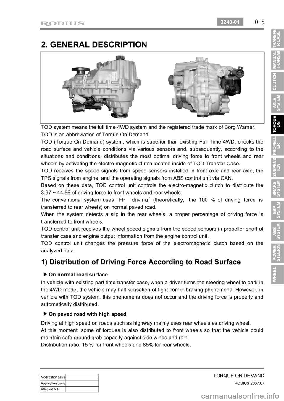
TOD system means the full time 4WD system and the registered trade mark of Borg Warner.
TOD is an abbreviation of Torque On Demand.
TOD (Torque On Demand) system, which is superior than existing Full Time 4WD, checks the
road surface and vehicle conditions via various sensors and, subsequently, according to the
situations and conditions, distributes the most optimal driving force to front wheels and rea
r
wheels by activating the electro-magnetic clutch located inside of TOD Transfer Case.
TOD receives the speed signals from speed sensors installed in front axle and rear axle, the
TPS signals from engine, and the operating signals from ABS control unit via CAN.
Based on these data, TOD control unit controls the electro-magnetic clutch to distribute the
3:97 ~ 44:56 of driving force to front wheels and rear wheels.
The conventional system uses “FR driving” (theoretically, the 100 % of driving force is
transferred to rear wheels) on normal paved road.
When the system detects a slip in the rear wheels, a proper percentage of driving force is
transferred to front wheels.
TOD control unit receives the wheel speed signals from the speed sensors in propeller shaft o
f
transfer case and engine output information from the engine control unit.
TOD control unit changes the pressure force of the electromagnetic clutch based on the
analyzed data.
1) Distribution of Driving Force According to Road Surface
On normal road surface ▶
In vehicle with existing part time transfer case, when a driver turns the steering wheel to park in
the 4WD mode, the vehicle may halt sensation of tight corner braking phenomena. However, in
vehicle with TOD system, this phenomena does not occur and the driving force is properly and
automatically distributed.
On paved road with high speed ▶
Driving at high speed on roads such as highway mainly uses rear wheels as driving wheel.
At this moment, some of torques is also distributed to front wheels so that the vehicle could
maintain safe ground grab capacity against side winds and rain.
Distribution ratio: 15 % for front wheels and 85% for rear wheels.