ENGINE CONTROL SSANGYONG RODIUS 2006 Owner's Manual
[x] Cancel search | Manufacturer: SSANGYONG, Model Year: 2006, Model line: RODIUS, Model: SSANGYONG RODIUS 2006Pages: 444, PDF Size: 56.32 MB
Page 305 of 444

0-6
RODIUS 2007.07
4892-01
ESP SYSTEM
3. ESP SYSTEM DESCRIPTION
1) Principle of ESP
ESP (Electronic Stability Program) recognizes critical driving conditions, such as panic
reactions in dangerous situations, and stabilizes the vehicle by wheel-individual braking and
engine control intervention with no need for actuating the brake. This system is developed to
help the driver avoid the danger of losing the control of the vehicle stability due to under-
steering or over-steering during cornering.
The yaw rate sensor, lateral sensor and longitudinal sensor in the sensor cluster and the
steering wheel angle sensor under the steering column detect the spin present at any wheels
during over-steering, under-steering or cornering. The ESP ECU controls against over-steering
or under-steering during cornering by controlling the vehicle stability using the input values from
the sensors and applying the brakes independently to the corresponding wheels.
The system also controls during cornering by detecting the moment right before the spin and
automatically limiting the engine output (coupled with the ASR system).
Understeering is when the steering wheel is
steered to a certain angle during driving and
the front tires slip toward the reverse
direction of the desired direction. Generally,
vehicles are designed to have unde
r
steering. The vehicle can return back to
inside of cornering line when the steering
wheel is steered toward the inside even
when the vehicle front is slipped outward.
As
the centrifugal force increases, the tires can
easily lose the traction and the vehicle tends
to slip outward when the curve angle gets
bigger and the speed increases. Under steering
ESP controls during under steering
The ESP system recognizes the directional
angle with the steering wheel angle senso
r
and senses the slipping route that occurs
reversely against the vehicle cornering
direction during understeering with the yaw
rate sensor and the lateral sensor. Then the
ESP system applies the brake at the rea
r
inner wheel to compensate the yaw moment
value.
In this way, the vehicle does not lose its
driving direction and the driver can steer the
vehicle as driver intends.
Page 313 of 444

0-14
RODIUS 2007.07
4892-01
ESP SYSTEM
(1) System Overview
When equipped with ABS, the braking force at each wheel will be controlled with 3-channel 4-
sensor method. And when equipped with ESP, 4 wheels will be controlled independently with 4-
channel method. (When controlling ABS system only, it will be operated with 3-channel
method.) When compared to the vehicle equipped with ABS/EBD only, the internal hydraulic
circuit has a normally-open separation valve and a shuttle valve in primary circuit and in
secondary circuit. When the vehicle brakes are not applied during engine running or when
applying the non-ABS operating brakes, the normally-open separation valve and the inlet valve
are open, whereas the normally-closed shuttle valve and the outlet valve are closed. When the
ESP system is operating, the normally-open separation valve will be closed by the solenoid
valve operation and the hydraulic circuit will be established by the shuttle valve. Then, the inlet
and outlet valves will be
closed or open depending on the braking pressure increase, decrease or unchanged
conditions.
<0d96007b008f008c0047009e00880099009500900095008e004700930088009400970047008a00960094008c009a004700960095004700880095008b0047009e00880099009500900095008e00470089008c008c00970047009a0096009c0095008b009a00
47009e008f008c00950047009b008f008c0047006c007a0077> is operating
▶Driving feeling when the ESP is operating
<0d96007500960090009a008c004700880095008b0047009d0090008900990088009b0090009600950047009b008f0088009b0047008b00990090009d008c00990047009a008c0095009a008c009a0047009e008f008c00950047009b008f008c0047006c00
7a007700470090009a004700960097008c00990088009b0090>ng When the ESP operates during vehicle movement, the ESP warning lamp on the instrument
panel flickers and beep comes on every 0.1 seconds. The ESP operation shows that the
vehicle stability is extremely unstable and it is used to warn the driver. The ESP system is just a
supplementary system for the vehicle motion and it cannot control the vehicle when it exceeds
the physical limits. Do not solely rely on the system but be advised to drive the vehicle safely.
When the ESP system activates, the driving feeling can be different depending on vehicle
driving conditions. For example, you will feel differently when the ESP system is activated
during when ABS is operating with the brakes applied and when brakes are not applied on a
curve. Thus, the ESP system would make the driver feel more abruptly when the brakes are
applied during the ESP system activation.
The ESP system may transfer noise and vibration to the driver due to the pressure changes
caused by the motor and valve operations in a very short period of time. Extreme cornering will
trigger the ESP operation and this will make the driver feel noise and vibration due to sudden
brake application. Also, the ESP system controls the engine output. So, the driver may notice
the engine output decrease even when the accelerator pedal is being applied.
Page 346 of 444

0-8
RODIUS 2007.07
4610-00
POWER STEERING SYSTEM
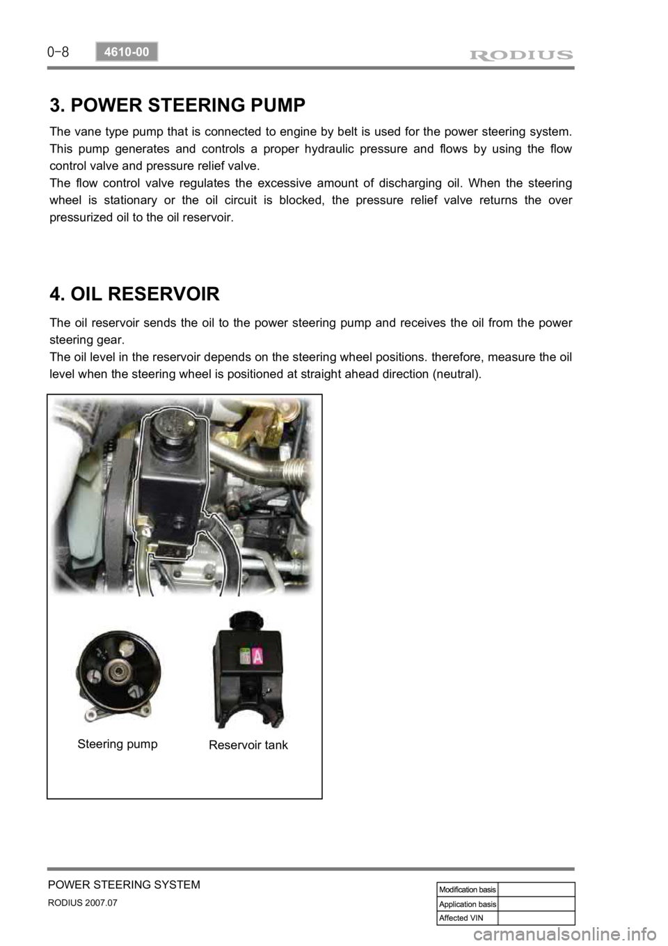
3. POWER STEERING PUMP
The vane type pump that is connected to engine by belt is used for the power steering system.
This pump generates and controls a proper hydraulic pressure and flows by using the flow
control valve and pressure relief valve.
The flow control valve regulates the excessive amount of discharging oil. When the steering
wheel is stationary or the oil circuit is blocked, the pressure relief valve returns the ove
r
pressurized oil to the oil reservoir.
4. OIL RESERVOIR
The oil reservoir sends the oil to the power steering pump and receives the oil from the power
steering gear.
The oil level in the reservoir depends on the steering wheel positions. therefore, measure the oil
level when the steering wheel is positioned at straight ahead direction (neutral).
Steering pump Reservoir tank
Page 352 of 444

0-8
RODIUS 2007.07
4710-09
WHEEL
3. WHEEL ALIGNMENT
The first responsibility of engineering is to design safe steering and suspension systems. Each
component must be strong enough to with stand and absorb extreme punishment.
Both the steering system and the front and the rear suspension must function geometrically
with the body mass.
The steering and suspension systems require that the front wheels self-return and that the tire
rolling effort and the road friction be held to a negligible force in order to allow the customer to
direct the vehicle with the least effort and the most comfort.
A complete wheel alignment check should include measurements of the rear toe and camber.
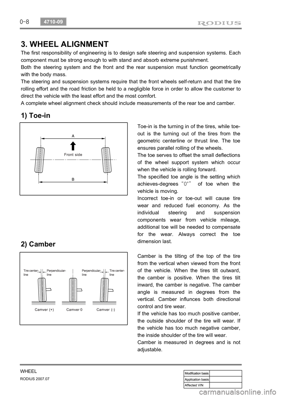
1) Toe-in
2) Camber
Toe-in is the turning in of the tires, while toe-
out is the turning out of the tires from the
geometric centerline or thrust line. The toe
ensures parallel rolling of the wheels.
The toe serves to offset the small deflections
of the wheel support system which occu
r
when the vehicle is rolling forward.
The specified toe angle is the setting which
achieves-degrees “0°” of toe when the
vehicle is moving.
Incorrect toe-in or toe-out will cause tire
wear and reduced fuel economy. As the
individual steering and suspension
components wear from vehicle mileage,
additional toe will be needed to compensate
for the wear. Always correct the toe
dimension last.
Camber is the tilting of the top of the tire
from the vertical when viewed from the front
of the vehicle. When the tires tilt outward,
the camber is positive. When the tires tilt
inward, the camber is negative. The cambe
r
angle is measured in degrees from the
vertical. Camber influnces both directional
control and tire wear.
If the vehicle has too much positive camber,
the outside shoulder of the tire will wear. I
f
the vehicle has too much negative camber,
the inside shoulder of the tire will wear.
Camber is measured in degrees and is not
adjustable.
Page 374 of 444

0-23
AIR CONDITIONING SYSTEM
RODIUS 2007.07
6810-20
3) Mode Door Actuator
The mode door actuator is an actuator that closes, opens and adjusts the mode door for VENT,
FLOOR and DEF mode to change the air flow directions according to FATC controller. Unde
r
the FATC controller AUTO mode, it stays on DEF mode until the engine coolant temperature
reaches at normal operating level and the mode is changed as below when the MODE switch is
pressed.