ENGINE CONTROL SSANGYONG RODIUS 2006 Service Manual
[x] Cancel search | Manufacturer: SSANGYONG, Model Year: 2006, Model line: RODIUS, Model: SSANGYONG RODIUS 2006Pages: 444, PDF Size: 56.32 MB
Page 25 of 444

CIRCUIT
1491-01/8210-01/3670-01/4891-01/4920-01/4480-01/8810-01/8010-01/7630-02/8710-03/8510-03/4810-10/8510-00/8510-26/8910-01/6810-21/6910-01/6810-30
CIRCUIT
ENGINE
CHASSIS3670-01 TCU (5-SPEED)............................
4891-01 ABS/ESP......................................
4920-01 EPB..............................................
4480-01 EAS..............................................ELECTRIC
8910-01 AUDIO (MULTI VISION)................
8910-01 AUDIO..........................................
6810-21 PTC HEATER (POSITIVE
TEMPERATURE
COEFFICIENT).............................
6910-01 FFH (FUEL FIRED HEATER).........
6810-30 FATC (FULL AUTO TEMP.
CONTROL) CIRCUIT....................
6810-30 AIR-CON (MANUAL).....................
8810-01 AIR-BAG.......................................
8010-01 CLUSTER.....................................
7630-02 CIGAR LIGHTER, POWER
OUTLET......................................
8710-03 STICS..........................................
8510-03 POWER WINDOW CIRCUIT..........
4810-10 STOP & BACK-UP LAMP
CIRCUIT.......................................
8510-00 HEAD LAMP LEVELING DEVICE
CIRCUIT.......................................
8510-26 TURN SIGNAL & HAZARD LAMP
CIRCUIT.......................................7
9
11
12
13
14
17
18
22
23
24
2526
29
30
31
32
35 1491-01 ECU (ENGINE CONTROL UNIT -
D27DT EU IV)...............................
8210-01 DIAGNOSIS CIRCUIT...................3
6
Page 27 of 444

0-3
CIRCUITundefined
1491-01
1491-01
ECU (ENGINE CONTROL UNIT - D27DT EU IV)
1) ENG MAIN RELAY, PEDAL MODULE, HFM SENSOR, VALVE
(1) CONNECTOR INFORMATION
(2) CONNECTOR IDENTIFICATION SYMBOL & PIN NUMBER POSITION
Page 78 of 444

05-3
ENGINE EXHAUST SYSTEM
RODIUS 2007.07
0000-00
2420-01ENGINE EXHAUST SYSTEM
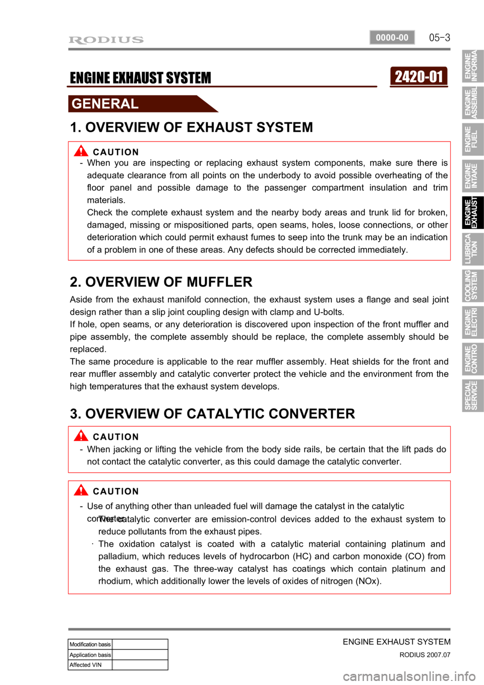
1. OVERVIEW OF EXHAUST SYSTEM
When you are inspecting or replacing exhaust system components, make sure there is
adequate clearance from all points on the underbody to avoid possible overheating of the
floor panel and possible damage to the passenger compartment insulation and trim
materials.
Check the complete exhaust system and the nearby body areas and trunk lid for broken,
damaged, missing or mispositioned parts, open seams, holes, loose connections, or othe
r
deterioration which could permit exhaust fumes to seep into the trunk may be an indication
of a problem in one of these areas. Any defects should be corrected immediately. -
2. OVERVIEW OF MUFFLER
Aside from the exhaust manifold connection, the exhaust system uses a flange and seal joint
design rather than a slip joint coupling design with clamp and U-bolts.
If hole, open seams, or any deterioration is discovered upon inspection of the front muffler and
pipe assembly, the complete assembly should be replace, the complete assembly should be
replaced.
The same procedure is applicable to the rear muffler assembly. Heat shields for the front and
rear muffler assembly and catalytic converter protect the vehicle and the environment from the
high temperatures that the exhaust system develops.
3. OVERVIEW OF CATALYTIC CONVERTER
When jacking or lifting the vehicle from the body side rails, be certain that the lift pads do
not contact the catalytic converter, as this could damage the catalytic converter. -
Use of anything other than unleaded fuel will damage the catalyst in the catalytic
converter. -
The catalytic converter are emission-control devices added to the exhaust system to
reduce pollutants from the exhaust pipes.
The oxidation catalyst is coated with a catalytic material containing platinum and
palladium, which reduces levels of hydrocarbon (HC) and carbon monoxide (CO) from
the exhaust gas. The three-way catalyst has coatings which contain platinum and
rhodium, which additionally lower the levels of oxides of nitrogen (NOx). ·
·
Page 91 of 444

08-6
RODIUS 2007.07
0000-00
ENGINE ELECTRIC DEVICES
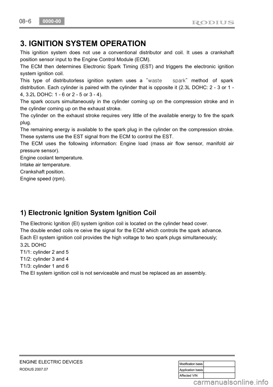
3. IGNITION SYSTEM OPERATION
This ignition system does not use a conventional distributor and coil. It uses a crankshaft
position sensor input to the Engine Control Module (ECM).
The ECM then determines Electronic Spark Timing (EST) and triggers the electronic ignition
system ignition coil.
This type of distributorless ignition system uses a “waste spark” method of spark
distribution. Each cylinder is paired with the cylinder that is opposite it (2.3L DOHC: 2 - 3 or 1 -
4, 3.2L DOHC: 1 - 6 or 2 - 5 or 3 - 4).
The spark occurs simultaneously in the cylinder coming up on the compression stroke and in
the cylinder coming up on the exhaust stroke.
The cylinder on the exhaust stroke requires very little of the available energy to fire the spark
plug.
The remaining energy is available to the spark plug in the cylinder on the compression stroke.
These systems use the EST signal from the ECM to control the EST.
The ECM uses the following information: Engine load (mass air flow sensor, manifold ai
r
pressure sensor).
Engine coolant temperature.
Intake air temperature.
Crankshaft position.
Engine speed (rpm).
1) Electronic Ignition System Ignition Coil
The Electronic Ignition (EI) system ignition coil is located on the cylinder head cover.
The double ended coils re ceive the signal for the ECM which controls the spark advance.
Each EI system ignition coil provides the high voltage to two spark plugs simultaneously;
3.2L DOHC
T1/1: cylinder 2 and 5
T1/2: cylinder 3 and 4
T1/3: cylinder 1 and 6
The EI system ignition coil is not serviceable and must be replaced as an assembly.
Page 93 of 444

09-3
ENGINE CONTROL SYSTEM
RODIUS 2007.07
0000-00
1522-16ENGINE CONTROL SYSTEM
1. ENGINE DATA DISPLAY TABLE
Page 94 of 444

09-4
RODIUS 2007.07
0000-00
ENGINE CONTROL SYSTEM
2. FASTENER TIGHTENING SPECIFICATIONS
1) TEMPERATURE VS RESISTANCE
Page 143 of 444

0-5
ENGINE FUEL SYSTEM
RODIUS 2007.07
0000-00
3) Fuel Rail - Chrome Color
D27DTP & D27DT (EU IV) * Fuel pipe (Common rail → Injector)
* Fuel high pressure pipe (HP pump →
Common rail)
D27DT * Fuel pipe (Common rail → Injector)
* Fuel high pressure pipe (HP pump →
Common rail) The I.D and O.D of the fuel rail between
HP pump and common rail are increased
according to the increased amount of fuel
injection.
Also, the engine ECU, HFM sensor and
EGR system are changed to control the
fuel injection volume and engine more
precisely.
·
Page 146 of 444

0-3
ENGINE INTAKE SYSTEM
RODIUS 2007.07
0000-00
2321-01ENGINE INTAKE SYSTEM
1. INTAKE SYSTEM LAYOUT
The intake system for the D27DTP (POWER UP) engine is equipped with the throttle body that
has a flap to block the air coming to the engine when the engine is switched off. Therefore, the
structure of the intake manifold has been changed.
Also, the improved HFM sensor (from HFM5.0 to HFM6.0) has been installed to control the
intake air precisely so that the NOx in the exhaust gas can be decreased.
Page 147 of 444

0-3
ENGINE EXHAUST SYSTEM
RODIUS 2007.07
1792-01
1792-01ENGINE EXHAUST SYSTEM
1. COMPONENTS
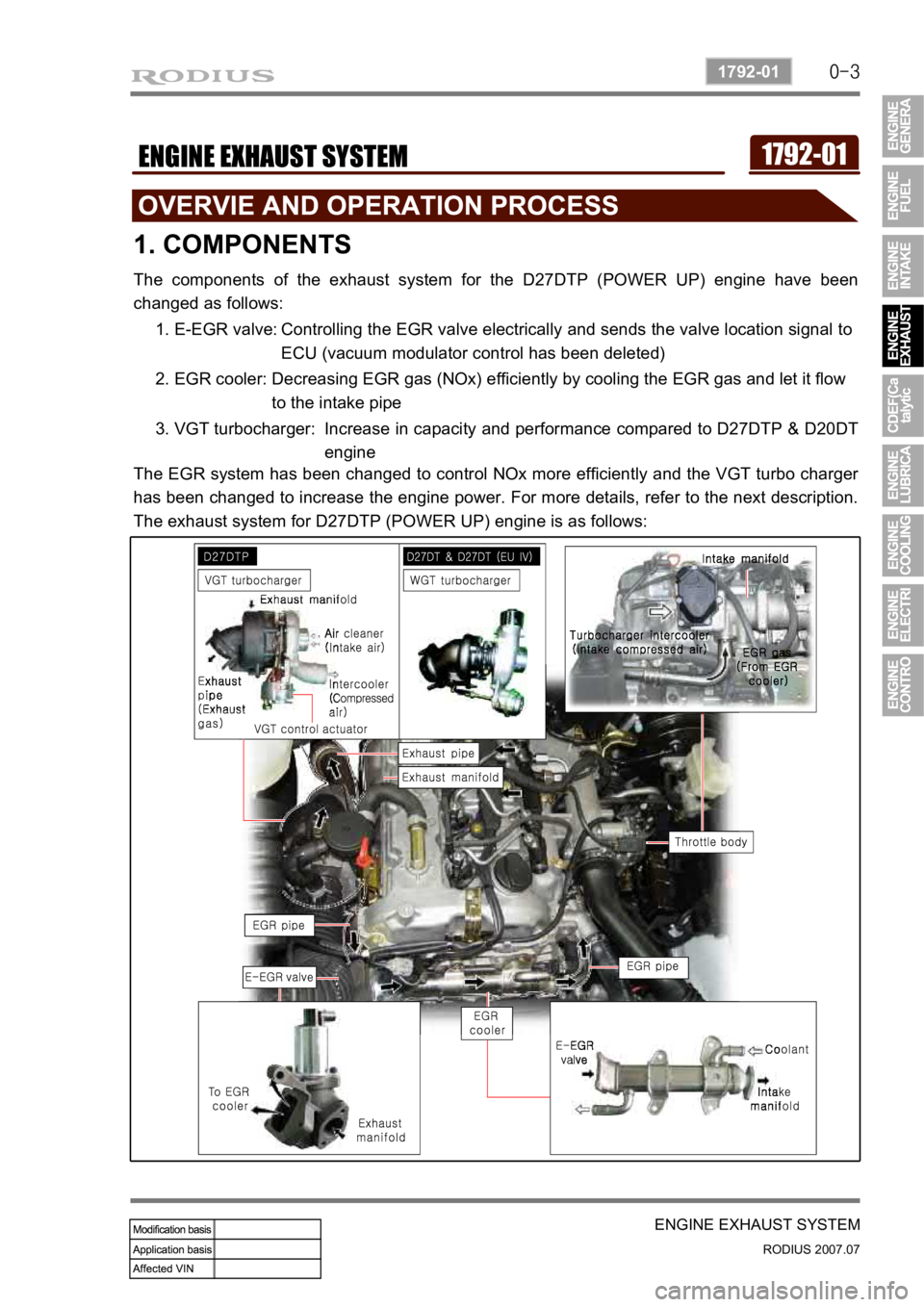
The components of the exhaust system for the D27DTP (POWER UP) engine have been
changed as follows:
1. E-EGR valve: Controlling the EGR valve electrically and sends the valve location signal to
ECU (vacuum modulator control has been deleted)
2. EGR cooler: Decreasing EGR gas (NOx) efficiently by cooling the EGR gas and let it flow
to the intake pipe
3. VGT turbocharger: Increase in capacity and performance compared to D27DTP & D20DT
engine
The EGR system has been changed to control NOx more efficiently and the VGT turbo charge
r
has been changed to increase the engine power. For more details, refer to the next description.
The exhaust system for D27DTP (POWER UP) engine is as follows:
Page 154 of 444

0-9
CDEF(Catalytic Disel Particulate Filter)
RODIUS 2007.07
0000-00
2) Sytem Composition for Soot Combustion
When the engine is running in low load range, the temperature of exhaust gas is decreased as
the amount of fuel supplied is decreased. To burnt the soot filtered in the CDPF, the control
system should be installed to check the operating range and increase the temperature o
f
exhaust gas by controlling the amount of fuel supplied and and intake air.
Two temperature sensors and one differential pressure sensor monitor the CDPF's operating
range. According to theses sensors' information, the throttle flap decreases the intake ai
r
entered to the throttle body. Also, the fuel injection pattern is added to increase the temperature
of exhaust gas for soot combustion.
There are two fuel injection patterns (pilot injection and main injection). As the CDPF is
installed, the post injection pattern is added.
3) Post Injection and Air Mass Control
When the differential pressure sensor detects the pressure difference between the front and the
rear side of CDPF, the sensor sends signal indicating the soot is acumulated and the post
injection is performed to raise the temperature of exhaust gas. The amount of fuel injected is
determined according to the temperature of exhaust gas detected by the rear temperature
<009a008c0095009a00960099005500470070008d0047009b008f008c0047009b008c00940097008c00990088009b009c0099008c00470090009a00470089008c00930096009e0047005d0057005700b6006a00530047009b008f008c004700880094009600
9c0095009b00470096008d0047008d009c008c009300470090>njected is increased to
<009900880090009a008c0047009b008f008c0047009b008c00940097008c00990088009b009c0099008c005500470070008d0047009b008f008c0047009b008c00940097008c00990088009b009c0099008c00470090009a00470096009d008c0099004700
5d0057005700b6006a00530047009b008f008c004700880094>ount of fuel injected is
decreased or not controlled.
When the engine is running in low load range, the amount of post injection and the amount of
intake air are controlled.
It is to raise the temperature by increasing the amount of fuel while decreasing the amount of
intake air.