wheel SSANGYONG RODIUS 2006 Service Manual
[x] Cancel search | Manufacturer: SSANGYONG, Model Year: 2006, Model line: RODIUS, Model: SSANGYONG RODIUS 2006Pages: 444, PDF Size: 56.32 MB
Page 33 of 444

0-9
CIRCUITundefined
4891-01
4891-01
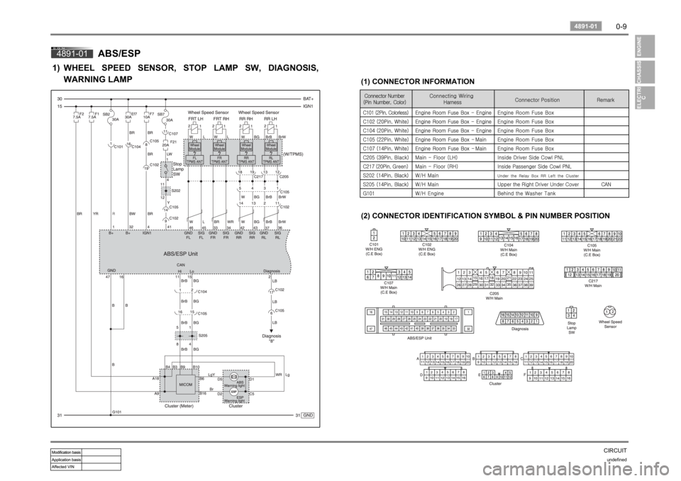
ABS/ESP
WHEEL SPEED SENSOR, STOP LAMP SW, DIAGNOSIS,
WARNING LAMP
1)
(1) CONNECTOR INFORMATION
(2) CONNECTOR IDENTIFICATION SYMBOL & PIN NUMBER POSITION
Page 66 of 444

01-6
RODIUS 2007.07
0000-00
ENGINE INFORMATION
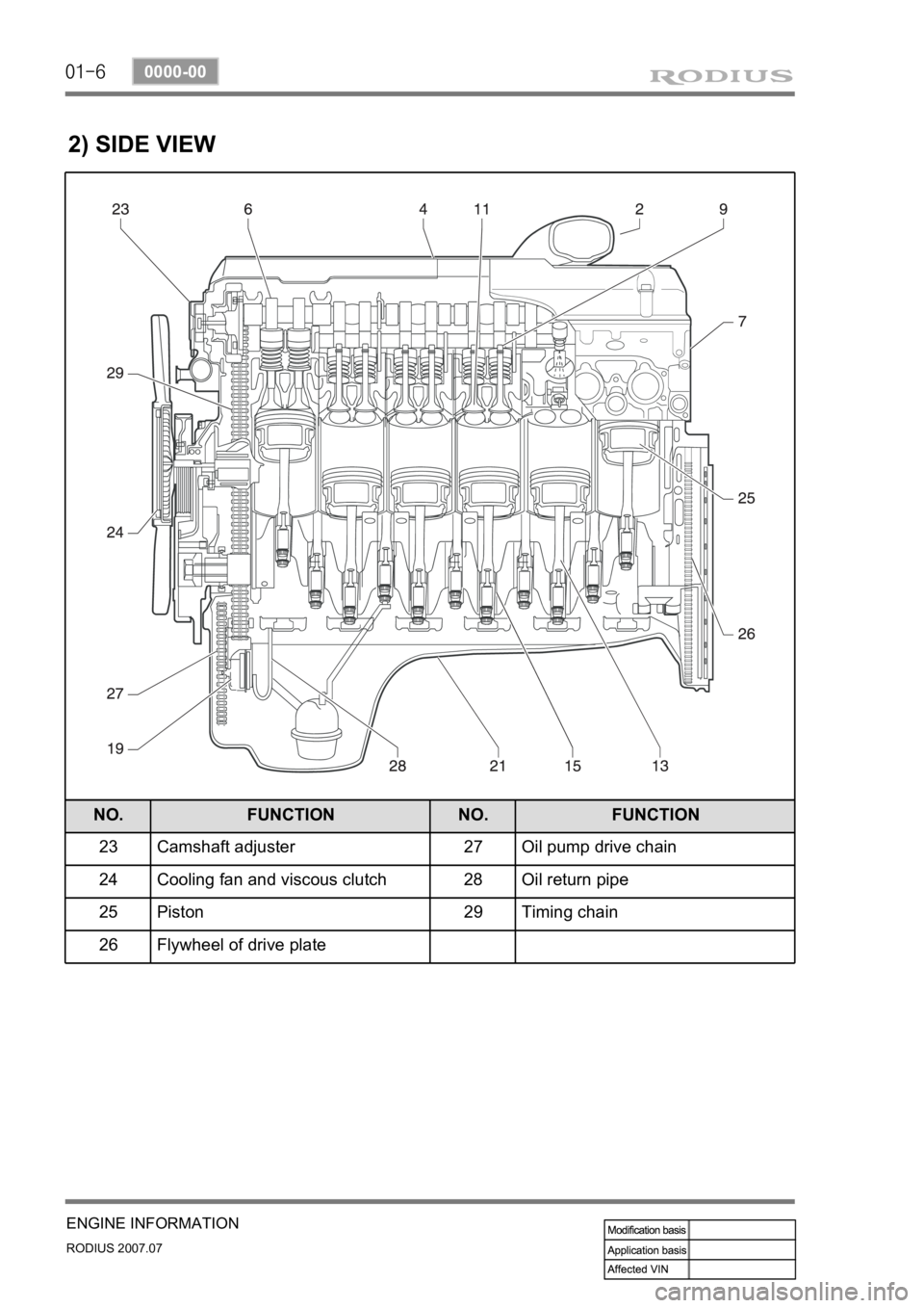
2) SIDE VIEW
NO. FUNCTION NO. FUNCTION
23 Camshaft adjuster 27 Oil pump drive chain
24 Cooling fan and viscous clutch 28 Oil return pipe
25 Piston 29 Timing chain
26 Flywheel of drive plate
Page 170 of 444

0-8
RODIUS 2007.07
0000-00
ELECTRIC GENERAL
Window switches
Outside
rearview
mirror
adjusting
and folding
switch
4WD switch and rear
washer/wiper switch
3. SWITCHES IN PASSENGER COMPARTMENT
Audio remote control switch on the steering wheel
Page 221 of 444

0-9
CLUSTER
RODIUS 2007.07
8010-10
2) Speedometer
The speedometer indicates the vehicle speed by calculating the signals from the rear right
wheel speed sensor through ABS or ESP unit.
If the speedometer pointer vibrates, stands at a certain range or sounds abnormal noise, there
could be defectives in speedometer. However, these symptoms also could be appeared when
the tire has uneven wear, different tire inflation pressures or different tire specifications.
Perform the speedometer test regarding the tolerance as described. However, it is not simila
r
simple work in field due to lack of measuring conditions such as test equipment and
preciseness.
Check the allowable tolerance of the speedometer and operations of the trip odometer by
using a tester.
Check if the speedometer pointer is shaking and the abnormal noise sounds.
Eliminate the hysteresis by tapping the speedometer. 1.
2.
3.
The allowable tolerance increases when the tires are worn or the tire pressure is out of
specified range. -
Page 252 of 444

0-4
RODIUS 2007.07
3410-01
TRANSFER CASE
1. PART TIME TRANSFER CASE OVERVIEW
By using the planetary gear sets, two-gears shift type part time transfer case achieves direct
connection when selecting 4WD “HIGH” and 2.48 of reduction gear ratio when selecting
4WD “LOW”.
The silent chain in transfer case transfers the output power to front wheels.
Simple operation of switches on instrument panel allows to shift to “2H”, “4H” and “4L”
easily while driving.
The warning lamp alarms the driver when the system is defective.
Page 257 of 444

0-9
TRANSFER CASE
RODIUS 2007.07
3410-01
Ring, snap
Ring, snap
Ring, snap
Bearing
Hub, circular
Asm. -shaft, input
Plate, thrust
Gear, sun
Snap ring
Asm. -carrier (complete)
Hub reduction
Asm. -shaft, main
Clamp hose
Hose
Filter
Asm. -coil, electric
Asm. -cam/coil hsg.
Ring, snap
Armature
Hub, lockup
Spring, sleeve return
Collar, lockup
Sprocket, driving
Spring, return
Rail, shift
Fork, shift
Asm. -fork, shift
Cam, electric shift
Spring, torsion
Spacer
Shaft, shift
Ring, retaining
Asm. -case, transfer
Barb, breather 1.
2.
3.
4.
5.
6.
7.
8.
9.
10.
11.
12.
13.
14.
15.
16.
17.
18.
19.
20.
21.
22.
23.
24.
25.
26.
27.
28.
29.
30.
31.
32.
33.
34.Decal
Shaft, output
Deflector, dust
Magnet
Ring snap
Sprocket lower
Spacer
Chain
Ring retaining
Bearing
Bearing
Cover
Bendable clip
Bolt, Metric
Seal, oil
Washer
Nut, Metric
Flange, companion
Seal, oil
Spacer
Tone wheel (upper)
Nut, Metric
Clip, “J”
Bolt, hex head
Bracket, relay mounting
Locking clip
Connector
Bolt, hex head
Capscrew, hex head
Asm. -motor, electric
Seal, oil
Plug, pipe
Sealing Compound 35.
36.
37.
38.
39.
40.
41.
42.
43.
44.
45.
46.
47.
48.
49.
50.
51.
52.
53.
54.
55.
56.
57.
58.
59.
60.
61.
62.
63.
64.
65.
66.
Page 259 of 444

0-11
TRANSFER CASE
RODIUS 2007.07
3410-01
1) 2H Mode (Rear Wheel Drive)
Power Flow ▶
Page 265 of 444

0-17
TRANSFER CASE
RODIUS 2007.07
3410-01
8. SYSTEM OPERATION
1) Transfer Case Control Unit (Tccu)
(1) 4WD Operation
TCCU is located under the front left seat and
permits the vehicle to shift from two-wheel
drive to four-wheel drive (and back shift)
according to drivers switch operation during
driving (For the shifting between 4WD HIGH
and 4WD LOW, stop the vehicle).
2H → 4H ▶
Change the 4WD switch in instrument panel from 2H to 4H.
This shift is available during driving.
“4WD HIGH” indicator in meter cluster comes on. -
-
-
When the system is defective
“4WD CHECK” warning lamp comes
on -
Change the 4WD switch in instrument panel from 4H to 2H.
This shift is available during driving.
“4WD HIGH” indicator in meter cluster goes out.
“4WD CHECK” warning lamp comes on when the system is defective. -
-
-
- 4H → 2H ▶
Page 271 of 444

0-4
RODIUS 2007.07
3010-01
CLUTCH
1. OVERVIEW
1) Driving Elements
The driving elements consist of two flat surfaces machined to a smooth finish.
One of these is the rear face of the engine flywheel and the other is the clutch cover pressure
plate. The clutch pressure plate is fitted into a clutch steel cover, which is bolted to the flywheel.
2) Driven Elements
The driven element is the clutch disc with a splined hub which is free to slide lengthwise along
the splines of the input shaft. The driving and driven elements are held in contact by spring
pressure. This pressure is exerted by a diaphragm spring in the clutch cover pressure plate
assembly.
3) Operating Elements
The clutch control system consists of the clutch pedal, clutch master cylinder, concentric slave
cylinder. This system directly releases the clutch by using hydraulic pressure while the
conventional clutch system releases the clutch by using release lever and release fork. This
system provides higher efficiency than conventional clutch system, and its durability is superior.
Adaptor (mounted on transmission case) Concentric slave cylinder pipe (mounted inside o
f
transmission) Concentric slave cylinder (mounted inside of transmission)
Page 272 of 444

0-5
CLUTCH
RODIUS 2007.07
3010-01
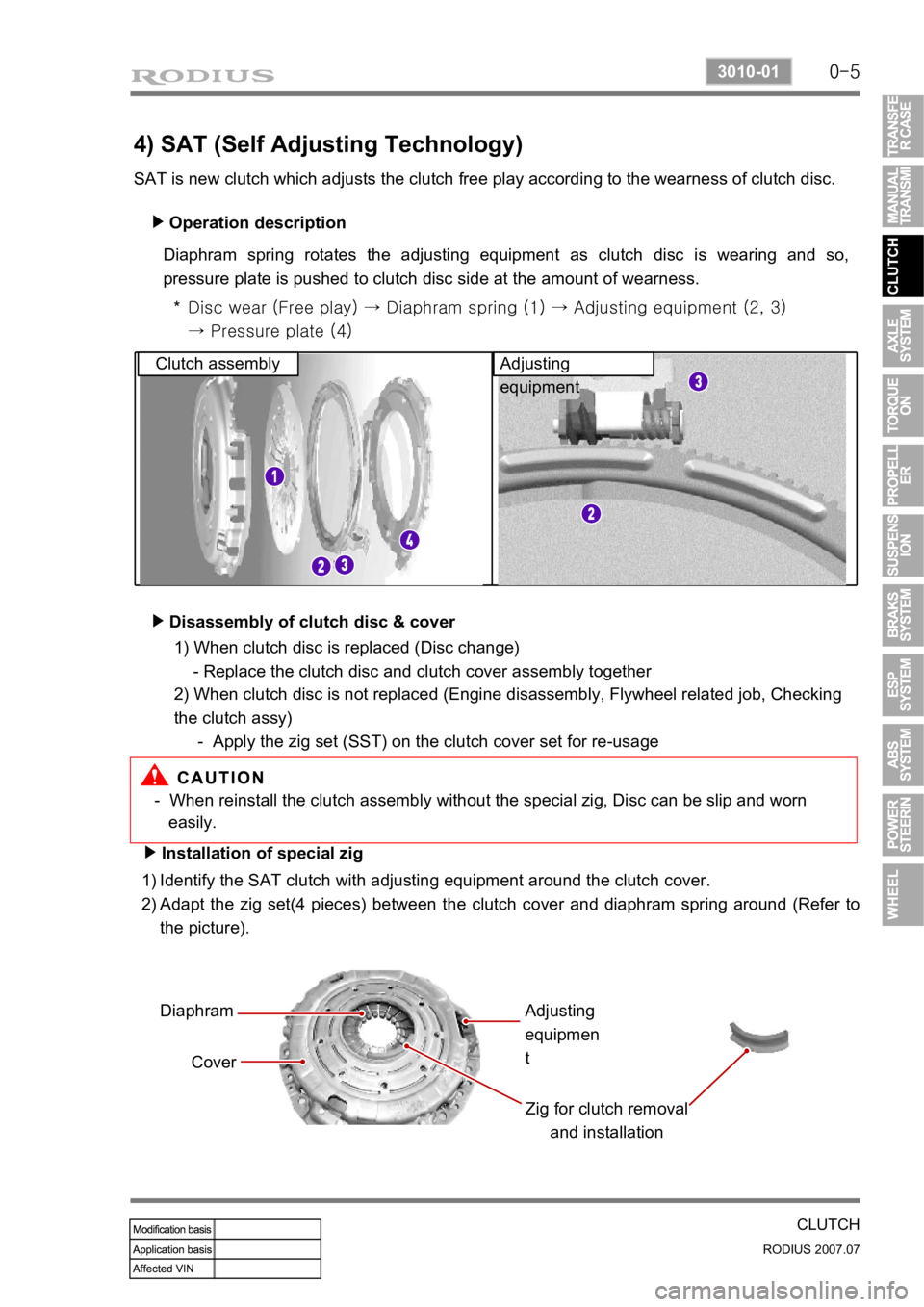
4) SAT (Self Adjusting Technology)
SAT is new clutch which adjusts the clutch free play according to the wearness of clutch disc. Operation description
▶
Diaphram spring rotates the adjusting equipment as clutch disc is wearing and so,
pressure plate is pushed to clutch disc side at the amount of wearness.
Disc wear (Free play) → Diaphram spring (1) → Adjusting equipme nt (2, 3)
→ Pressure plate (4)
*
Clutch assembly Adjusting
equipment
Disassembly of clutch disc & cover
▶
- When reinstall the clutch assembly without the special zig, Disc can be slip and worn
easily.
Installation of special zig
▶
Identify the SAT clutch with adjusting equipment around the clutch cover.
Adapt the zig set(4 pieces) between the clutch cover and diaphram spring around (Refer to
the picture).
1)
2)
Diaphram
Cover Zig for clutch removal and installationAdjusting
equipmen
t
1) When clutch disc is replaced (Disc change)
- Replace the clutch disc and clutch cover assembly together
2) When clutch disc is not replaced (Engine disassembly, Flywheel related job, Checking
the clutch assy)
- Apply the zig set (SST) on the clutch cover set for re-usage