key SSANGYONG RODIUS 2006 Owner's Manual
[x] Cancel search | Manufacturer: SSANGYONG, Model Year: 2006, Model line: RODIUS, Model: SSANGYONG RODIUS 2006Pages: 444, PDF Size: 56.32 MB
Page 210 of 444

0-37
STICS
RODIUS 2007.07
8710-01
When the dual REKES coding is
completed, the screen returns to the
below scrren. 8.
If the second key coding is finished
successfully, the below screen is
displayed.
Press [YES] button to start the
second REKES key coding. 7.
Turn off SCAN-100 and remove it from the diagnostic connector. Check if the remote
controllers are functioning properly. If the remote controllers are not properly working,
perform the REKES coding process again. 9.
Page 211 of 444

0-38
RODIUS 2007.07
8710-01
STICS
14) Theft Deterrent
(1) Description of Burglar Alarm Function
Description of Burglar Alarm Function ▶
The “LOCK” output is “ON” when receiving the “LOCK” signal from transmitter while
the ignition key is removed and all doors are closed. The armed mode is activated when the
door lock switch is locked (theft deterrent horn output: once, hazard relay output: twice).
The theft deterrent horn and hazard relay outputs are “ON” when receiving the “LOCK”
signal from the remote control key again in armed mode (theft deterrent horn output: once,
hazard relay output: twice).
When receiving “LOCK” signal from the remote control key while any of doors is not
closed, only the “LOCK” output can be done and then activates the armed ready mode
(without theft deterrent horn and hazard warning flasher). At this moment, if the ignition key
is in the ignition switch, the door unlock switch is turned “ON” or the door lock switch
is unlocked (after 0.6 seconds), cancels the armed mode and activates the normal mode.
However, in these cases, if closing the door and locking the door lock switch, the theft
deterrent horn outputs once and the hazard warning flasher outputs twice and then activates
armed mode.
When the door is not opened or the ignition key is not inserted into ignition switch for 30
seconds after receiving “UNLOCK” signal, outputs “LOCK” and then activates armed
mode (RELOCK operation). Also, at this moment, the system outputs the theft deterrent
horn and hazard warning flasher.
The armed mode will not be activated except above conditions.
Ex) The armed mode will not be activated when the door is locked by the ignition key. 1.
2.
3.
4.
5.
Page 212 of 444

0-39
STICS
RODIUS 2007.07
8710-01
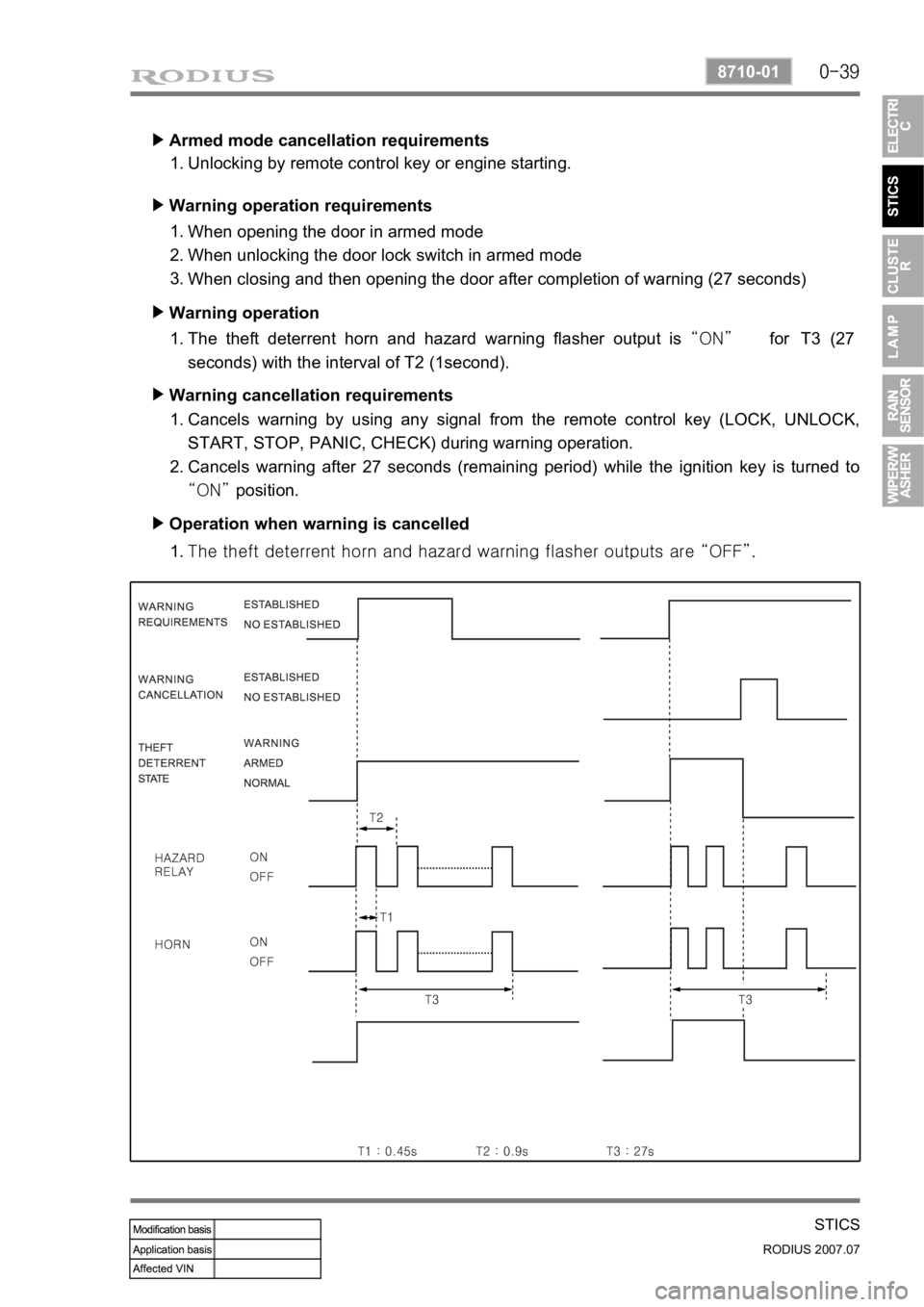
Armed mode cancellation requirements ▶
Unlocking by remote control key or engine starting. 1.
Warning operation requirements ▶
When opening the door in armed mode
When unlocking the door lock switch in armed mode
When closing and then opening the door after completion of warning (27 seconds) 1.
2.
3.
Warning operation ▶
The theft deterrent horn and hazard warning flasher output is “ON” for T3 (27
seconds) with the interval of T2 (1second). 1.
Warning cancellation requirements ▶
Cancels warning by using any signal from the remote control key (LOCK, UNLOCK,
START, STOP, PANIC, CHECK) during warning operation.
Cancels warning after 27 seconds (remaining period) while the ignition key is turned to
“ON” position. 1.
2.
Operation when warning is cancelled ▶
<007b008f008c0047009b008f008c008d009b0047008b008c009b008c00990099008c0095009b0047008f009600990095004700880095008b0047008f008800a100880099008b0047009e00880099009500900095008e0047008d00930088009a008f008c00
9900470096009c009b0097009c009b009a004700880099008c> “OFF”. 1.
Page 213 of 444

0-40
RODIUS 2007.07
8710-01
STICS
15) PANIC Warning
The PANIC warning output is “ON” (theft deterrent horn) when receiving the PANIC
signal from the remote control key (pressing PANIC button for less than 0.5 ~ 1.0 second).
The PANIC warning output is “OFF” when receiving any signal from the remote control
key during PANIC warning.
Followings are theft deterrent warnings: 1.
2.
3.
This function operates only in armed mode.
The system sends the current vehicle conditions (LOCK, engine running) when the PANIC
warning is turned off by the remote control key. 4.
5.The theft deterrent warning is canceled when receiving PANIC signal from the remote
control key during theft deterrent.
The theft deterrent warning output is “ON” when the theft deterrent conditions are
established during PANIC warning (PANIC output is “OFF”).
The PANIC warning output is “ON” when receiving the PANIC signal from the remote
control key in Armed Ready / Armed / Warning Completion / Relock Ready mode
(maintaining the theft deterrent mode). 1)
2)
3)
Page 214 of 444

0-41
STICS
RODIUS 2007.07
8710-01
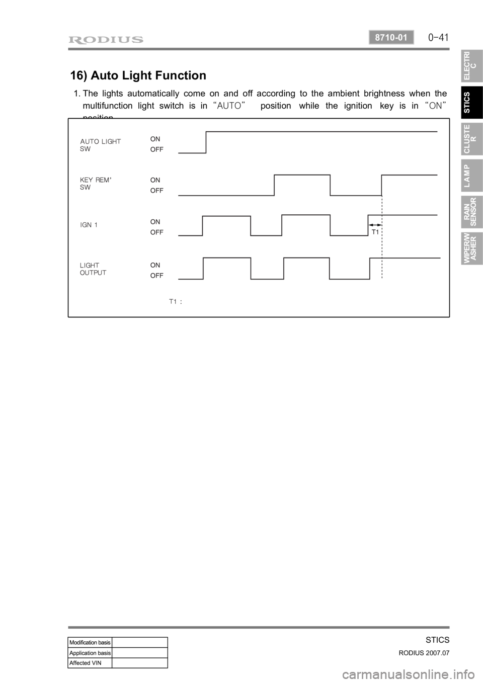
16) Auto Light Function
The lights automatically come on and off according to the ambient brightness when the
multifunction light switch is in “AUTO” position while the ignition key is in “ON”
position. 1.
Page 268 of 444

0-5
MANUAL TRANSMISSION
RODIUS 2007.07
3170-01
1) Features
All gears use the helical type and high
strength materials. 3.
The helical type gear provides less noise.
The synchronizing devices are installed in
1/2, 3/4, 5/R gears. To prevent the double
engagement, the independent interlock
devices are installed. 4.
TSM54/52 transmission uses the inertia
lock type key to make smooth gea
r
engagement and to provide silent gea
r
engagement.
The clutch release system is available to
use CSC (Concentric Slave Cylinder) o
r
Fork type according to the vehicle model.
New Rexton uses the fork type
clutch release system.
The semi-remote control type gear shift
mechanism is used to prevent incorrect
shifting. 5.
6.
Page 371 of 444
![SSANGYONG RODIUS 2006 Owners Manual 0-20
RODIUS 2007.07
6810-20
AIR CONDITIONING SYSTEM
3) AQS Operation Circuit
1. Ambient temperature switch
2. Sensor ground
3. AQS signal (Output)
4. Ground
5. IGN 2
[AQS sensor] ▶
Measure the volt SSANGYONG RODIUS 2006 Owners Manual 0-20
RODIUS 2007.07
6810-20
AIR CONDITIONING SYSTEM
3) AQS Operation Circuit
1. Ambient temperature switch
2. Sensor ground
3. AQS signal (Output)
4. Ground
5. IGN 2
[AQS sensor] ▶
Measure the volt](/img/67/57523/w960_57523-370.png)
0-20
RODIUS 2007.07
6810-20
AIR CONDITIONING SYSTEM
3) AQS Operation Circuit
1. Ambient temperature switch
2. Sensor ground
3. AQS signal (Output)
4. Ground
5. IGN 2
[AQS sensor] ▶
Measure the voltage value of AQS. (between connector terminal No. 3 and 4.)
If the measured voltage is out of 0.1 to 4.8 V, replace the AQS.
If the measured voltage is out of the specified range, replace the AQS. If it is within the
specified range, check as below.
Turn the ignition key to “ON” position.
Measure the voltage between terminal B9 and B15 on the air conditioner controller.
If the voltage value cannot be measured, check the circuit for open. If the measured value is
within the specified range, replace the FATC controller. 1.
2.
3.
4.
5.
6.
Remove the sensor and measure the resistance between terminal No. 5 and 6 on the senso
r
connector. (standard: approx. 25°C, 2.2 kΩ) In addition, if the resistance is extremely
high or low, replace the sensor.
If the measured value is out of the specified range, replace the ambient temperature sensor.
If the measured value is within the specified range, check as below.
Turn the ignition switch to ON position and measure the voltage to ambient temperature
sensor from the FATC controller connector. (standard: approx. 2 V at 25°C)
If the voltage value cannot be measured, check the circuit for open. If the measured value is
within the specified range, replace the FATC controller. 1.
2.
3.
4.[Ambient temperature sensor] ▶
Page 428 of 444

06-9
BODY EXTERIOR
RODIUS 2007.07
7115-01
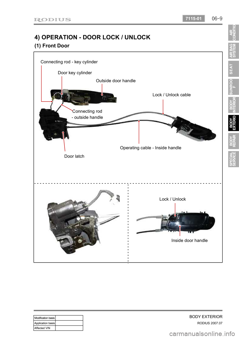
4) OPERATION - DOOR LOCK / UNLOCK
(1) Front Door
Connecting rod - key cylinder Door key cylinder Outside door handle
Lock / Unlock cable
Connecting rod
- outside handle
Door latch Operating cable - Inside handle
Lock / Unlock Inside door handle
Page 429 of 444

06-10
RODIUS 2007.07
7115-01
BODY EXTERIOR
▶Operating Process
Operation of lock button Operating cable Latch lock / Unlock
Operation of Inside handle Operating cable Latch open mode
Operation of outside handle Connecting rod - outside handle Latch open mode Insert key & operation Connecting rod - key cylinder Latch lock / Unlock Lock / Unlock (Inside door handle)
Inside handle
Outside handle Key cylinder
Page 433 of 444

06-14
RODIUS 2007.07
7115-01
BODY EXTERIOR
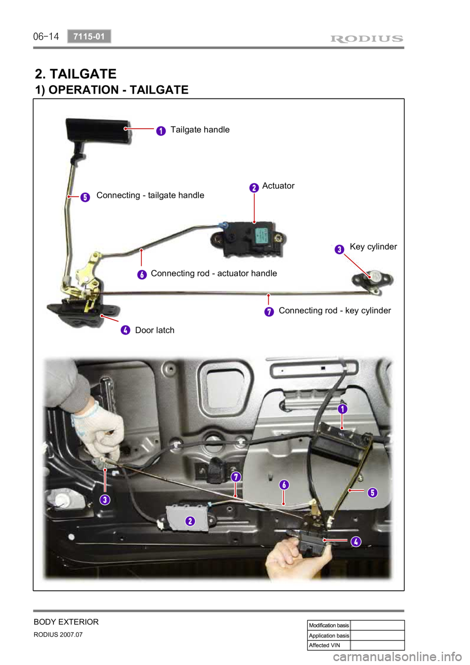
2. TAILGATE
1) OPERATION - TAILGATE
Tailgate handle Actuator
Key cylinder
Door latch
Connecting - tailgate handle
Connecting rod - actuator handle Connecting rod - key cylinder