SSANGYONG RODIUS 2007 Service Manual
RODIUS 2007
SSANGYONG
SSANGYONG
https://www.carmanualsonline.info/img/67/57524/w960_57524-0.png
SSANGYONG RODIUS 2007 Service Manual
Page 1 of 465
GENERAL INFORMATION
0000-00
GENERAL INFORMATION
GENERAL INFORMATION1. HOW TO READ ELECTRICAL WIRING
DIAGRAM...............................................
3
Page 3 of 465

0-3
GENERAL INFORMATION
RODIUS 2006.09
0000-00
GENERAL INFORMATION
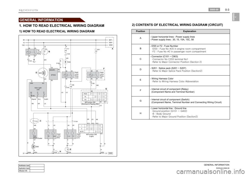
1. HOW TO READ ELECTRICAL WIRING DIAGRAM
Position Explanation
A- Upper horizontal lines : Power supply lines
- Power supply lines : 30, 15, 15A, 15C, 58
B- Ef20 or F2 : Fuse Number
·Ef20 : Fuse No #20 in engine room compartment
·F2 : Fuse No #2 in passenger room compartment
C- Connector (C101 ~ C903)
·Connector No C203 terminal No1
·Refer to Major Connector Position (Section 2)
D- S201 : Splice pack (S201 ~ S207)
·Refer to Major Splice Pack Position (Section2)
E- Wiring Harness Color
·Refer to Wiring Harness Color Abbreviation
F- Internal circuit of component (Relay)
(Component Name and Terminal Number)
G- Internal circuit of component (Switch)
(Component Name, Terminal Number and Connecting Wiring Circuit)
H- Lower horizontal line : Ground line
·Ground position (G101 ~ G402)
·B : Body Ground
·Refer to Major Ground Position (Section2)
1) HOW TO READ ELECTRICAL WIRING DIAGRAM2) CONTENTS OF ELECTRICAL WIRING DIAGRAM (CIRCUIT)
Page 168 of 465
01-3
FUSE AND RELAY
RODIUS 2006.09
0000-00
8410-01FUSES AND RELAYS
1. OVERVIEW
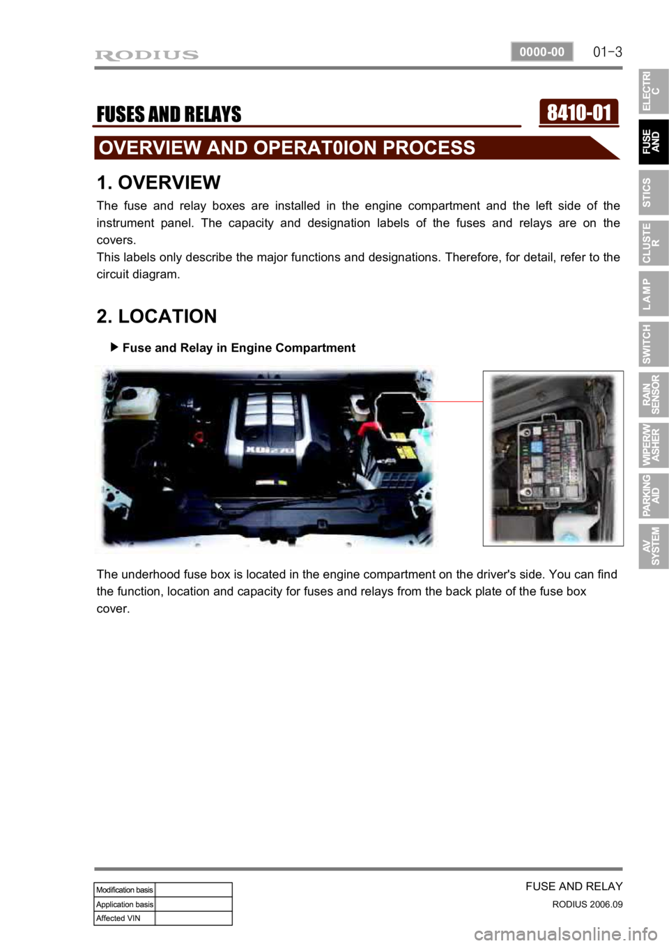
The fuse and relay boxes are installed in the engine compartment and the left side of the
instrument panel. The capacity and designation labels of the fuses and relays are on the
covers.
This labels only describe the major functions and designations. Therefore, for detail, refer to the
circuit diagram.
2. LOCATION
Fuse and Relay in Engine Compartment
▶
The underhood fuse box is located in the engine compartment on the driver's side. You can find
the function, location and capacity for fuses and relays from the back plate of the fuse box
cover.
Page 172 of 465
01-7
FUSE AND RELAY
RODIUS 2006.09
0000-00
1) D27DT - I
4. CIRCUIT DIAGRAM FOR FUSES AND RELAYS
Page 182 of 465
0-9
STICS
RODIUS 2006.09
8710-01
(2) Rain Sensor Coupled Wiper
If equipped with RE-STICS rain sensor, has following operation system.
System layout ▶
This vehicle has a different wiper control logic compared to other models. As shown in the
system diagram, the rain sensor unit does not control wiper directly. The rain sensor unit sends
infrared rays signal through LED and then receives it with photo diode and then sends the
returned signal to STICS and the STICS controls the wipers directly.
For more details, refer to rain sensing wiper section in this manual.
Page 222 of 465
0-10
RODIUS 2006.09
8010-10
CLUSTER
3) Fuel Level Gauge
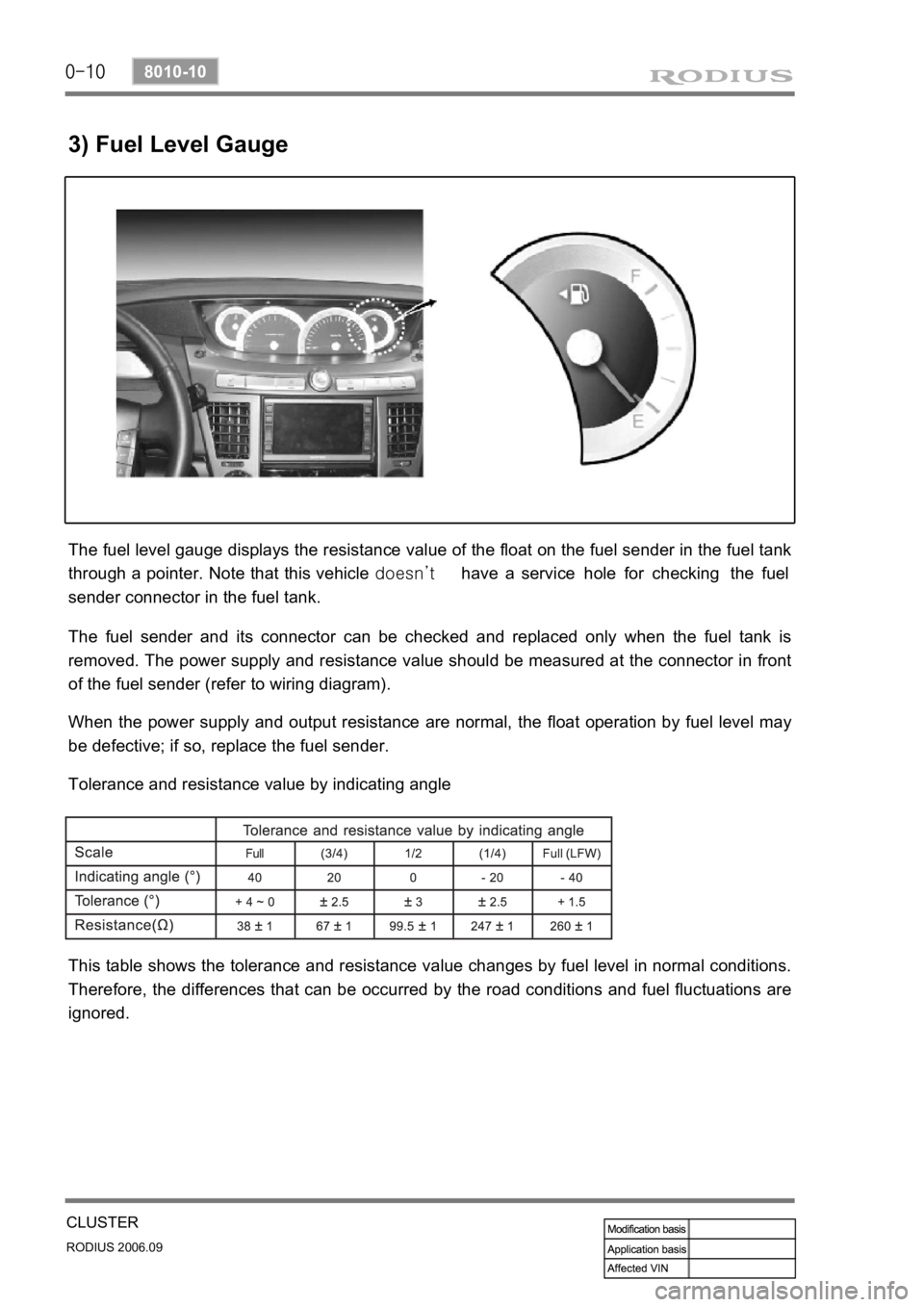
The fuel level gauge displays the resistance value of the float on the fuel sender in the fuel tank
through a pointer. Note that this vehicle doesn’t have a service hole for checking the fuel
sender connector in the fuel tank.
The fuel sender and its connector can be checked and replaced only when the fuel tank is
removed. The power supply and resistance value should be measured at the connector in front
of the fuel sender (refer to wiring diagram).
When the power supply and output resistance are normal, the float operation by fuel level may
be defective; if so, replace the fuel sender.
Tolerance and resistance value by indicating angle
This table shows the tolerance and resistance value changes by fuel level in normal conditions.
Therefore, the differences that can be occurred by the road conditions and fuel fluctuations are
ignored.
Page 225 of 465
0-13
CLUSTER
RODIUS 2006.09
8010-10
5. CIRCUIT DIAGRAM OF INDICATOR DISPLAY
Page 246 of 465
0-10
RODIUS 2006.09
8610-11
RAIN SENSOR
6. RAIN SENSOR RELATED CIRCUIT
The rain sensor has one connector with 4 pins and each pin has following function as shown in
the circuit diagram.
However, in this vehicle, the terminal No. 1 and No. 2 are for communications between STICS
and the rain sensor; the No. 1 terminal sends the detected value from the rain sensor to STICS
then the STICS drives wiper motor.
to the rain sensor to recognize whether it is actual rain or it is in rain sensing wiper operation
mode.
No.2 terminal sends the wiper and washer operation information such as
washer operation mode,
MIST mode, or
AUTO wiper position -
-
-
Page 251 of 465
0-7
WIPER/WASHER SYSTEM
RODIUS 2006.09
0000-00
4. CIRCUIT DIAGRAM OF WIPER & WASHER
Page 263 of 465
0-14
RODIUS 2006.09
8790-04
PARKING AID SYSTEM
7. CIRCUIT DIAGRAM


