heating SSANGYONG RODIUS 2007 Service Manual
[x] Cancel search | Manufacturer: SSANGYONG, Model Year: 2007, Model line: RODIUS, Model: SSANGYONG RODIUS 2007Pages: 465, PDF Size: 56.32 MB
Page 26 of 465

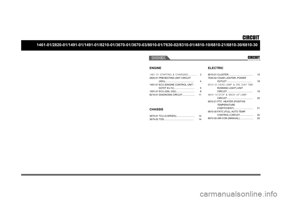
CIRCUIT
1461-01/2820-01/1491-01/1491-01/8210-01/3670-01/3670-03/8010-01/7630-02/8310-01/4810-10/6810-21/6810-30/6810-30
CIRCUIT
ENGINE
CHASSIS3670-01 TCU (5-SPEED)............................
3670-03 TOD.............................................
ELECTRIC8010-01 CLUSTER.....................................
7630-02 CIGAR LIGHTER, POWER
OUTLET......................................
8310-01 HEAD LAMP & DRL (DAY TIME
RUNNING LIGHT) UNIT
CIRCUIT.......................................
4810-10 STOP & BACK-UP LAMP
CIRCUIT.......................................
6810-21 PTC HEATER (POSITIVE
TEMPERATURE
COEFFICIENT).............................
6810-30 FATC (FULL AUTO TEMP.
CONTROL) CIRCUIT....................
6810-30 AIR-CON (MANUAL)..................... 12
1415
18
19
20
21
22
25 1461-01 STARTING & CHARGING............
2820-01 PREHEATING UNIT CIRCUIT
(XDi))............................................
1491-01 ECU (ENGINE CONTROL UNIT -
D27DT EU IV)...............................
1491-01 ECU (GSL G32)............................
8210-01 DIAGNOSIS CIRCUIT...................3
4
5
8
11
Page 29 of 465

0-4RODIUS 2006.09
2820-01
CIRCUIT2820-01
PREHEATING UNIT CIRCUIT (XDi)
1) CONNECTOR INFORMATION
2) CONNECTOR IDENTIFICATION SYMBOL & PIN NUMBER POSITION
Page 70 of 465

05-3
ENGINE EXHAUST SYSTEM
RODIUS 2006.09
0000-00
2420-01ENGINE EXHAUST SYSTEM
1. OVERVIEW OF EXHAUST SYSTEM
When you are inspecting or replacing exhaust system components, make sure there is
adequate clearance from all points on the underbody to avoid possible overheating of the
floor panel and possible damage to the passenger compartment insulation and trim
materials.
Check the complete exhaust system and the nearby body areas and trunk lid for broken,
damaged, missing or mispositioned parts, open seams, holes, loose connections, or othe
r
deterioration which could permit exhaust fumes to seep into the trunk may be an indication
of a problem in one of these areas. Any defects should be corrected immediately. -
2. OVERVIEW OF MUFFLER
Aside from the exhaust manifold connection, the exhaust system uses a flange and seal joint
design rather than a slip joint coupling design with clamp and U-bolts.
If hole, open seams, or any deterioration is discovered upon inspection of the front muffler and
pipe assembly, the complete assembly should be replace, the complete assembly should be
replaced.
The same procedure is applicable to the rear muffler assembly. Heat shields for the front and
rear muffler assembly and catalytic converter protect the vehicle and the environment from the
high temperatures that the exhaust system develops.
3. OVERVIEW OF CATALYTIC CONVERTER
When jacking or lifting the vehicle from the body side rails, be certain that the lift pads do
not contact the catalytic converter, as this could damage the catalytic converter. -
Use of anything other than unleaded fuel will damage the catalyst in the catalytic
converter. -
The catalytic converter are emission-control devices added to the exhaust system to
reduce pollutants from the exhaust pipes.
The oxidation catalyst is coated with a catalytic material containing platinum and
palladium, which reduces levels of hydrocarbon (HC) and carbon monoxide (CO) from
the exhaust gas. The three-way catalyst has coatings which contain platinum and
rhodium, which additionally lower the levels of oxides of nitrogen (NOx). ·
·
Page 77 of 465

07-6
RODIUS 2006.09
0000-00
COOLING SYSTEM
1. GENERAL DESCRIPTION
The cooling system maintains the engine temperature at an efficient level during all engine
operating conditions. When the engine is cold, the cooling system cools the engine slowly o
r
not at all. This slow cooling of the engine allows the engine to warm up quickly. The cooling
system includes a radiator and recovery subsystem, cooling fans, a thermostat and housing, a
water pump, and a water pump drive belt. The timing belt drives the water pump.
All
components must function properly for the cooling system to operation. The water pump draws
the coolant from the radiator.
The coolant then circulates through water jackets in the engine block, the intake manifold, and
the cylinder head. When the coolant reaches the operating temperature of the thermostat, the
thermostat opens. The coolant then goes back to the radiator where it cools. This system
directs some coolant through the hoses to the heat core. This provides for heating and
defrosting. The coolant reservoir is connected to the radiator to recover the coolant displaced
by expansion from the high temperatures. The coolant reservoir maintains the correct coolant
level. The cooling system for this vehicle has no radiator cap or filler neck. The coolant is
added to the cooling system through the coolant reservoir.
Page 390 of 465

0-18
RODIUS 2006.09
6810-20
AIR CONDITIONING SYSTEM
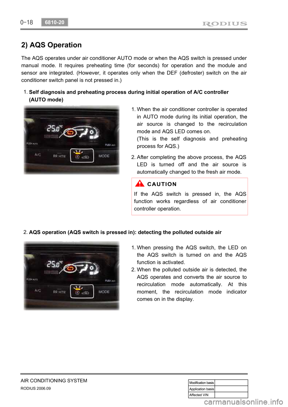
2) AQS Operation
The AQS operates under air conditioner AUTO mode or when the AQS switch is pressed under
manual mode. It requires preheating time (for seconds) for operation and the module and
sensor are integrated. (However, it operates only when the DEF (defroster) switch on the ai
r
conditioner switch panel is not pressed in.)
Self diagnosis and preheating process during initial operation of A/C controller
(AUTO mode)
1.
AQS operation (AQS switch is pressed in): detecting the polluted outside air
2.
When the air conditioner controller is operated
in AUTO mode during its initial operation, the
air source is changed to the recirculation
mode and AQS LED comes on.
(This is the self diagnosis and preheating
process for AQS.)
1.
After completing the above process, the
AQS
LED is turned off and the air source is
automatically changed to the fresh air mode.
2.
If the AQS switch is pressed in, the AQS
function works regardless of air conditioner
controller operation.
When pressing the AQS switch, the LED on
the AQS switch is turned on and the
AQS
function is activated.
When the polluted outside air is detected, the
AQS operates and converts the air source to
recirculation mode automatically. At this
moment, the recirculation mode indicato
r
comes on in the display.
1.
2.