table SSANGYONG RODIUS 2012 Service Manual
[x] Cancel search | Manufacturer: SSANGYONG, Model Year: 2012, Model line: RODIUS, Model: SSANGYONG RODIUS 2012Pages: 715, PDF Size: 79.36 MB
Page 136 of 715

01-210000-00
9. TIGHTENING TORQUE OF STANDARD BOLTS
Tightening Torque By Bolt Specification ▶
Metric bolt strength is embossed on the head
of each bolt. The strength of bolt can be
classified as 4T, 7T, 8.8T, 10.9T, 11T and
12.9T in general.
Observe standard tightening torque during
bolt tightening works and can adjust torque to
be proper within 15 % if necessary. Try not to
over max. allowable tightening torque if not
required to do so. 1.
2.Determine extra proper tightening torque if
tightens with washer or packing.
If tightens bolts on the below materials, be
sure to determine the proper torque. 3.
4.
Aluminum alloy: Tighten to 80 % o
f
above torque table.
Plastics: Tighten to 20 % of above torque
table. ·
·
Page 153 of 715

01-110000-00
5. STANDARD BOLTS SPECIFICATIONS
Metric bolt strength is embossed on the head of each bolt. The strength of bolt can be
classified as 4T, 7T, 8.8T, 10.9T, 11T and 12.9T in general.
Observe standard tightening torque during bolt tightening works and can adjust torque to be
proper within 15 % if necessary. Try not to over max. allowable tightening torque if not required
to do so.
Determine extra proper tightening torque if tightens with washer or packing.
If tightens bolts on the below materials, be sure to determine the proper torque. 1)
2)
3)
4)
Aluminum alloy: Tighten to 80 % of above torque table.
Plastics: Tighten to 20 % of above torque table. -
-
Page 195 of 715

02-38
4) Features
Reduced vibration noise from the powertrain by blocking the torsional vibrations
Enhanced vehicle silence and riding comforts: reduced engine torque fluctuation
Reduced shifting shocks
Smooth acceleration and deceleration -
-
-
-
5) Advantages
Improved torque response by using 3-stage type spring: Strengthens the torque response in all
ranges (low, medium, and high speed) by applying respective spring constant at each range.
Stable revolution of the primary and secondary wheel by using planetary gear: Works as
auxiliary damper against spring changes
Less heat generation due to no direct friction against spring surface: Plastic material is covered
on the spring outer surface
Increased durability by using plastic bushing (extends the lifetime of grease) -
-
-
-
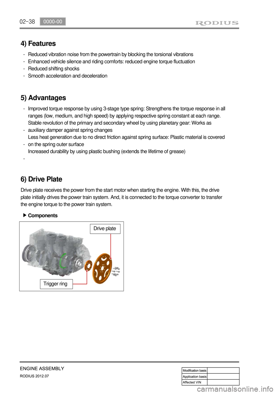
6) Drive Plate
Drive plate receives the power from the start motor when starting the engine. With this, the drive
plate initially drives the power train system. And, it is connected to the torque converter to transfer
the engine torque to the power train system.
Trigger ring
Drive plate
Components ▶
Page 201 of 715

02-44
NoConnecting
rod/ Bore
diameter in big
endUpper bearing Lower bearing
Journal
diameter of
crank pinOil
clearance o
f
bearing
GradeBearing
thicknessGradeBearing
thickness
1
54.600 R 1.804
B 1.812
50.935 0.017
1.808 1.815 0.063
2
Y 1.808
Y 1.809 0.016
54.614 1.812 1.812
50.960 0.062
3
B 1.812
R 1.806 0.015
1.816 1.809 0.061
Min. 0.015
Max. 0.063
(3) Selection of crankshaft pin journal bearing
The connecting rod bearing contains 3 sets of 3 grades in upper and lower sections.
Three sets in the table below have nearly same oil clearance (0.015~0.063 mm) of bearing.
Identification: Coloe mark on bearing side surface -
-
-
Oil clearance of connecting rod bearing
Page 337 of 715

15-12
(2) Fuel injection control
a. Multi injection
Fuel injection process consists of 3 steps: Main Injection, Pilot Injection, Post Injection
This is the injection before main injection. This consists of 1st and 2nd pilot injection, and Pre-injection.
The steps are normally used to control the NOx, noise, idle stability and engine vibration. Inject a small
amount of fuel before main injection prevents the instant high combustion temperature. It reduces the
NOx and decreases the engine noise and vibration. The main injection produces the actual output. The
vehicle output is based on the main injection. The post injection is the injection process after main
injection and consists of ‘After injection”, “Post 1 injection” and “Post 2 injection”. All of post
injections are to reduce the PM and harmful exhaust gas. The post injection does not make the actual
output. The post injection activates the fuel by injecting the fuel to the incompletely combusted gas after
primary combustion. Through the process, the PM and smoke in the exhaust gas could be reduced.
There are totally 7 injections as shown in the figure. However, all of 7 injections are not performed during
driving because it decreases the fuel economy. Totally 5 injections can be performed in one cycle.
InjectionFunction
MainProduces engine power
Pilot 1Reduces PM by injecting before
main injection.AfterPM control
Pilot 2Reduces NOx and noise by
shortening main injection delay
due to flammability Post 1Reduces PM by enabling fuel
activation.
PreControls NOx emission level,
Combustion noise and
Stable idle Post 2Activates CDPF by increasing
exhaust gas temperature and
supplying reduction material
Page 402 of 715

08-51452-01
1. CHARGING SYSTEM OPERATION
Alternators use a new type of regulator that incorpo-rates a diode trio. A Delta stator, a rectifier
bridge, and a rotor with slip rings and brushes are electrically similar to earlier alternators.
A conventional pulley and fan are used. There is no test hole.
1) Charging Time Required
The time required to charge a battery will vary depending upon the following factors:
Size of Battery ▶
A Completely discharged large heavy-duty battery required more than twice the
recharging time as a completely discharged small passenger car battery. -
Temperature ▶
A longer time will be needed to charge any battery at -18°C (0°F) than at 27°C (80°F).
When a fast charger is connected to a cold battery, the current accepted by the battery
will be very low at first. The battery will accept a higher current rate as the battery warms. -
Charger Capacity ▶
A charger which can supply only 5 amperes will require a much longer charging period
than a charger that can supply 30 amperes or more. -
State-of-Charge ▶
A completely discharged battery requires more than twice as much charge as a onehalf
charged battery. Because the electrolyte is nearly pure water and a poor conductor in a
completely discharged battery, the current accepted by the battery is very low at first.
Later, as the charging current causes the electrolyte acid content to increase, the charging
current will likewise increase. -
2. STARTING SYSTEM OPERATION
The engine electrical system includes the battery, the ignition, the starter, the alternator, and all
the related wiring. Diagnostic tables will aid in troubleshooting system faults. When a fault is
traced to a particular component, refer to that component section of the service manual. The
starting system circuit consists of the battery, the starter motor, the ignition switch, and all the
related electrical wiring. All of these components are connected electrically.
Page 405 of 715

09-31522-16
1. ENGINE DATA DISPLAY TABLE
Page 445 of 715

02-14
▶ Speed Sensitive INT (Intermittent) Wiper
For STICS without rain sensor, perform the following operation:
1. Controls the wiper intermittent operation by the values from vehicle speed and volume.
Calculates and converts the Intermittent interval automatically by using the vehicle speed and
<00700075007b0047007d00760073007c0074006c0047009e008f008c00950047009b008f008c00470090008e00950090009b0090009600950047009a009e0090009b008a008f00470090009a004700900095004702c80076007502c9004700970096009a00
90009b009000960095004700880095008b0047009b008f008c> INT switch is in “ON”
position (the engine is running).
The wipers are operated in vehicle speed sensitive mode when turning the INT switch to
<02c80076007502c9004700970096009a0090009b0090009600950047009e0090009b008f0047009b008f008c0047008c0095008e00900095008c00470099009c0095009500900095008e0047009600990047009a009b00880099009b00900095008e004700
9b008f008c0047008c0095008e00900095008c0047009e0090>th the INT switch positioned
“ON”.
<00700095009b008c009900940090009b009b008c0095009b004700900095009b008c0099009d008800930047004f0088009b004700570047009200940056008f005000610047005a004700b7004700570055005c004700a5004700580060004700b7004700
590047009a008c008a00960095008b009a> -
-
-
2. Vehicle speed calculation
[Input the vehicle speed]
It is calculated by the numbers of input pulses for one second.
1 [pulses/sec] = 60 [km/h] x 60 [sec] / 637 pulses = 1.41 [km/h]
3. VOLUME calculation
Calculates the INT VOLUME with 5 grades as shown in the table in next page. -
4. Pause time calculation
Pause time: the duration that wipers are stopped at parking position
Elapsed time: the duration after the wiper motor started to operate from parking position
The pause time is calculated by the vehicle speed and VOLUME value as shown in the table
in next page. -
-
-
If the pause time is below 1.0 second, the wipers operate without pause.
If the pause time is over 1.5 seconds, the wipers operate intermittently. ·
·
Page 592 of 715

07-94411-01
5. DIMENSIONS OF REAR SUSPENSION
(1) Shock Absorber
Keep the suitable distance when compressed and extended.
Minimum length should be 10 mm longer than the fully compressed length. -
-
Dimension ▶
Maximum operating length Minimum operating length
Operating distance
487.0 ± 0.3 (mm) 326.0 + 0.3 (mm) 160.4 (mm)
Marking ▶
X: Part number
Y: Lot number
Ex:
3C12
12.............(Day)
3...............(Month)
2003......(Year)
Page 619 of 715

09-114891-01
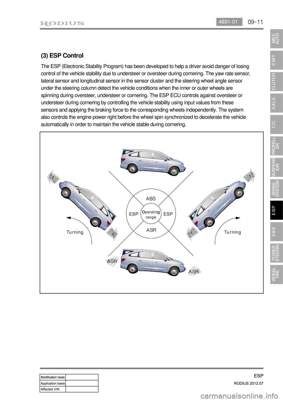
(3) ESP Control
The ESP (Electronic Stability Program) has been developed to help a driver avoid danger of losing
control of the vehicle stability due to understeer or oversteer during cornering. The yaw rate sensor,
lateral sensor and longitudinal sensor in the sensor cluster and the steering wheel angle sensor
under the steering column detect the vehicle conditions when the inner or outer wheels are
spinning during oversteer, understeer or cornering. The ESP ECU controls against oversteer or
understeer during cornering by controlling the vehicle stability using input values from these
sensors and applying the braking force to the corresponding wheels independently. The system
also controls the engine power right before the wheel spin synchronized to decelerate the vehicle
automatically in order to maintain the vehicle stable during cornering.