Gear SSANGYONG RODIUS 2012 Owner's Manual
[x] Cancel search | Manufacturer: SSANGYONG, Model Year: 2012, Model line: RODIUS, Model: SSANGYONG RODIUS 2012Pages: 715, PDF Size: 79.36 MB
Page 313 of 715

14-32412-02
1. CAUTIONS
Standard pattern of soot accumulation ▶
(1) Abnormal Soot Accumulation (2) Normal Soot Combustion
Cautions to protect the catalyst filter ▶
Use the designated fuel only.
Observe the recommended service intervals of engine oil.
Check the engine oil level frequently and add if necessary.
Do not idle the vehicle unnecessarily.
Do not turn off the engine while the vehicle is running.
Do not shift the gear selector lever to neutral when going downhill.
Do not use improper engine oil or fuel additives.
Do not drive for a long time when the warning lamp is illuminated.
Make sure no flammable material, such as dry grass or tissue paper, contacts with the catalyst
filter while the vehicle is parked.
For the vehicles used in urban traffic, driving on the expressways for more than 1 hour at least
once per week is needed so that the PM inside CDPF isn't collected to one side only. -
-
-
-
-
-
-
-
-
-
Page 328 of 715

15-30000-00
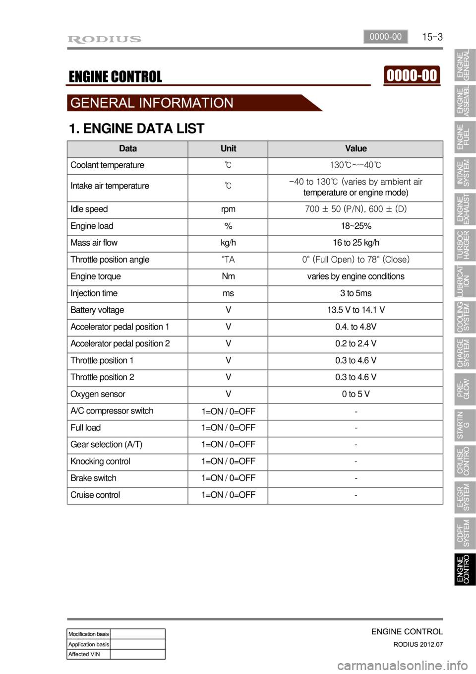
1. ENGINE DATA LIST
Data Unit Value
Coolant temperature℃ 130℃~-40℃
Intake air temperature℃ -40 to 130℃ (varies by ambient air
temperature or engine mode)
Idle speed rpm 700 ± 50 (P/N), 600 ± (D)
Engine load % 18~25%
Mass air flow kg/h 16 to 25 kg/h
Throttle position angle°TA 0° (Full Open) to 78° (Close)
Engine torque Nm varies by engine conditions
Injection time ms 3 to 5ms
Battery voltage V 13.5 V to 14.1 V
Accelerator pedal position 1 V 0.4. to 4.8V
Accelerator pedal position 2 V 0.2 to 2.4 V
Throttle position 1 V 0.3 to 4.6 V
Throttle position 2 V 0.3 to 4.6 V
Oxygen sensor V 0 to 5 V
A/C compressor switch
1=ON / 0=OFF -
Full load 1=ON / 0=OFF -
Gear selection (A/T) 1=ON / 0=OFF -
Knocking control 1=ON / 0=OFF -
Brake switch 1=ON / 0=OFF -
Cruise control 1=ON / 0=OFF -
Page 343 of 715

15-18
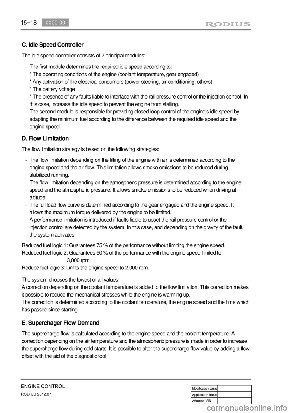
C. Idle Speed Controller
The idle speed controller consists of 2 principal modules:
The first module determines the required idle speed according to:
* The operating conditions of the engine (coolant temperature, gear engaged)
* Any activation of the electrical consumers (power steering, air conditioning, others)
* The battery voltage
* The presence of any faults liable to interface with the rail pressure control or the injection control. In
this case, increase the idle speed to prevent the engine from stalling.
The second module is responsible for providing closed loop control of the engine's idle speed by
adapting the minimum fuel according to the difference between the required idle speed and the
engine speed. -
-
D. Flow Limitation
The flow limitation strategy is based on the following strategies:
The flow limitation depending on the filling of the engine with air is determined according to the
engine speed and the air flow. This limitation allows smoke emissions to be reduced during
stabilized running.
The flow limitation depending on the atmospheric pressure is determined according to the engine
speed and the atmospheric pressure. It allows smoke emissions to be reduced when driving at
altitude.
The full load flow curve is determined according to the gear engaged and the engine speed. It
allows the maximum torque delivered by the engine to be limited.
A performance limitation is introduced if faults liable to upset the rail pressure control or the
injection control are detected by the system. In this case, and depending on the gravity of the fault,
the system activates: -
-
-
-
Reduced fuel logic 1: Guarantees 75 % of the performance without limiting the engine speed.
Reduced fuel logic 2: Guarantees 50 % of the performance with the engine speed limited to
3,000 rpm.
Reduce fuel logic 3: Limits the engine speed to 2,000 rpm.
The system chooses the lowest of all values.
A correction depending on the coolant temperature is added to the flow limitation. This correction makes
it possible to reduce the mechanical stresses while the engine is warming up.
The correction is determined according to the coolant temperature, the engine speed and the time which
has passed since starting.
E. Superchager Flow Demand
The supercharge flow is calculated according to the engine speed and the coolant temperature. A
correction depending on the air temperature and the atmospheric pressure is made in order to increase
the supercharge flow during cold starts. It is possible to alter the supercharge flow value by adding a flow
offset with the aid of the diagnostic tool
Page 489 of 715

06-4
4WD Switch, Headlamp
Leveling Switch, Rear Wipe
Switch
Outside Rearview
Mirror
Adjusting/Folding
Switches
Remote Control Switches on Steering Wheel
Window switch
1. LAYOUT
Volume button
Seek buttonManual gear shift
down switch
Power buttonManual gear shift
up switch
Mode button
Mute button
Bluetooth switch
Page 512 of 715

09-58790-01
2. CAUTIONS
The parking aid system is just a supplemental device to help your parking.
Always keep the safety precautions.
Do not press or shock the sensors by hitting or using a high-pressure water gun while
washing, since it may damage the sensors.
If the system is in normal operating condition, a short beep sounds when the shift lever is
moved into "R" position with the ignition key "ON".
If the system is defective, the warning buzzer sounds for 3 seconds when moving the gear
<009a008f0090008d009b00470093008c009d008c00990047009b0096004702c8007902c9004700970096009a0090009b0090009600950047009e0090009b008f0047009b008f008c00470090008e00950090009b0090009600950047007600750055004700
69008c0047008a00880099008c008d009c0093004700950096>t to confuse this and the parking
aid alarm (in 50 cm). 1.
2.
3.
4.
5.
· Note that the display does not show everything in the rear area. Always check
nobody, especially animals and children, is behind the vehicle when parking or
reversing.
· If you can not properly check the vehicle behind, get out of the vehicle and then
visually check it.
The parking aid system will not work or improperly work under following cases: ▶
1) Certain obstacles that sensors can not detect
Thin and narrow objects, such as wires, ropes, chains
Cotton, sponge, clothes, snow; that absorb ultrasonic waves
Obstacles lower than the bumper (ex. drain ditch or mud puddle) -
-
-
2) Not defective but improperly working
When the sensing portion is frozen (operates normally after thawed)
When the sensing portion is covered by rain, water drops, snow or mud (operates normally
after cleaned)
When receiving other ultrasonic signals (metal sound or air braking noises from heavy
commercial vehicles)
When a high-power radio is turned on -
-
-
-
3) Narrowed sensing area
When the sensing portion is partially covered by snow or mud (operates normally after cleaned)
<007a009c009900990096009c0095008b00900095008e0047009b008c00940097008c00990088009b009c0099008c00470096008d0047009a008c0095009a0096009900470090009a0047009b009600960047008f0090008e008f0047004f00880097009700
990096009f005500470096009d008c00990047005f005700b6>C) or too low
(approx. below -30°C) -
-
4) Not defective but may cause malfunction
When driving on the rough roads, gravel road, hill and grass
When the bumper height is changed due to heavy load
When the sensing portion is frozen
When the sensing portion is covered by rain, water drops, snow or mud
When receiving other ultrasonic signals (metal sound or air braking noises from heavy
commercial vehicles)
When a high-power radio is turned on
When some accessories are attached in detecting ranges -
-
-
-
-
-
-
Page 513 of 715

09-6
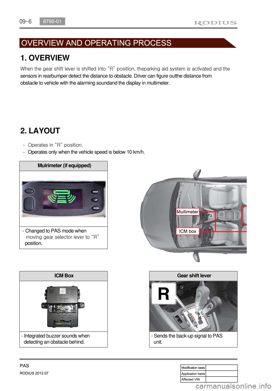
Gear shift lever
- Sends the back-up signal to PAS
unit.
1. OVERVIEW
<007e008f008c00950047009b008f008c0047008e008c008800990047009a008f0090008d009b00470093008c009d008c009900470090009a0047009a008f0090008d009b008c008b004700900095009b0096004702c8007902c9004700970096009a009000
9b00900096009500530047009b008f008c0097008800990092>ing aid system is activated and the
sensors in rearbumper detect the distance to obstacle. Driver can figure outthe distance from
obstacle to vehicle with the alarming soundand the display in multimeter.
2. LAYOUT
Operates in “R” position.
Operates only when the vehicle speed is below 10 km/h. -
-
Mulrimeter (if equipped)
- Changed to PAS mode when
moving gear selector lever to “R”
position.
ICM Box
- Integrated buzzer sounds when
detecting an obstacle behind.
Page 522 of 715

01-33650-01
Diameter( Torque converter) 270mm
Lockup function Yes
Gear ratios 1st 3.595
2nd 2.186
3rd 1.405
4th 1.000
5th 0.831
Reverse:
S mode / W mode3.167/1.926
Driving type 2WD(4WD)
Fluid specification Shell ATF 134
Fluid capacityapprox. 8ℓ
Selected lever
indicationP.R.N.D Mechanical
D+/D- Electrical
Parking lock systemBrake switch(signal) → TGS lever
Reverse lock systemCAN → TGS lever
Selected lever
indicationP.R.N.D Lever position
1, 2, 3, 4, 5 CAN
Oil temperature
sensorResistance: R, D0.5 ~ 2.5kΩ
Resistance: P, N20kΩ
TCU EGS 52
Shift solenoid
valve(25℃)Resistance3.8 ± 0.2Ω
Operating distance 0.2mm
Operating current 1.5 ~ 2A
Item W5A580(2WD) / W5A400(4WD)
Input torque 450Nm
1. SPECIFICATIONS
Page 523 of 715

01-4
항목W5A330(300) W5A580(400)
M/P, S/P solenoid
valve(23℃)Resistance5.0 ± 0.2Ω
Operating distance 0.6mm
Operating current 0 ~ 1A
Lockup solenoid
valve(25℃)Resistance2.5 ± 0.2Ω
Operating distance 0.2mm
Operating current 1.5 ~ 2.0A
Operating range 3rd to 5th gears
Speed sensor Resistance HALL type
Operating voltae 6V
Start lockout switch Switch contact ON(D position)
Switch contact OFF(P, N position)
Mode switch W(Winter)
S(Standard)
One-way clutch F1, F2
Planetary gear set Plain planetary gear:
3(number of pinion)3, 4, 3 4, 4, 4
Disc clutch Disc: C2*, C2, C3* Single plate type*
Disc brake Disc: B1*, B2, B3 Single plate type*
Item W5A580(2WD)/W5A400(4WD)
Page 526 of 715

01-73650-01
Part Name/Part Number Description
129 589 04 31 00
Straight edgeMeasure the distance between ball bearing shaft and
parking lock gear shaft
Compressor Compress the clutch/brake discs
Page 529 of 715

01-10
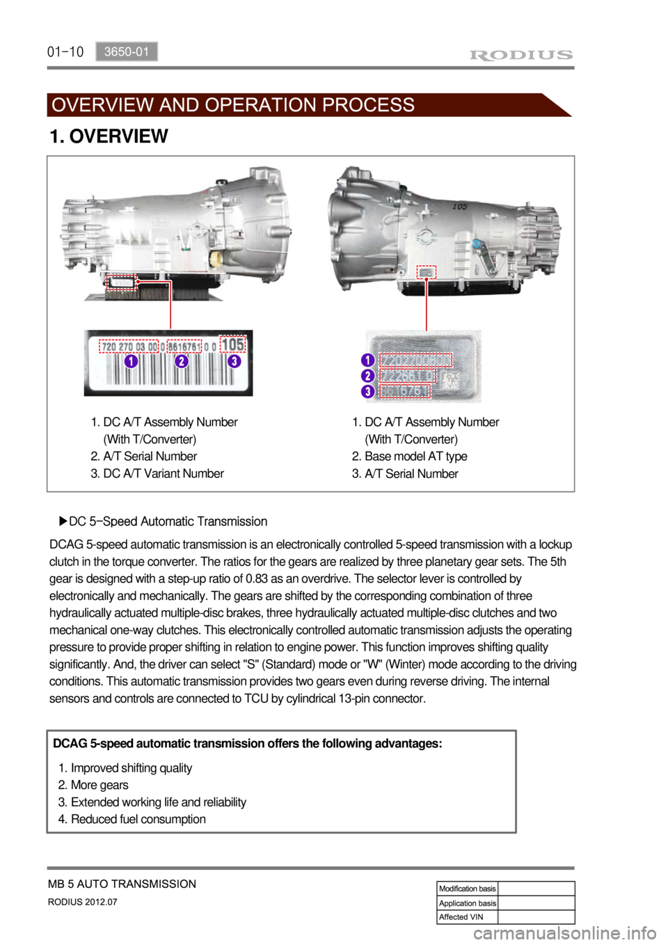
1. OVERVIEW
▶DC 5-Speed Automatic Transmission
DCAG 5-speed automatic transmission is an electronically controlled 5-speed transmission with a lockup
clutch in the torque converter. The ratios for the gears are realized by three planetary gear sets. The 5th
gear is designed with a step-up ratio of 0.83 as an overdrive. The selector lever is controlled by
electronically and mechanically. The gears are shifted by the corresponding combination of three
hydraulically actuated multiple-disc brakes, three hydraulically actuated multiple-disc clutches and two
mechanical one-way clutches. This electronically controlled automatic transmission adjusts the operating
pressure to provide proper shifting in relation to engine power. This function improves shifting quality
significantly. And, the driver can select "S" (Standard) mode or "W" (Winter) mode according to the driving
conditions. This automatic transmission provides two gears even during reverse driving. The internal
sensors and controls are connected to TCU by cylindrical 13-pin connector.
DCAG 5-speed automatic transmission offers the following advantages:
Improved shifting quality
More gears
Extended working life and reliability
Reduced fuel consumption 1.
2.
3.
4.
DC A/T Assembly Number
(With T/Converter)
A/T Serial Number
DC A/T Variant Number 1.
2.
3.DC A/T Assembly Number
(With T/Converter)
Base model AT type
A/T Serial Number 1.
2.
3.