Gear SSANGYONG RODIUS 2012 User Guide
[x] Cancel search | Manufacturer: SSANGYONG, Model Year: 2012, Model line: RODIUS, Model: SSANGYONG RODIUS 2012Pages: 715, PDF Size: 79.36 MB
Page 194 of 715

02-370000-00
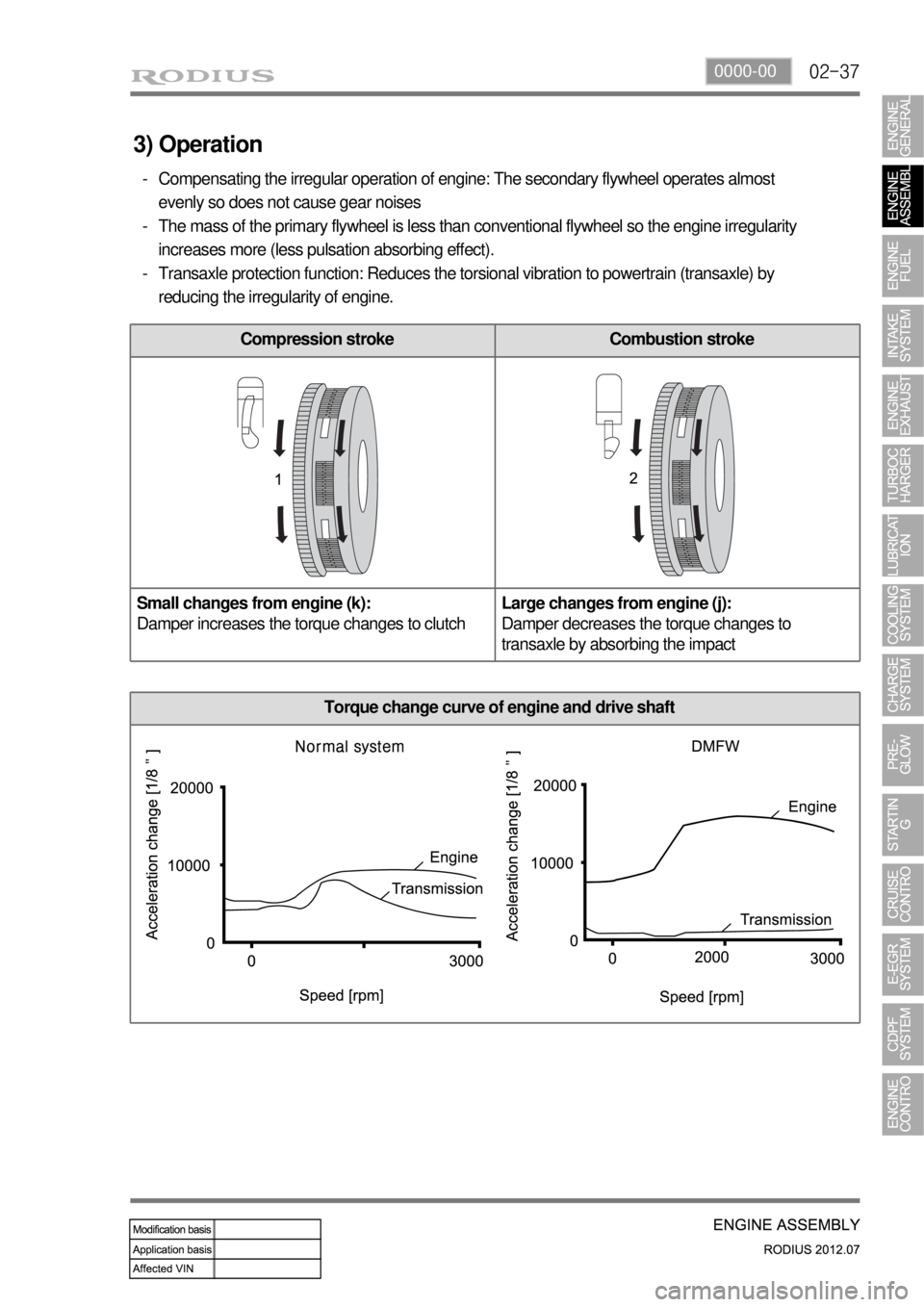
Torque change curve of engine and drive shaft
Compression stroke Combustion stroke
Small changes from engine (k):
Damper increases the torque changes to clutchLarge changes from engine (j):
Damper decreases the torque changes to
transaxle by absorbing the impact
3) Operation
Compensating the irregular operation of engine: The secondary flywheel operates almost
evenly so does not cause gear noises
The mass of the primary flywheel is less than conventional flywheel so the engine irregularity
increases more (less pulsation absorbing effect).
Transaxle protection function: Reduces the torsional vibration to powertrain (transaxle) by
reducing the irregularity of engine. -
-
-
Page 195 of 715

02-38
4) Features
Reduced vibration noise from the powertrain by blocking the torsional vibrations
Enhanced vehicle silence and riding comforts: reduced engine torque fluctuation
Reduced shifting shocks
Smooth acceleration and deceleration -
-
-
-
5) Advantages
Improved torque response by using 3-stage type spring: Strengthens the torque response in all
ranges (low, medium, and high speed) by applying respective spring constant at each range.
Stable revolution of the primary and secondary wheel by using planetary gear: Works as
auxiliary damper against spring changes
Less heat generation due to no direct friction against spring surface: Plastic material is covered
on the spring outer surface
Increased durability by using plastic bushing (extends the lifetime of grease) -
-
-
-
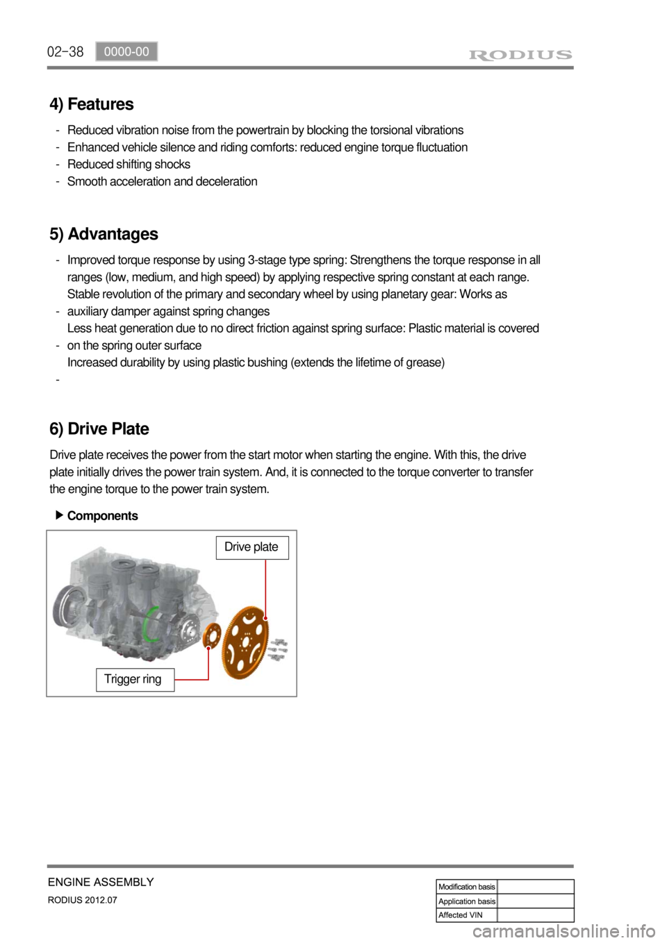
6) Drive Plate
Drive plate receives the power from the start motor when starting the engine. With this, the drive
plate initially drives the power train system. And, it is connected to the torque converter to transfer
the engine torque to the power train system.
Trigger ring
Drive plate
Components ▶
Page 207 of 715

03-32210-01
1. SPECIFICATIONS
Description Specification
Fuel Diesel
Fuel filter Type Fuel heater + priming pump + water
separator integrated type
Filter type Changeable filter element type
Change interval EU every 40,000 km
GEN every 45,000 km
Water separation
intervalEU every 20,000 km
GEN every 15,000 km
Water accumulating capacity 200 cc
Heater capacity 250W 13.5V
Injector System pressure 1800 bar
High pressure fuel
pumpType Eccentric cam/Plunger type
Operating type Gear driven type
Normal operating temperature-40 ~ 125˚C
Operating pressure 1800 bar
Operating temperature-30 ~ 120˚C
Low pressure fuel
pumpType Vane type
Gear ratio (pump/engine) 0.5 : 1
Pressure 6 bar
Fuel tank Capacity 80 L
Material Steel
Fuel sender Single sender type
Page 228 of 715

03-24
2) Fuel System Flow Diagram
The fuel from the fuel tank is supplied to the fuel heater of fuel filter/priming pump and then low
pressure generated by the low pressure pump (built into HP pump) is transmitted to the HP pump.
The fuel pressure at the HP pump is controlled by the IMV valve, and the maximum allowed
pressure is 1,800 bar. The compressed fuel at the fuel pump is delivered to the rail, and injected
by the injectors according to the injection signals. The injection method is the same with the
conventional method; Fuel return by backleak which operates the needle valve.
The major difference is that the fuel return line is connected to the fuel filter inlet port, not the HP
pump venturi.
The pressure from the high pressure pump is increased to 1,800 bar from 1,600 bar, and the
pump is now installed to the cylinder head (cylinder block for previous model). The fuel pressure
is generated by the operation of intake camshaft and gears. The specifications for the IMV valve
and the fuel temperature sensor are not changed.
Page 247 of 715

06-6
3) Inspection of Turbine
Thoroughly check the followings.
Must absolutely not operate the turbocharger with the compressor outlet and inlet opened as it
could damage the turbocharger or be hazardous during inspection.
Interference: In case where is trace of interference or smallest damage on the compressor
wheel means, most of times, that abrasion has occurred on the journal bearing. Must inspect
after the overhaul.
Oil Leakage: The reason for oil leakage at the compressor section is the air cleaner, clogged
by substances such as dust, causes the compressor inlet negative pressure. -
-
Rotating in high speed at no-load for extended period of time can cause oil leakage to the
compressor section as oil pressure within the center housing gets higher than pressure
within the compressor housing.
Overuse of engine break (especially in low gear) in down hill makes significantly low
exhaust gas energy compared to the time where great amount of air is required during
idling conditions of the engine. Therefore, amount of air in the compressor inlet increases
but the turbocharge pressure is not high, which makes negative a.
b.
No problem will occur with the turbocharger if above conditions are found in early stage but oil
leaked over long period of time will solidify at each section causing to breakout secondary
defects.
Damages by foreign materials: In case where the compressor wheel is damaged by foreign
materials requires having an overhaul. At this time, it's necessary to check whether the foreign
materials have contaminated intake/exhaust manifold or inside of engine.
Page 264 of 715

07-31543-00
1. SPECIFICATION
The engine oil filter element should be changed at the same time with the engine oil.
Regularly check the engine oil level and add the engine oil if necessary.
Remember to check the engine oil level and shorten the cycle to replace the engine oil
under severe driving conditions. -
-
Severe Driving Condition
Frequent stop-and-go traffic, extended idling, short driving distance below 6 km, driving
distance below 16 km when the outside temperature remains below freezing
Driving in a hilly or mountainous terrain, sandy, or dusty area
High load driving such as trailer towing
Taxi, patrol service or delivery service (extended idling and excessive driving with low speed) -
-
-
-
Unit Specification
Oil pump Lubrication system Gear pump, forced circulation
Type Inscribed gear
Capacity 63 L at 4,000 rpm
Relief pressure5.8 bar ± 0.3 bar
Oil filter Type Full flow/Paper element
Engine oil Specified oil SAE 5W30 (approved by MB SHEET 229.51)
Capacity (L) Min.: 4.5 L
Max.: 6.0 L
Service
intervalEU Change every 20,000 km or 12 months
(The service interval should be shortened under
severe conditions)
General Change every 15,000 km or 12 months
(The service interval should be shortened under
severe conditions)
Oil injection nozzle Type Piston
Operating pressure 1.5bar
Closing pressure 1.0bar
Oil flow 4 L/min
Oil pressure switch Permissible pressure 10bar
Page 276 of 715

09-4
2. INSPECTION
1) Alternator Output Test
Item How to check DTC set value / Action
Output
current
B terminal
current
Rotor
coil
resistance
D terminal
voltage
Disconnect the cable connected to the
B terminal on the alternator. Connect
one end of the ammeter to the B
terminal and the other end to the cable
connected to the B terminal.
Measure the maximum output value.
(Maintain the engine speed between
2,500 and 3,000 rpm.)
(Turn the headlamp and all the electrical
switches on.) 1.
2.Pass: If the measured current is
45 A or higher.
Fail: If the measured current is
less than 45 A.
Check the current of the B
terminal. -
-
-
Move the gear selector lever to the
neutral position.
Maintain the engine speed at 2,500 rpm
with the vehicle unloaded.
(Turn all the electrical switches off.) 1.
2.Open circuit: If the measured
current is 5 A or higher. -
Disconnect the negative cable from the
battery.
Remove the B terminal and turn off the
ignition switch.
Measure the resistance between the L
and F terminals with an ohmmeter. 1.
2.
3.Pass: If the measured resistance
is between 3 and 6 Ω.
Faulty rotor coil or slip ring: If the
measured resistance is less than
3 Ω or greater than 6 Ω. -
-
Connect the B terminal wiring.
Measure the voltage with the engine
running. 1.
2.Specification: 12.5 V to 14.5 V
Faulty IC regulator or field coil: If
the measured voltage is 14.5 V
or higher. -
-
Disconnect the negative battery cable.
Connect the negative cable again after connecting the ammeter. -
-
Page 294 of 715

11-31461-01
1. SPECIFICATION
Description Specification
Capacity 12V 2.3kW
Engagement Meshed type
Rotating direction Clockwise
Pinion gear manufacturing Cooled forging
Solenoid operating voltage Max. 8 V
Weight 2.5 kg
Bracket manufacturing Aluminum die casting
Page 295 of 715

11-4
2. TROUBLESHOOTING
Problem Possible Cause Action
Engine will not crankLow battery voltage Charge or replace
Loose, corroded or damaged battery cable
Repair or replace
Faulty starter or open circuit
Faulty ignition switch or blown fuseRepair or replace
Poor engine ground Repair
Engine cranks too
slowLow battery voltage Charge or replac
Loose, corroded or damaged battery cable
Repair or replace Faulty starter
Starter does not
stopFaulty starter
Faulty ignition switch Replace
Engine cranks
normally, but does
not startBroken pinion gear or faulty starter
Replace the starter
Broken flywheel ring gear Replace
Open circuit Repair
Page 296 of 715

11-51461-01
1. SYSTEM DESCRIPTION
The starter (start motor) starts the engine with rotational power by converting the electric energy to
the mechanical energy.
When the engine is cranking, the pinion gear meshes with the ring gear. If the ring gear overruns,
the pinion gear clutch overruns to protect the pinion gear.
2. OPERATING PROCESS
1) System Layout