Gear SSANGYONG RODIUS 2012 Workshop Manual
[x] Cancel search | Manufacturer: SSANGYONG, Model Year: 2012, Model line: RODIUS, Model: SSANGYONG RODIUS 2012Pages: 715, PDF Size: 79.36 MB
Page 573 of 715

05-6
Operation ▶
Description Mode Conditions
Driving mode 2H 2 Wheel drive
(rear wheel)Rear-wheel drive mode. This is used under
normal or high-speed driving conditions on public
roads or highways.
4H 4 Wheel drive
(high speed)This is used under sandy, muddy or snow-
covered road conditions
4L 4 Wheel drive
(low speed)This is used for maximum traction.
When cornering with low speed in 4WD condition,
there could be tire dragging, some
mechanical shocks and resistances in vehicle’s
drive train. These are normal conditions due to
internal resistance in the drive train when the
4WD system is properly working
Mode change2H ↔
4H 2 Wheel drive
↔4 Wheel driveShifting is possible while driving at the speed of
70 km/h or less
2H, 4H
↔ 4L 2 Wheel drive,
4 Wheel drive
(high speed)
↔4 Wheel drive
(low speed)
To make the mode change easily, stop the
vehicle on level ground and turn the mode
switch to the desired position and move the
shift lever to "N"-"R"-"N" while depressing
the brake pedal. For Automatic Transmission:
Stop the vehicle on level ground and move
the gear selector lever into the “N” position.
Turn the switch to the desired position. -
For Manual Transmission:
Stop the vehicle on level ground and move
the gear selector lever into the “N” position.
Then turn the switch to the desired position
while depressing the clutch pedal. -
Page 576 of 715

05-93240-01
4. IWE LOCKING HUB SYSTEM
1) Overview
The vacuum locking hub uses the IWE (Integrated Wheel End) system, and in this system, the
vacuum is generated only within the hub actuator.
It is structured to transmit power to the front section after the actuator hub is engaged following
the release of vacuum from the drive shaft end gear and the hub end gear
Booster
Operating Process
Vacuum pump
Vacuum generation process in front hub actuator ▶
Page 577 of 715

05-10
(2) Vacuum System Related to 4WD
In 4WD mode, the TCCU blocks the
transferring of vacuum pressure from
vacuum pump to locking hub by supplying
the power to solenoid valve.Check valve
This valve allows the vacuum pressure to
flow through it in only one direction. This
prevent the vacuum from abruptly
releasing due to faulty vacuum pump.
4WD:
The vacuum pressure is released from the
hub actuator. At this time, the front hub end
gear is engaged.2WD:
The vacuum pressure pulls in the locking
hub actuator so that it will not be engaged
with the front end hub gear.
Vacuum solenoid valve
To atmosphere Block the vacuum
pressure
Hub actuator (RH)
Gear disengagedGear engaged
Page 581 of 715

05-14
3) 4L Mode (4 Wheel Drive - Low Speed)
Power Flow ▶
The gear ratio is reduced to 2.48;1 while passing through 4WD Low range and planetary gear
set in transfer case and the driving force is distributed on front wheels and rear wheels
(50;50).
Page 584 of 715

06-53310-01
1. OVERVIEW
The propeller shaft transfers the power through the transmission and transfer case to the
front/rear axle differential carrier (final reduction gear). It is manufactured by a thin rounded steel
pipe to have the strong resisting force against the torsion and bending. Both ends of propeller
shaft are connected to the spider and the center of propeller shaft is connected to the spline to
accommodate the changes of the height and length. The rubber bushing that covers the
intermediate bearing keeps the balance of rear propeller shaft and absorbs its vibration.
Function of propeller shaft ▶
Transmits driving torque.
Compensates the angle change (universal joint / CV joint).
Compensates the axial length change (splines for the slip joint). -
-
-
4WD AT 2WD MT
Page 641 of 715

11-34610-00
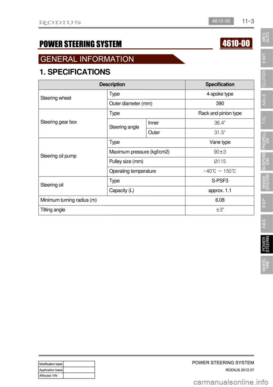
1. SPECIFICATIONS
Description Specification
Steering wheelType 4-spoke type
Outer diameter (mm) 390
Steering gear boxType Rack and pinion type
Steering angleInner36.4°
Outer31.5°
Steering oil pumpType Vane type
Maximum pressure (kgf/cm2)90±3
Pulley size (mm)Ø115
Operating temperature-40℃ ~ 150℃
Steering oilType S-PSF3
Capacity (L) approx. 1.1
Minimum turning radius (m) 6.08
Tilting angle±3°
Page 642 of 715

11-4
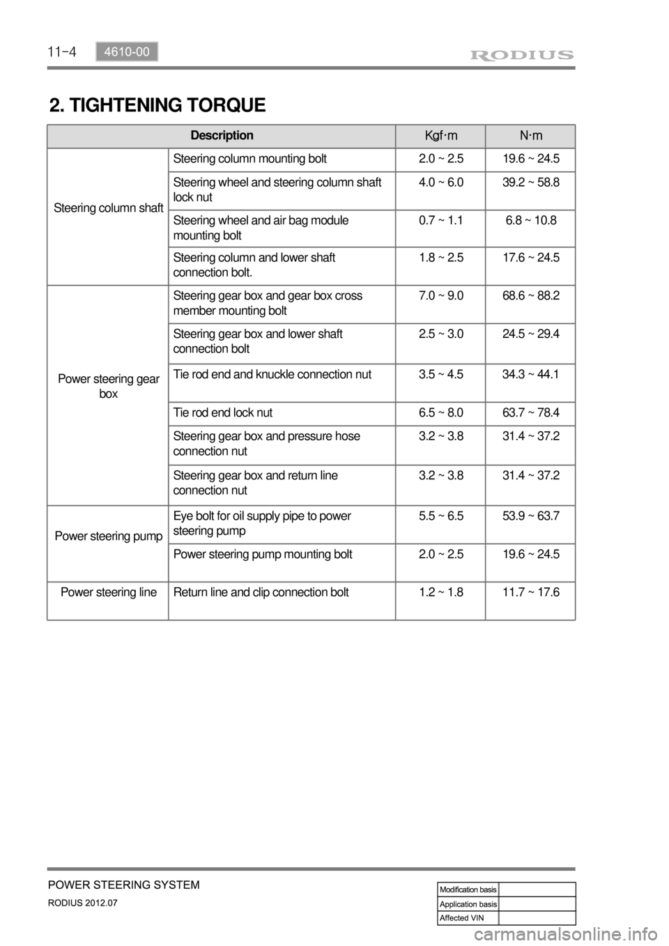
2. TIGHTENING TORQUE
DescriptionKgf·m N·m
Steering column shaftSteering column mounting bolt 2.0 ~ 2.5 19.6 ~ 24.5
Steering wheel and steering column shaft
lock nut4.0 ~ 6.0 39.2 ~ 58.8
Steering wheel and air bag module
mounting bolt0.7 ~ 1.1 6.8 ~ 10.8
Steering column and lower shaft
connection bolt.1.8 ~ 2.5 17.6 ~ 24.5
Power steering gear
boxSteering gear box and gear box cross
member mounting bolt7.0 ~ 9.0 68.6 ~ 88.2
Steering gear box and lower shaft
connection bolt2.5 ~ 3.0 24.5 ~ 29.4
Tie rod end and knuckle connection nut 3.5 ~ 4.5 34.3 ~ 44.1
Tie rod end lock nut 6.5 ~ 8.0 63.7 ~ 78.4
Steering gear box and pressure hose
connection nut3.2 ~ 3.8 31.4 ~ 37.2
Steering gear box and return line
connection nut3.2 ~ 3.8 31.4 ~ 37.2
Power steering pumpEye bolt for oil supply pipe to power
steering pump5.5 ~ 6.5 53.9 ~ 63.7
Power steering pump mounting bolt 2.0 ~ 2.5 19.6 ~ 24.5
Power steering line Return line and clip connection bolt 1.2 ~ 1.8 11.7 ~ 17.6
Page 643 of 715

11-54610-00
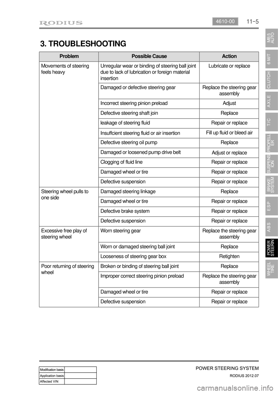
3. TROUBLESHOOTING
Problem Possible Cause Action
Movements of steering
feels heavyUnregular wear or binding of steering ball joint
due to lack of lubrication or foreign material
insertionLubricate or replace
Damaged or defective steering gear Replace the steering gear
assembly
Incorrect steering pinion preload Adjust
Defective steering shaft join Replace
leakage of steering fluid Repair or replace
Insuffcient steering fluid or air insertionFill up fluid or bleed air
Defective steering oil pump Replace
Damaged or loosened pump drive belt
Adjust or replace
Clogging of fluid line Repair or replace
Damaged wheel or tire Repair or replace
Defective suspension Repair or replace
Steering wheel pulls to
one sideDamaged steering linkage Replace
Damaged wheel or tire Repair or replace
Defective brake system Repair or replace
Defective suspension Repair or replace
Excessive free play of
steering wheelWorn steering gear Replace the steering gear
assembly
Worn or damaged steering ball joint Replace
Looseness of steering gear box Retighten
Poor returning of steering
wheelBroken or binding of steering ball joint Replace
Improper correct steering pinion preload Replace the steering gear
assembly
Damaged wheel or tire Repair or replace
Defective suspension Repair or replace
Page 644 of 715

11-6
Problem Possible Cause Action
Excessive vibration of
steering wheel (shimming)Broken steering linkage Replace
Looseness of steering gear box Retighten
Broken or binding of steering ball joint Replace
Worn or damaged front wheel bearing Replace
Damaged wheel or tire Repair or replace
Defective suspension Repair or replace
Abnormal noise from
steering systemLooseness of steering gear box Retighten
Defective steering gear Replace the gear
assembly
Interference between steering column and
partsRepair
Looseness of steering linkage Retighten
Loosened or damaged oil pump drive belt Repair or replace
Looseness of oil pump bracket Retighten
Looseness of oil pump Retighten
Air insertion into system Bleed air
Defective oil pump Replace
Abnormal noise when
turning steering wheelLooseness of steering column Retighten
Worn or damaged steering shaft bearing Replace the steering
column
Looseness of intermediate shaft Retighten
Too heavy steering wheel Worn or damaged steering shaft bearing Replace the steering
column
Ignition key cannot be
inserted into key cylinderDefective lock cylinder Replace the steering
column
Defective ignition switch Replace the ignition switch