brake SSANGYONG RODIUS 2012 Owner's Manual
[x] Cancel search | Manufacturer: SSANGYONG, Model Year: 2012, Model line: RODIUS, Model: SSANGYONG RODIUS 2012Pages: 715, PDF Size: 79.36 MB
Page 473 of 715

02-42
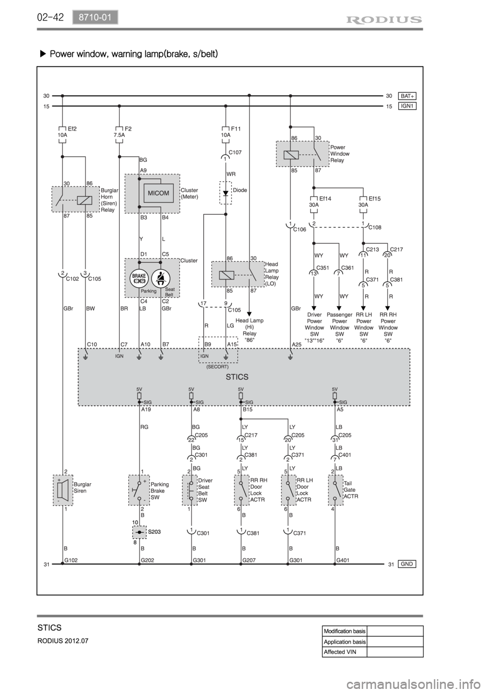
▶ Power window, warning lamp(brake, s/belt)
Page 522 of 715

01-33650-01
Diameter( Torque converter) 270mm
Lockup function Yes
Gear ratios 1st 3.595
2nd 2.186
3rd 1.405
4th 1.000
5th 0.831
Reverse:
S mode / W mode3.167/1.926
Driving type 2WD(4WD)
Fluid specification Shell ATF 134
Fluid capacityapprox. 8ℓ
Selected lever
indicationP.R.N.D Mechanical
D+/D- Electrical
Parking lock systemBrake switch(signal) → TGS lever
Reverse lock systemCAN → TGS lever
Selected lever
indicationP.R.N.D Lever position
1, 2, 3, 4, 5 CAN
Oil temperature
sensorResistance: R, D0.5 ~ 2.5kΩ
Resistance: P, N20kΩ
TCU EGS 52
Shift solenoid
valve(25℃)Resistance3.8 ± 0.2Ω
Operating distance 0.2mm
Operating current 1.5 ~ 2A
Item W5A580(2WD) / W5A400(4WD)
Input torque 450Nm
1. SPECIFICATIONS
Page 523 of 715

01-4
항목W5A330(300) W5A580(400)
M/P, S/P solenoid
valve(23℃)Resistance5.0 ± 0.2Ω
Operating distance 0.6mm
Operating current 0 ~ 1A
Lockup solenoid
valve(25℃)Resistance2.5 ± 0.2Ω
Operating distance 0.2mm
Operating current 1.5 ~ 2.0A
Operating range 3rd to 5th gears
Speed sensor Resistance HALL type
Operating voltae 6V
Start lockout switch Switch contact ON(D position)
Switch contact OFF(P, N position)
Mode switch W(Winter)
S(Standard)
One-way clutch F1, F2
Planetary gear set Plain planetary gear:
3(number of pinion)3, 4, 3 4, 4, 4
Disc clutch Disc: C2*, C2, C3* Single plate type*
Disc brake Disc: B1*, B2, B3 Single plate type*
Item W5A580(2WD)/W5A400(4WD)
Page 526 of 715

01-73650-01
Part Name/Part Number Description
129 589 04 31 00
Straight edgeMeasure the distance between ball bearing shaft and
parking lock gear shaft
Compressor Compress the clutch/brake discs
Page 529 of 715

01-10
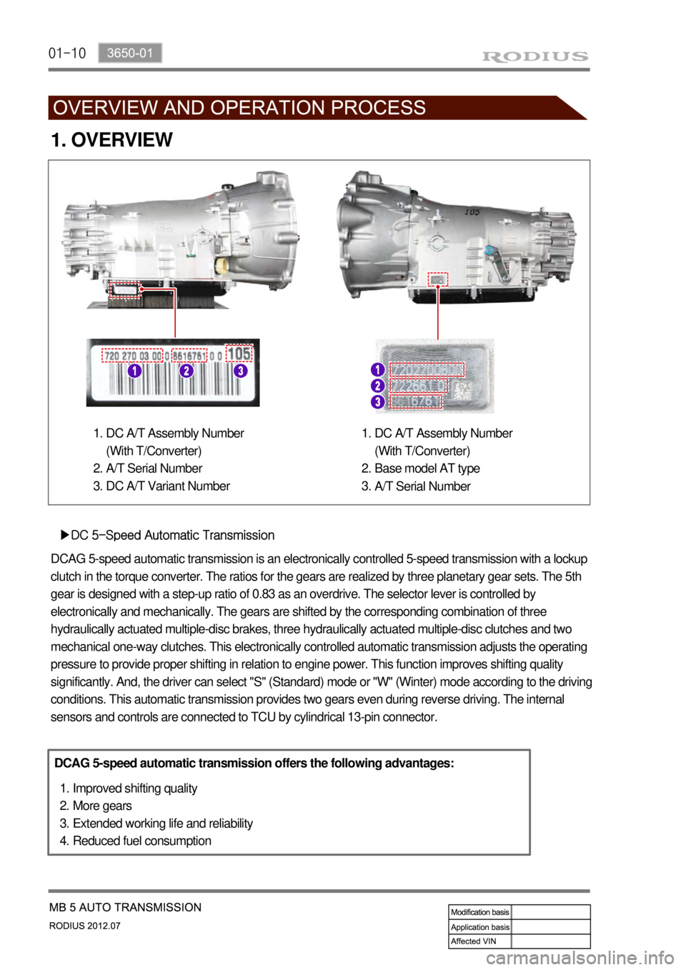
1. OVERVIEW
▶DC 5-Speed Automatic Transmission
DCAG 5-speed automatic transmission is an electronically controlled 5-speed transmission with a lockup
clutch in the torque converter. The ratios for the gears are realized by three planetary gear sets. The 5th
gear is designed with a step-up ratio of 0.83 as an overdrive. The selector lever is controlled by
electronically and mechanically. The gears are shifted by the corresponding combination of three
hydraulically actuated multiple-disc brakes, three hydraulically actuated multiple-disc clutches and two
mechanical one-way clutches. This electronically controlled automatic transmission adjusts the operating
pressure to provide proper shifting in relation to engine power. This function improves shifting quality
significantly. And, the driver can select "S" (Standard) mode or "W" (Winter) mode according to the driving
conditions. This automatic transmission provides two gears even during reverse driving. The internal
sensors and controls are connected to TCU by cylindrical 13-pin connector.
DCAG 5-speed automatic transmission offers the following advantages:
Improved shifting quality
More gears
Extended working life and reliability
Reduced fuel consumption 1.
2.
3.
4.
DC A/T Assembly Number
(With T/Converter)
A/T Serial Number
DC A/T Variant Number 1.
2.
3.DC A/T Assembly Number
(With T/Converter)
Base model AT type
A/T Serial Number 1.
2.
3.
Page 538 of 715

01-193650-01
▶Reverse 2nd Gear (1.926)
Torque converter lockup clutch
Engine speed
Transmission, input shaft
1st gear ratio 16.
A.
B.
C.2nd gear ratio
Mounting elements
Rear planetary gear set
Stator D.
E.
H.
L.Center planetary gear set
Impeller
Turbine wheel
Front planetary gear set M.
P.
T.
V.
Input shaft: Clockwise rotation
Front ring gear: Clockwise rotation
Front planetary gear carrier: Clockwise rotation by clutch C1 activation (direct connection)
Rear ring gear: Clockwise rotation
Rear planetary gear carrier and center ring gear: Locked by brake B3
Rear sun gear and center sun gear: Counterclockwise rotation (increased speed)
Center planetary gear carrier: Counterclockwise rotation (reduced speed)
Output shaft: Counterclockwise rotation -
-
-
-
-
-
-
-
Gear C1 C2 C3 B1 B2 B3 F1 F2
R (W) ● ● ●
Page 573 of 715

05-6
Operation ▶
Description Mode Conditions
Driving mode 2H 2 Wheel drive
(rear wheel)Rear-wheel drive mode. This is used under
normal or high-speed driving conditions on public
roads or highways.
4H 4 Wheel drive
(high speed)This is used under sandy, muddy or snow-
covered road conditions
4L 4 Wheel drive
(low speed)This is used for maximum traction.
When cornering with low speed in 4WD condition,
there could be tire dragging, some
mechanical shocks and resistances in vehicle’s
drive train. These are normal conditions due to
internal resistance in the drive train when the
4WD system is properly working
Mode change2H ↔
4H 2 Wheel drive
↔4 Wheel driveShifting is possible while driving at the speed of
70 km/h or less
2H, 4H
↔ 4L 2 Wheel drive,
4 Wheel drive
(high speed)
↔4 Wheel drive
(low speed)
To make the mode change easily, stop the
vehicle on level ground and turn the mode
switch to the desired position and move the
shift lever to "N"-"R"-"N" while depressing
the brake pedal. For Automatic Transmission:
Stop the vehicle on level ground and move
the gear selector lever into the “N” position.
Turn the switch to the desired position. -
For Manual Transmission:
Stop the vehicle on level ground and move
the gear selector lever into the “N” position.
Then turn the switch to the desired position
while depressing the clutch pedal. -
Page 594 of 715

08-34850-03
Brake oil Grade DOT 4
Service interval Replace every 2 years
1. SPECIFICATIONS
Description Specification
Front brake Type Ventilated disc
Rear brake Type Ventilated disc
Master cylinder Type Step feed bore tandem, double cylinder
Brake booster Type Tandem type(integrated level sensor)
Operating type Foot operated type
Page 596 of 715

08-54850-03
3. TROUBLESHOOTING
Problem Possible Cause Action
Noise or vehicle
vibration when
appliedIncorrectly mounted back plate or caliper Repair
Loosened bolt of back plate or caliper Retighten
Uneven wear of brake disc Replace
Brake pad contamination Clean or replace
Sticking brake pad on contact surface Replace
Wear or hardening of brake pad Replace
Excessive clearance between caliper and pad Repair
Uneven contact of pad Repair
Lack of lubrication in sliding parts Lubricate
Improper operation of caliper Replace
Dust cover missing Repair
Loosened suspension mounting bolt Retighten
Pulls to one side
when brakingUnbalanced tire pressure between left and right Adjust
Poor contact of brake pad Repair
Oil or grease on brake pad Replace
Scratch, uneven wear, distortion of brake disc Replace
Improperly installed brake caliper Repair
Improper operation of auto adjuster Repair
Crack or distortion of brake pad Replace
Poor braking Oil leak or contamination Repair or replace
Air in brake line Bleed air
Improper operation of brake booster Repair
Poor contact of brake pad Repair
Oil or grease on brake pad Replace
Improper operation of auto adjuster Repair
Clogged brake line Repair
Improper operation of proportioning valve Repair
Page 597 of 715

08-6
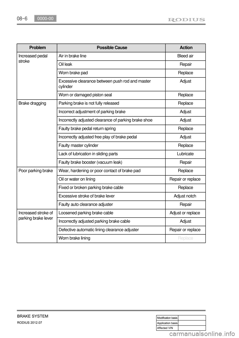
Problem Possible Cause Action
Increased pedal
strokeAir in brake line Bleed air
Oil leak Repair
Worn brake pad Replace
Excessive clearance between push rod and master
cylinderAdjust
Worn or damaged piston seal Replace
Brake dragging Parking brake is not fully released Replace
Incorrect adjustment of parking brake Adjust
Incorrectly adjusted clearance of parking brake shoe Adjust
Faulty brake pedal return spring Replace
Incorrectly adjusted free play of brake pedal Adjust
Faulty master cylinder Replace
Lack of lubrication in sliding parts Lubricate
Faulty brake booster (vacuum leak) Repair
Poor parking brake Wear, hardening or poor contact of brake pad Replace
Oil or water on lining Repair or replace
Fixed or broken parking brake cable Replace
Excessive stroke of brake lever Adjust notch
Faulty auto clearance adjuster Repair
Increased stroke of
parking brake leverLoosened parking brake cable Adjust or replace
Incorrectly adjusted parking brake cable Adjust
Defective automatic lining clearance adjuster Repair or replace
Worn brake liningReplace