oil SSANGYONG RODIUS 2012 Workshop Manual
[x] Cancel search | Manufacturer: SSANGYONG, Model Year: 2012, Model line: RODIUS, Model: SSANGYONG RODIUS 2012Pages: 715, PDF Size: 79.36 MB
Page 326 of 715

14-16
7. CAUTIONS
1) Designated Engine Oil for CDPF (Low Ash Oil)
Need to use the designated engine oil for CDPF 1.
The smoke from the vehicle may generate the particle material in the ambient air. CDPF is
the device to reduce the smoke by collecting and recycling it. To ensure the performance
of CDPF, the designated engine oil should be used.
The smoke including combusted sulfur in fuel cannot be recycled in CDPF. This smoke
generates the ash, resulting in clogging the filter. -
-
Advantages when using the designated engine oil for CDPF 2.
Reduces the amount of ash
Improves the fuel economy and reduces the CO2
Increases the life span of engine oil
Available for all engines (diesel and gasoline) -
-
-
-
Problems when using non-designated engine oil for CDPF 3.
Decreases the life span of engine oil due to accumulated ash in DPF (around 30%)
Decreases the fuel economy due to friction resistance, exhaust gas resistance and
frequent recycling process of DPF -
-
The fuel containing high sulfur may cause the same problems.
Page 336 of 715
15-110000-00
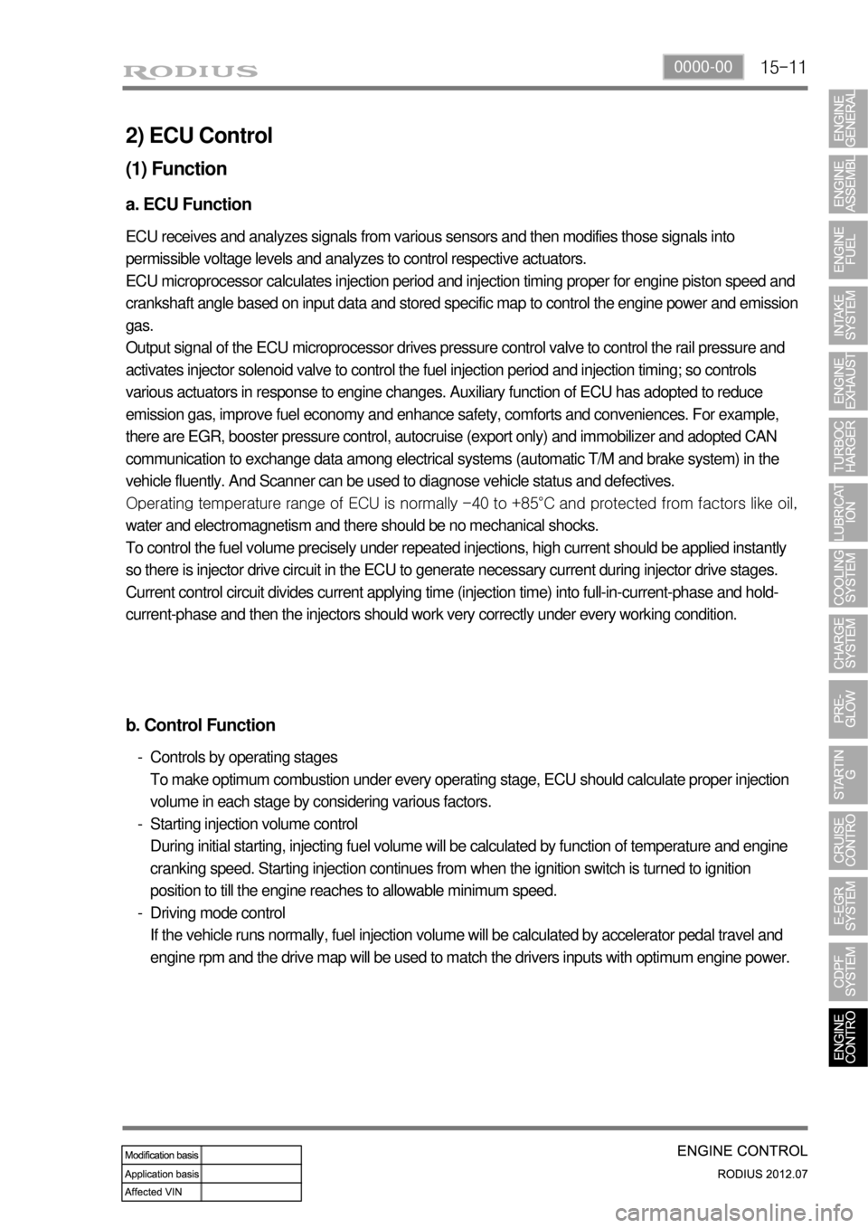
2) ECU Control
(1) Function
a. ECU Function
ECU receives and analyzes signals from various sensors and then modifies those signals into
permissible voltage levels and analyzes to control respective actuators.
ECU microprocessor calculates injection period and injection timing proper for engine piston speed and
crankshaft angle based on input data and stored specific map to control the engine power and emission
gas.
Output signal of the ECU microprocessor drives pressure control valve to control the rail pressure and
activates injector solenoid valve to control the fuel injection period and injection timing; so controls
various actuators in response to engine changes. Auxiliary function of ECU has adopted to reduce
emission gas, improve fuel economy and enhance safety, comforts and conveniences. For example,
there are EGR, booster pressure control, autocruise (export only) and immobilizer and adopted CAN
communication to exchange data among electrical systems (automatic T/M and brake system) in the
vehicle fluently. And Scanner can be used to diagnose vehicle status and defectives.
<00760097008c00990088009b00900095008e0047009b008c00940097008c00990088009b009c0099008c0047009900880095008e008c00470096008d0047006c006a007c00470090009a0047009500960099009400880093009300a000470054005b005700
47009b009600470052005f005c00b6006a004700880095008b> protected from factors like oil,
water and electromagnetism and there should be no mechanical shocks.
To control the fuel volume precisely under repeated injections, high current should be applied instantly
so there is injector drive circuit in the ECU to generate necessary current during injector drive stages.
Current control circuit divides current applying time (injection time) into full-in-current-phase and hold-
current-phase and then the injectors should work very correctly under every working condition.
b. Control Function
Controls by operating stages
To make optimum combustion under every operating stage, ECU should calculate proper injection
volume in each stage by considering various factors.
Starting injection volume control
During initial starting, injecting fuel volume will be calculated by function of temperature and engine
cranking speed. Starting injection continues from when the ignition switch is turned to ignition
position to till the engine reaches to allowable minimum speed.
Driving mode control
If the vehicle runs normally, fuel injection volume will be calculated by accelerator pedal travel and
engine rpm and the drive map will be used to match the drivers inputs with optimum engine power. -
-
-
Page 363 of 715
15-38
Relay box
A/C
compressorHFM (intake air
temperature)Cooling fan
module
MB 5 A/T (ATF
temperature)Coolant
temperature
sensor
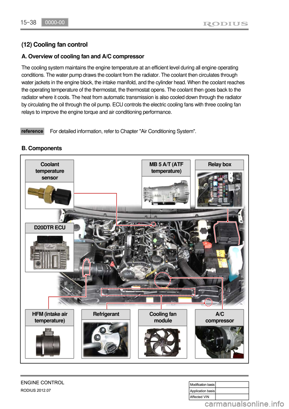
(12) Cooling fan control
A. Overview of cooling fan and A/C compressor
The cooling system maintains the engine temperature at an efficient level during all engine operating
conditions. The water pump draws the coolant from the radiator. The coolant then circulates through
water jackets in the engine block, the intake manifold, and the cylinder head. When the coolant reaches
the operating temperature of the thermostat, the thermostat opens. The coolant then goes back to the
radiator where it cools. The heat from automatic transmission is also cooled down through the radiator
by circulating the oil through the oil pump. ECU controls the electric cooling fans with three cooling fan
relays to improve the engine torque and air conditioning performance.
For detailed information, refer to Chapter "Air Conditioning System".
B. Components
D20DTR ECU
Refrigerant
Page 365 of 715
15-40
D. Cooling fan and A/C compressor control
Conditions for cooling fan control ▶
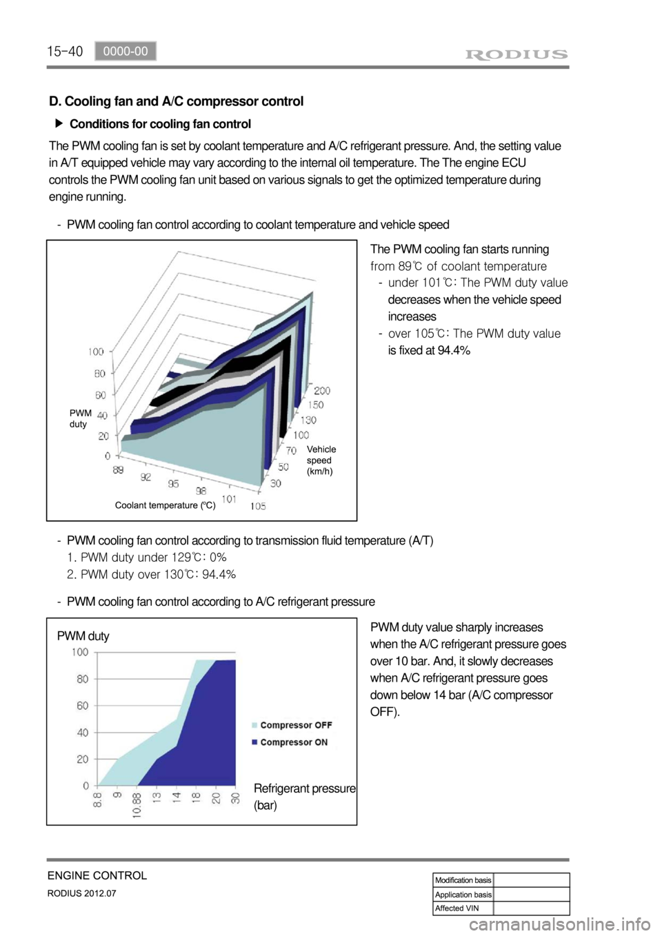
The PWM cooling fan is set by coolant temperature and A/C refrigerant pressure. And, the setting value
in A/T equipped vehicle may vary according to the internal oil temperature. The The engine ECU
controls the PWM cooling fan unit based on various signals to get the optimized temperature during
engine running.
PWM cooling fan control according to coolant temperature and vehicle speed -
The PWM cooling fan starts running
from 89℃ of coolant temperature
PWM cooling fan control according to transmission fluid temperature (A/T)
1. PWM duty under 129℃: 0%
2. PWM duty over 130℃: 94.4% -
PWM cooling fan control according to A/C refrigerant pressure -
PWM duty value sharply increases
when the A/C refrigerant pressure goes
over 10 bar. And, it slowly decreases
when A/C refrigerant pressure goes
down below 14 bar (A/C compressor
OFF). PWM duty
Refrigerant pressure
(bar)under 101℃: The PWM duty value
decreases when the vehicle speed
increases
over 105℃: The PWM duty value
is fixed at 94.4% -
-
Page 374 of 715

15-490000-00
E. Cautions
Use only specified Engine Oil (approved by MB Sheet 229.51) for CDPF. -
Use only specified engine oil (Low Ash Oil) ▶
The vehicle equipped with CDPF should use specific engine oil to improve the engine performance
and fuel economy, and ensure the service life of CDPF. -
Issue with normal engine oil ▶
Sulfur, one of the contents of engine oil is burned and generates soot that is not regenerated by the
DPF. This remains on the filter as ashes and keeps accumulating. Eventually, this ashes will block
the filter. -
Benefit for specified engine oil ▶
Minimized the sulfur content of engine oil which reduces the service life.
Improved fuel economy and emission level of CO2 with high performance and low viscosity.
Increased service life of engine oil with high resistance to temperature. -
-
-
Problems when using unspecified engine oil ▶
The service life of filter may be reduced by 30% or more by the ashes accumulated on the filter.
The fuel economy may be reduced because of engine rolling resistance, frequent regeneration of
DPF. -
-
These problems are also caused by oil with high sulfur content, such as tax exemption oil and
heating oil, etc. *
Page 377 of 715
01-50000-00
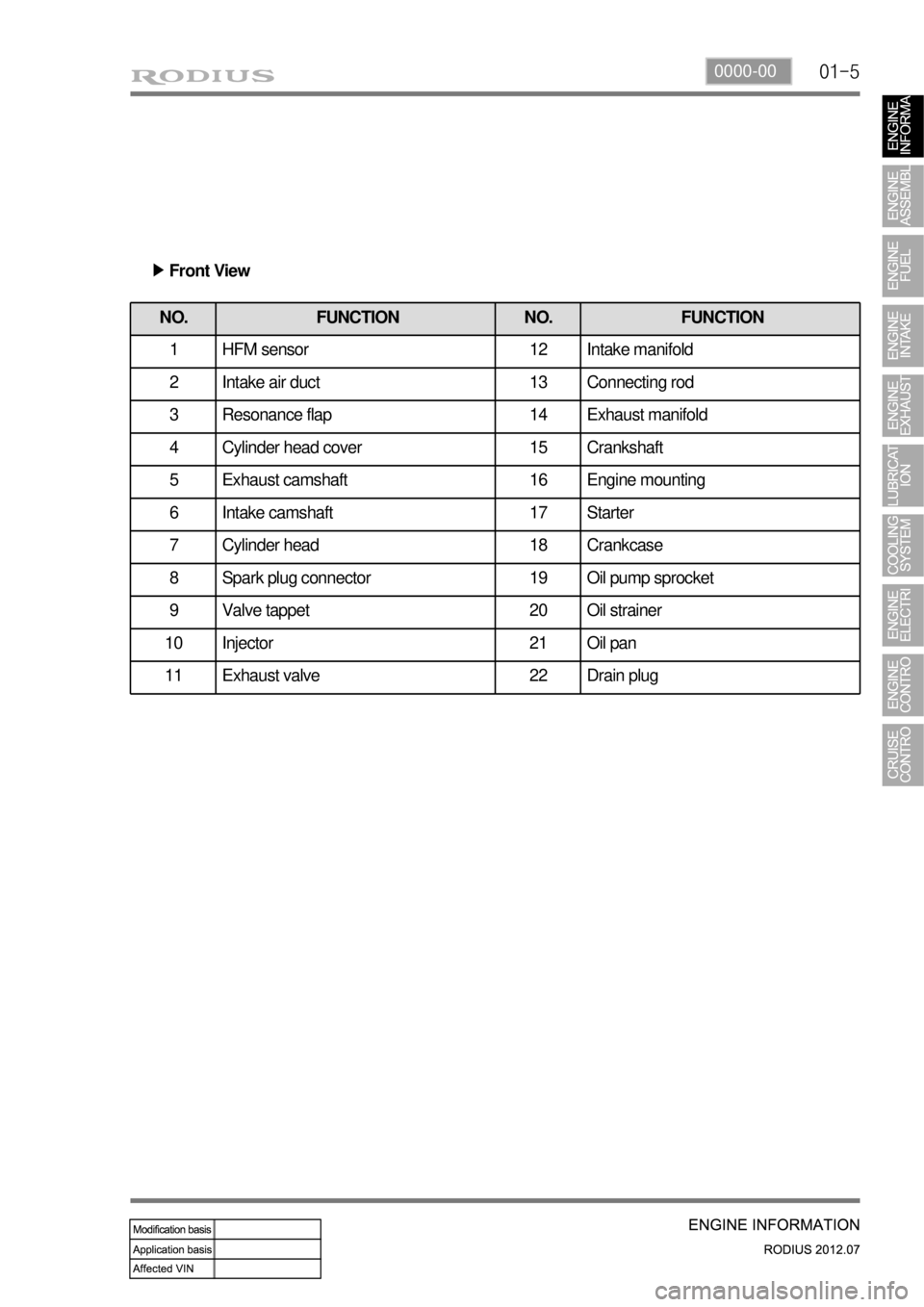
NO. FUNCTION NO. FUNCTION
1 HFM sensor 12 Intake manifold
2 Intake air duct 13 Connecting rod
3 Resonance flap 14 Exhaust manifold
4 Cylinder head cover 15 Crankshaft
5 Exhaust camshaft 16 Engine mounting
6 Intake camshaft 17 Starter
7 Cylinder head 18 Crankcase
8 Spark plug connector 19 Oil pump sprocket
9 Valve tappet 20 Oil strainer
10 Injector 21 Oil pan
11 Exhaust valve 22 Drain plug
Front View ▶
Page 378 of 715

01-6
2) Side View
NO. FUNCTION NO. FUNCTION
23 Camshaft adjuster 27 Oil pump drive chain
24 Cooling fan and viscous clutch 28 Oil return pipe
25 Piston 29 Timing chain
26 Flywheel of drive plate
Page 379 of 715
01-70000-00
2. DESCRIPTION AND OPERATION
1) Cleanliness and Care
An automobile engine is a combination of many machined, honed, polished and lapped surfaces
with tolerances that are measured in the ten-thousanths of an inch. When any internal engine
parts are serviced, care and cleanliness are important. A liberal coating of enigne oil should be
applied to friction areas during assembly, to protect and lubricate the surfaces on initial operation.
Proper cleaning and protection of machined surfaces and friction areas is part of the repair
procedure. This is considered standard shop practice even if not specifically stated.
Whenever valve train components are removed for service, they should be kept in order.
They should be installed in the same locations, and with the same mating surfaces, as when they
were removed. Battery cables should be disconnected before any major work is performed on the
engine. Failure to disconnect cables may result in damage to wire harness or other electrical
parts.
2) On-Engine Service
Disconnect the negative battery cable before removing or installing any electrical unit, or
when a tool or equipment could easily come in contact with exposed electrical terminals.
Disconnecting this cable will help prevent personal injury and damage to the vehicle.
The ignition must also be in LOCK unless otherwise noted.
Notice Any time the air cleaner is removed, the intake opening -
Any time the air cleaner is removed, the intake opening should be covered. This will protect
against accidental entrance of foreign material, which could follow the intake passage into
the cylinder and cause extensive damage when the engine is started.g -
Page 392 of 715
06-39210-01
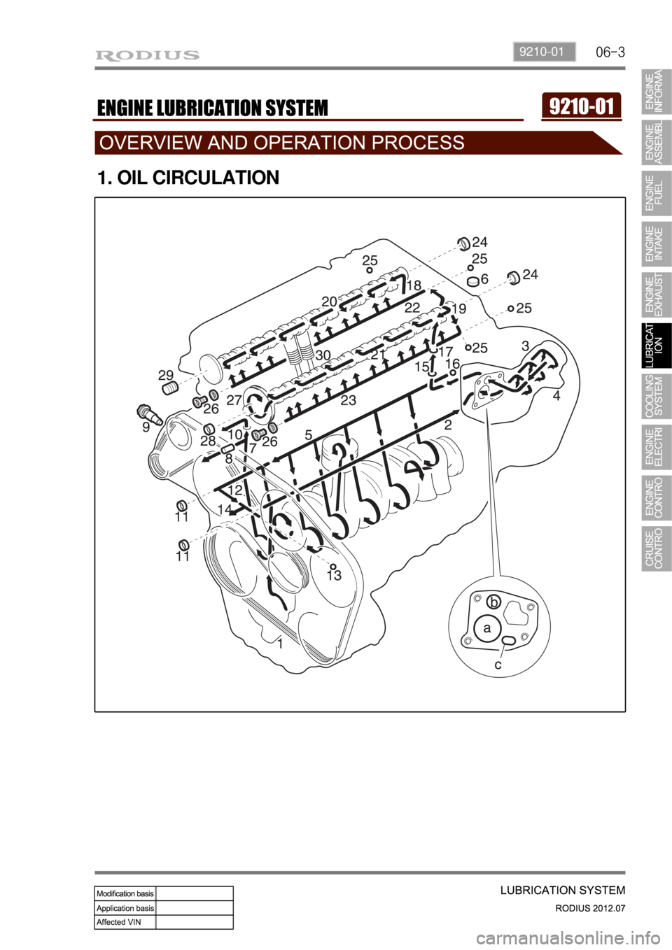
1. OIL CIRCULATION
Page 393 of 715

06-4
NO. FUNCTION NO. FUNCTION
1 Oil pump 18 Oil supply (to exhaust camshaft)
2 Oil gallery (to oil filter) 19 Oil supply (to intake camshaft)
3 Oil filter 20Oil supply
(to exhaust camshaft bearing)
4 Oil pressure switch 21Oil supply
(to intake camshaft bearing)
5 Main oil gallery 22Oil gallery
(oil supply to exhaust valve tappet)
6 Cylinder head closing cover 23Oil gallery
(oil supply to intake valve tappet)
7 Oil gallery (at chain tensioner) 24 Camshaft closing cover
8 Oil non-return valve 25Ball (φ 8 mm)
9 Chain tensioner 26 Screw plug
10 Vent (chain tensioner) 27 Camshaft adjuster
11Front closing cover (φ 17 mm)28Front closing cover
(intake camshaft)
12Oil gallery
(perpendicular to the shaft)29Front treaded bushing
(exhaust camshaft)
13Ball (φ 6 mm)30 Valve tappet
14 Oil spray nozzle (timing chain) aOil gallery
(from oil pump to oil filter)
15 Oil gallery (at cylinder head) b Main oil gallery
16Ball (φ 15mm)cOil return line
(oil returns to the oil pan when
replacing the filter element)
17Oil restriction inner (φ 4mm)
OIL CIRCULATION ▶