oil SSANGYONG RODIUS 2012 Repair Manual
[x] Cancel search | Manufacturer: SSANGYONG, Model Year: 2012, Model line: RODIUS, Model: SSANGYONG RODIUS 2012Pages: 715, PDF Size: 79.36 MB
Page 403 of 715
08-6
3. IGNITION SYSTEM OPERATION
This ignition system does not use a conventional distributor and coil. It uses a crankshaft position
sensor input to the Engine Control Module (ECM).
The ECM then determines Electronic Spark Timing (EST) and triggers the electronic ignition
system ignition coil.
This type of distributorless ignition system uses a "waste spark" method of spark distribution.
Each cylinder is paired with the cylinder that is opposite it (2.3L DOHC: 2 - 3 or 1 - 4, 3.2L
DOHC: 1 - 6 or 2 - 5 or 3 - 4).
The spark occurs simultaneously in the cylinder coming up on the compression stroke and in the
cylinder coming up on the exhaust stroke.
The cylinder on the exhaust stroke requires very little of the available energy to fire the spark plug.
The remaining energy is available to the spark plug in the cylinder on the compression stroke.
These systems use the EST signal from the ECM to control the EST.
The ECM uses the following information: Engine load (mass air flow sensor, manifold air pressure
sensor).
Engine coolant temperature.
Intake air temperature.
Crankshaft position.
Engine speed (rpm).
1) Electronic Ignition System Ignition Coil
The Electronic Ignition (EI) system ignition coil is located on the cylinder head cover.
The double ended coils re ceive the signal for the ECM which controls the spark advance.
Each EI system ignition coil provides the high voltage to two spark plugs simultaneously;
3.2L DOHC
T1/1: cylinder 2 and 5
T1/2: cylinder 3 and 4
T1/3: cylinder 1 and 6
The EI system ignition coil is not serviceable and must be replaced as an assembly.
Page 522 of 715

01-33650-01
Diameter( Torque converter) 270mm
Lockup function Yes
Gear ratios 1st 3.595
2nd 2.186
3rd 1.405
4th 1.000
5th 0.831
Reverse:
S mode / W mode3.167/1.926
Driving type 2WD(4WD)
Fluid specification Shell ATF 134
Fluid capacityapprox. 8ℓ
Selected lever
indicationP.R.N.D Mechanical
D+/D- Electrical
Parking lock systemBrake switch(signal) → TGS lever
Reverse lock systemCAN → TGS lever
Selected lever
indicationP.R.N.D Lever position
1, 2, 3, 4, 5 CAN
Oil temperature
sensorResistance: R, D0.5 ~ 2.5kΩ
Resistance: P, N20kΩ
TCU EGS 52
Shift solenoid
valve(25℃)Resistance3.8 ± 0.2Ω
Operating distance 0.2mm
Operating current 1.5 ~ 2A
Item W5A580(2WD) / W5A400(4WD)
Input torque 450Nm
1. SPECIFICATIONS
Page 527 of 715
01-8
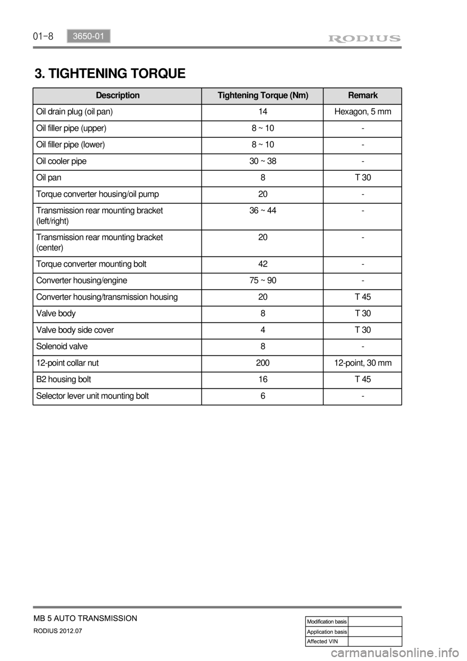
3. TIGHTENING TORQUE
Description Tightening Torque (Nm) Remark
Oil drain plug (oil pan) 14 Hexagon, 5 mm
Oil filler pipe (upper) 8 ~ 10 -
Oil filler pipe (lower) 8 ~ 10 -
Oil cooler pipe 30 ~ 38 -
Oil pan 8 T 30
Torque converter housing/oil pump 20 -
Transmission rear mounting bracket
(left/right)36 ~ 44 -
Transmission rear mounting bracket
(center)20 -
Torque converter mounting bolt 42 -
Converter housing/engine 75 ~ 90 -
Converter housing/transmission housing 20 T 45
Valve body 8 T 30
Valve body side cover 4 T 30
Solenoid valve 8 -
12-point collar nut 200 12-point, 30 mm
B2 housing bolt 16 T 45
Selector lever unit mounting bolt 6 -
Page 540 of 715

01-213650-01
▶Solenoid, Oil temperature sensor, Speed sensor (N2, N3)
Page 543 of 715

02-53170-01
Part No. & Name Appearance Description
Part No.:
SSM00203-005
Name:
Main shaft 1st
sleeve installer
Part No.:
SSM00203-006
Name:
Main shaft reverse
sleeve installer
Part No.:
SSM00203-002
Name:
Main shaft 5th
sleeve installer
Part No.:
SSM00203-003
Name:
Oil seal installerInstall the extension housing oil seal
Part No.:
SSM00203-004
Name:
Oil seal installerInstall the control shaft oil seal
3. SPECIAL SERVICE TOOLS
Install the main shaft 1st gear sleeve
Install the drive pinion assembly front ball
bearing
Install the main shaft double angular ball
bearing -
-
-
Install the main shaft 5th gear sleeve
Install the counter shaft 6th gear sleeve
Install the counter shaft reverse gear
Install the main shaft ball bearing -
-
-
-
Install the main shaft reverse sleeve and
bearing
Install the main drive pinion assembly front
ball bearing
Install the main shaft double angular ball
bearing
Install the 3rd & 4th synchronizer hub
Install the main shaft 5th gear
Install the main shaft 6th gear -
-
-
-
-
-
Page 545 of 715

02-73170-01
4. TIGHTENING TORQUE
Part nameTightening torque
(Nm)Numbers
Adhesive
1. Seal bolt (rolling plunger and guide spring) 53.9~67.6 1EA Loctite
2. Guide bolt 14.7~21.5 1EA Loctite
3. Pocket ball bearing bolt 29.4~41.1 1EA Loctite
4. Reverse shift fork retainer bolt 53.9~67.6 2EA Loctite
5. Backup lamp switch 29.4~34.3 1EA Loctite
6. Oil drain plug 58.8~78.4 1EA Loctite
7. Interlock bolt 14.7~21.5 1EA -
8. Neutral switch 29.4~34.3 1EA Loctite
9. Oil filler plug 58.8~78.4 1EA Loctite
10. Extension housing 42.1~53.9 12EA -
11. Concentric slave cylinder bolt 9.8~15.6 3EA -
12. Front bearing retainer bolt 19.6~24.5 8EA Loctite
Page 546 of 715
02-8
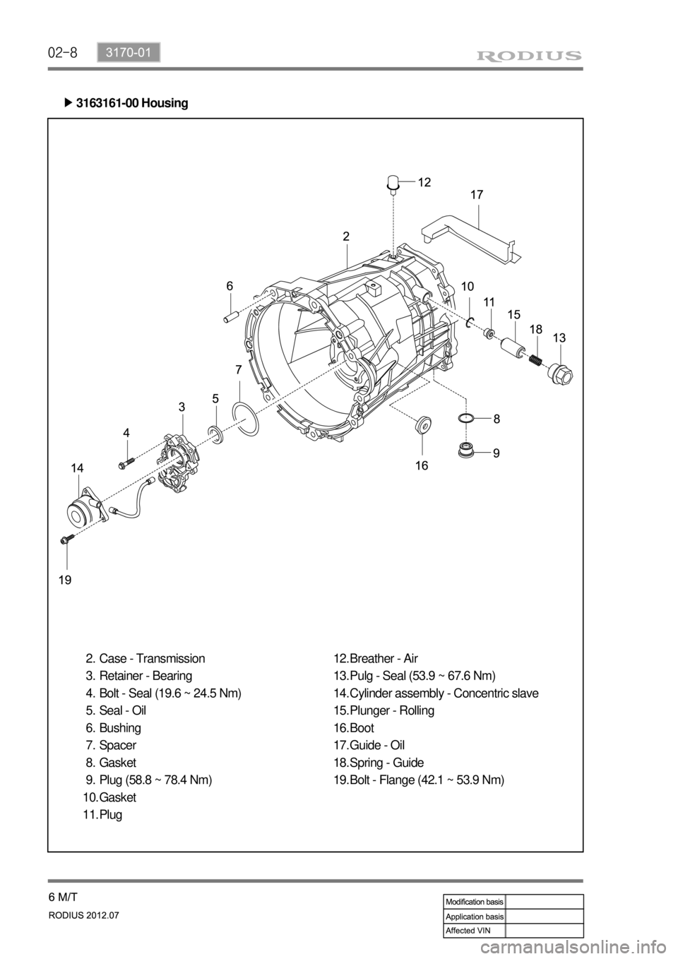
3163161-00 Housing ▶
Case - Transmission
Retainer - Bearing
Bolt - Seal (19.6 ~ 24.5 Nm)
Seal - Oil
Bushing
Spacer
Gasket
Plug (58.8 ~ 78.4 Nm)
Gasket
Plug 2.
3.
4.
5.
6.
7.
8.
9.
10.
11.Breather - Air
Pulg - Seal (53.9 ~ 67.6 Nm)
Cylinder assembly - Concentric slave
Plunger - Rolling
Boot
Guide - Oil
Spring - Guide
Bolt - Flange (42.1 ~ 53.9 Nm) 12.
13.
14.
15.
16.
17.
18.
19.
Page 550 of 715
02-12
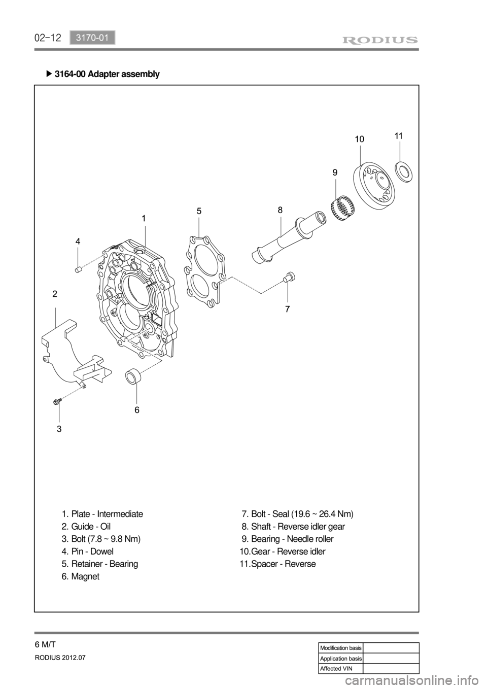
3164-00 Adapter assembly ▶
Plate - Intermediate
Guide - Oil
Bolt (7.8 ~ 9.8 Nm)
Pin - Dowel
Retainer - Bearing
Magnet 1.
2.
3.
4.
5.
6.Bolt - Seal (19.6 ~ 26.4 Nm)
Shaft - Reverse idler gear
Bearing - Needle roller
Gear - Reverse idler
Spacer - Reverse 7.
8.
9.
10.
11.
Page 552 of 715
02-14
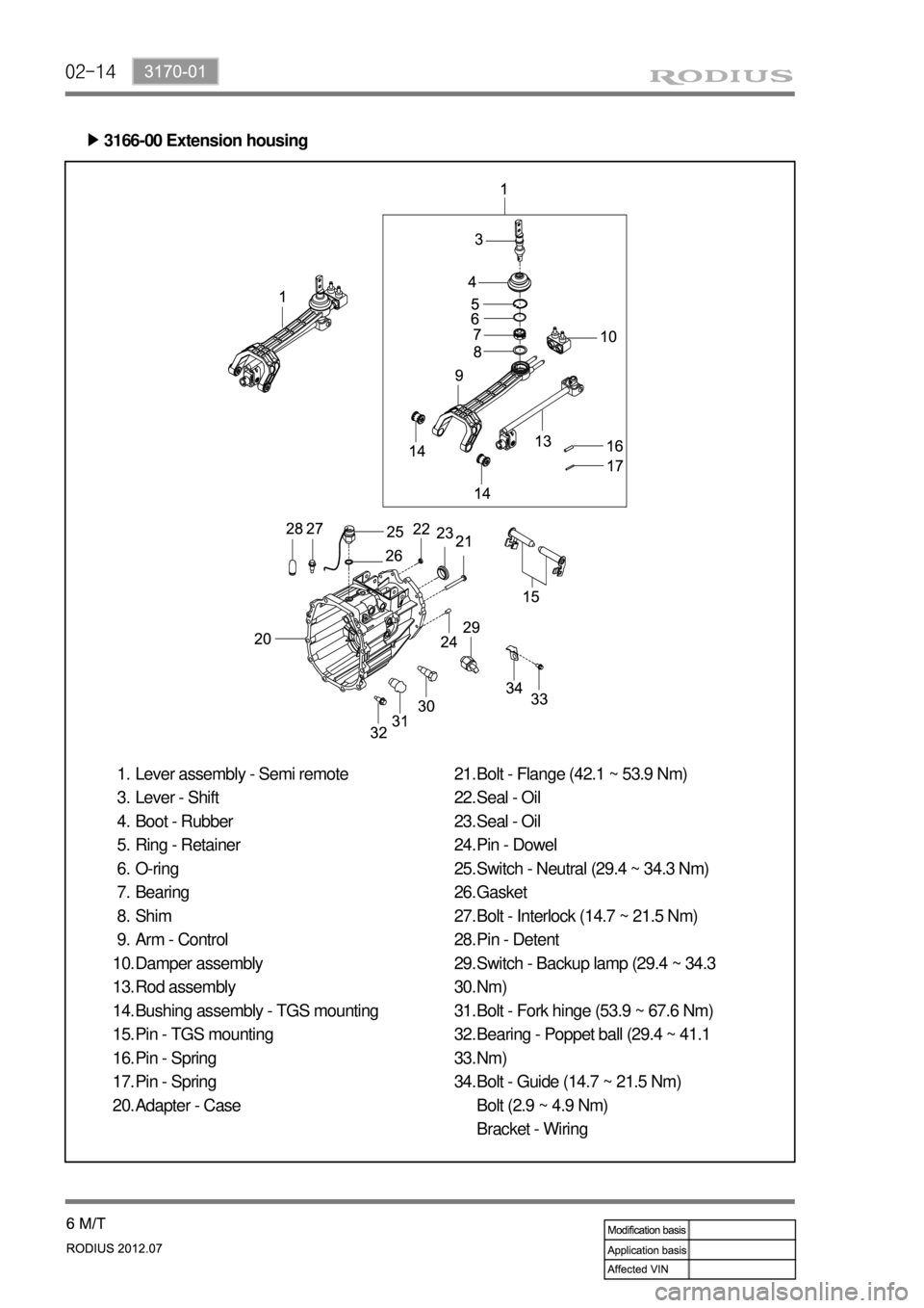
3166-00 Extension housing ▶
Lever assembly - Semi remote
Lever - Shift
Boot - Rubber
Ring - Retainer
O-ring
Bearing
Shim
Arm - Control
Damper assembly
Rod assembly
Bushing assembly - TGS mounting
Pin - TGS mounting
Pin - Spring
Pin - Spring
Adapter - Case 1.
3.
4.
5.
6.
7.
8.
9.
10.
13.
14.
15.
16.
17.
20.Bolt - Flange (42.1 ~ 53.9 Nm)
Seal - Oil
Seal - Oil
Pin - Dowel
Switch - Neutral (29.4 ~ 34.3 Nm)
Gasket
Bolt - Interlock (14.7 ~ 21.5 Nm)
Pin - Detent
Switch - Backup lamp (29.4 ~ 34.3
Nm)
Bolt - Fork hinge (53.9 ~ 67.6 Nm)
Bearing - Poppet ball (29.4 ~ 41.1
Nm)
Bolt - Guide (14.7 ~ 21.5 Nm)
Bolt (2.9 ~ 4.9 Nm)
Bracket - Wiring 21.
22.
23.
24.
25.
26.
27.
28.
29.
30.
31.
32.
33.
34.
Page 568 of 715
03-113010-00
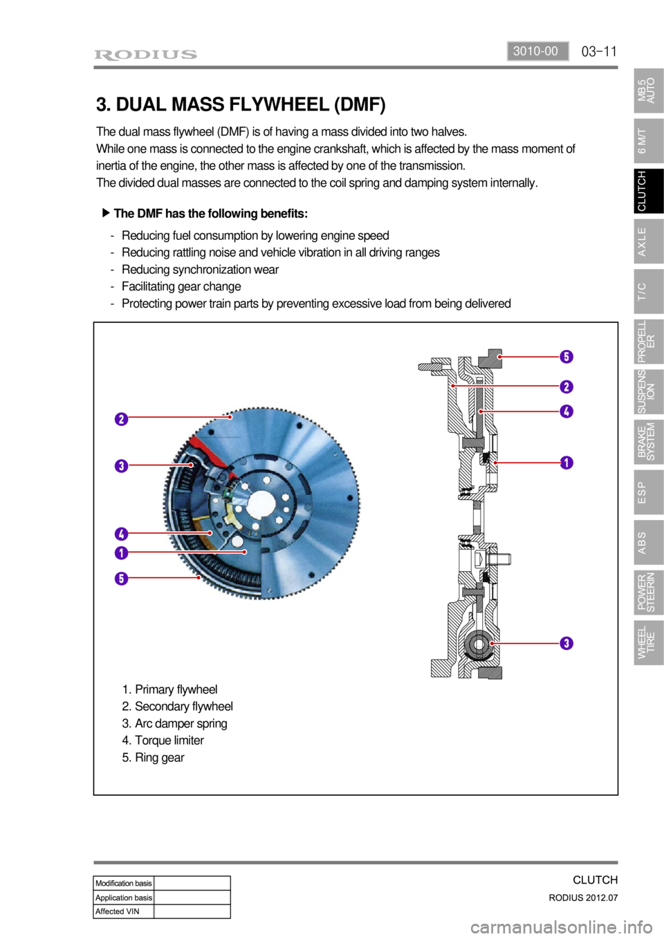
3. DUAL MASS FLYWHEEL (DMF)
The dual mass flywheel (DMF) is of having a mass divided into two halves.
While one mass is connected to the engine crankshaft, which is affected by the mass moment of
inertia of the engine, the other mass is affected by one of the transmission.
The divided dual masses are connected to the coil spring and damping system internally.
The DMF has the following benefits: ▶
Reducing fuel consumption by lowering engine speed
Reducing rattling noise and vehicle vibration in all driving ranges
Reducing synchronization wear
Facilitating gear change
Protecting power train parts by preventing excessive load from being delivered -
-
-
-
-
Primary flywheel
Secondary flywheel
Arc damper spring
Torque limiter
Ring gear 1.
2.
3.
4.
5.