coolant flow SSANGYONG RODIUS 2012 Service Manual
[x] Cancel search | Manufacturer: SSANGYONG, Model Year: 2012, Model line: RODIUS, Model: SSANGYONG RODIUS 2012Pages: 715, PDF Size: 79.36 MB
Page 206 of 715

02-490000-00
The bottom side of water jacket is desgined as sine wave to strengthen the structure of crankcase.
The main flow of coolant starts from outlet port of water pump and goes along the longitudinal
direction of engine. The coolant passage from cylinder head to inlet port of water pump is
integrated in cylinder head.
The engine oil from oil pump is supplied to the main oil gallery through oil channel, oil filter
module and cross bore in cylinder block without using external pipes. This oil is supplied to main
bearing, cylinder head and MBU. And, it is sprayed to the chain through the chain tensioner
connected to cross bore.
Crankcase cross bore for oil supply
Water jacket core
Page 230 of 715

03-26
The engine ECU calculates the accelerator pedal based on the input signals from various sensors,
and controls the overall operation of the vehicle.
The ECU receives the signals from various sensor through data line, and performs effective air-fuel
ratio control based on these signals.
The crankshaft speed (position) sensor measures the engine speed, and the camshaft speed
(position) sensor determines the order of injections, and the ECU detects the amount of the
accelerator pedal depressed (driver's will) by receiving the electrical signals from the accelerator
pedal sensor.
The mass air flow sensor detects the volume of intake air and sends the value to the ECU.
The major function of the ECU is controlling air-fuel ratio to reduce the emission level (EGR valve
control) by detecting instantaneous air flow change with the signals from the mass air flow sensor.
Also, the ECU uses the signals from the coolant temperature & air temperature sensors, booster
pressure sensor, atmospheric pressure sensor to: a) determine injection starting point and set
value for pilot injection, and b) deal with various operations and variable conditions.
Page 268 of 715

08-31520-00
1. SPECIFICATION
Description Specification
Cooling system Type Water cooling, forced circulation
Coolant Capacity approx. 11.5 L
RadiatorCore size589W x 538H x 27T (over 3,170 cm²)
Flow type Cross flow
AntifreezeType Long life coolant
Mixing ratio
(water:antifreeze)50 : 50
Cooling fan
moduleMotor type DC motor
Motor weight 2.14 kg
Control type PWM type
Fan runout 3 mm
Coolant reservoirCapacity over 1.5 L
Circulation Closed roof type
Pressure cap Screw type
Pressure 1.4bar
ThermostatType Wax pallet type
Opening temperature90 ℃
Fully open temperature
100℃
Valve lift 8mm
Page 273 of 715

08-8
Coolant reservoir
Oil filter module
Thermostat
When the engine coolant
reaches 90℃, the thermostat
starts to open (fully open at
100℃) and lets the coolant
flow to the radiator to
maintain the engine
temperature.
Water pump
The water pump is driven by the engine drive belt and
supplies the coolant to each area of the engine.
1. SYSTEM DESCRIPTION
1) Overview
Water pump Impeller vaneSealing
Page 328 of 715

15-30000-00
1. ENGINE DATA LIST
Data Unit Value
Coolant temperature℃ 130℃~-40℃
Intake air temperature℃ -40 to 130℃ (varies by ambient air
temperature or engine mode)
Idle speed rpm 700 ± 50 (P/N), 600 ± (D)
Engine load % 18~25%
Mass air flow kg/h 16 to 25 kg/h
Throttle position angle°TA 0° (Full Open) to 78° (Close)
Engine torque Nm varies by engine conditions
Injection time ms 3 to 5ms
Battery voltage V 13.5 V to 14.1 V
Accelerator pedal position 1 V 0.4. to 4.8V
Accelerator pedal position 2 V 0.2 to 2.4 V
Throttle position 1 V 0.3 to 4.6 V
Throttle position 2 V 0.3 to 4.6 V
Oxygen sensor V 0 to 5 V
A/C compressor switch
1=ON / 0=OFF -
Full load 1=ON / 0=OFF -
Gear selection (A/T) 1=ON / 0=OFF -
Knocking control 1=ON / 0=OFF -
Brake switch 1=ON / 0=OFF -
Cruise control 1=ON / 0=OFF -
Page 340 of 715
15-150000-00
(3) Fuel Pressure Control
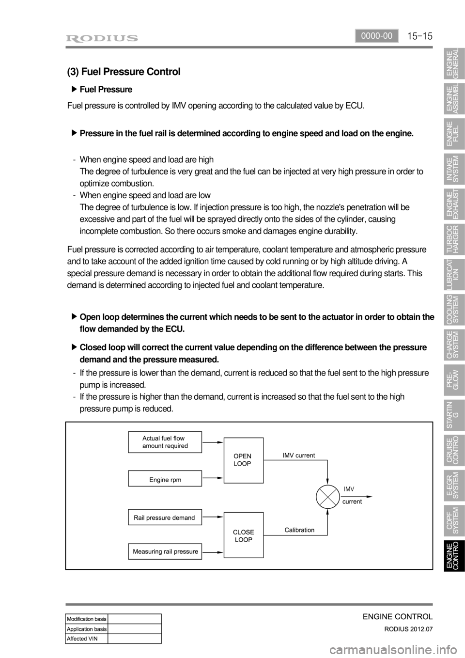
Fuel pressure is controlled by IMV opening according to the calculated value by ECU.
Pressure in the fuel rail is determined according to engine speed and load on the engine. ▶
When engine speed and load are high
The degree of turbulence is very great and the fuel can be injected at very high pressure in order to
optimize combustion.
When engine speed and load are low
The degree of turbulence is low. If injection pressure is too high, the nozzle's penetration will be
excessive and part of the fuel will be sprayed directly onto the sides of the cylinder, causing
incomplete combustion. So there occurs smoke and damages engine durability. -
-
Fuel pressure is corrected according to air temperature, coolant temperature and atmospheric pressure
and to take account of the added ignition time caused by cold running or by high altitude driving. A
special pressure demand is necessary in order to obtain the additional flow required during starts. This
demand is determined according to injected fuel and coolant temperature.
Open loop determines the current which needs to be sent to the actuator in order to obtain the
flow demanded by the ECU. ▶
Closed loop will correct the current value depending on the difference between the pressure
demand and the pressure measured. ▶
If the pressure is lower than the demand, current is reduced so that the fuel sent to the high pressure
pump is increased.
If the pressure is higher than the demand, current is increased so that the fuel sent to the high
pressure pump is reduced. -
-Fuel Pressure ▶
Page 341 of 715
15-16
Pilot injection timing control ▶
The pilot injection timing is determined as a function of the engine speed and of the total flow.
The elements are:
A first correction is made according to the air and coolant temperatures. This correction allows the
pilot injection timing to be adapted to the operating temperature of the engine.
A second correction is made according to the atmospheric pressure. This correction is used to adapt
the pilot injection timing as a function of the atmospheric pressure and therefore the altitude. -
-
(4) Injection Timing Control
Injection timing is determined by the conditions below. ▶
Coolant temperature
Hot engine - Retarded to reduce Nox
Cold engine - Advanced to optimize the combustion 1.
Atmospheric pressure
Advanced according to the altitude 2.
Warming up
Advanced during warming up in cold engine 3.
Rail pressure
Retarded to prevent knocking when the rail pressure is high 4.
EEGR ratio
Advanced to decrease the cylinder temperature when EGR ratio increases 5.
Main injection timing control ▶
The pulse necessary for the main injection is determined as a function of the engine speed and of the
injected flow.
The elements are:
A first correction is made according to the air and coolant temperatures.
This correction makes it possible to adapt the timing to the operating temperature of the engine.
When the engine is warm, the timing can be retarded to reduce the combustion temperature and
polluting emissions (NOx). When the engine is cold, the timing advance must be sufficient to allow
the combustion to begin correctly.
A second correction is made according to the atmospheric pressure.
This correction is used to adapt the timing advance as a function of the atmospheric pressure and
therefore the altitude.
A third correction is made according to the coolant temperature and the time which has passed since
starting.
This correction allows the injection timing advance to be increased while the engine is warming up
(initial 30 seconds). The purpose of this correction is to reduce the misfiring and instabilities which are
liable to occur after a cold start. -
-
-
Page 342 of 715

15-170000-00
A fourth correction is made according to the pressure error.
This correction is used to reduce the injection timing advance when the pressure in the rail is higher
than the pressure demand.
A fifth correction is made according to the rate of EGR.
This correction is used to correct the injection timing advance as a function of the rate of exhaust gas
recirculation. -
-
When the EGR rate increases, the injection timing advance must in fact be increased in order to
compensate for the fall in termperature in the cylinder.
A. Main Flow Control
The main flow represents the amount of fuel injected into the cylinder during the main injection. The pilot
flow represents the amount of fuel injected during the pilot injection.
The total fuel injected during 1 cycle (main flow + pilot flow) is determined in the following manner.
When the driver depress the pedal, it is his demand which is taken into account by the system in order
to determine the fuel injected.
When the driver release the pedal, the idle speed controller takes over to determine the minimum fuel
which must be injected into the cylinder to prevent the enigne from stalling. -
-
The driver demand is the translation of the pedal position into the fuel demand. It is calculated as a
function of the pedal position and of the engine speed. The driver demand is filtered in order to limit the
hesitations caused by rapid changes of the pedal position. A mapping determines the maximum fuel
which can be injected as a function of the driver demand and the rail pressure. Since the flow is
proportional to the injection time and to the square root of the injection pressure, it is necessary to limit
the flow according to the pressure in order to avoid extending the injection for too long into the engine
cycle. The system compares the driver demand with this limit and chooses the smaller of the 2 values.
The driver demand is then corrected according to the coolant temperature. This correction is added to
the driver demand.
(5) Fuel Control
B. Driver Demand
Page 343 of 715
15-18
C. Idle Speed Controller
The idle speed controller consists of 2 principal modules:
The first module determines the required idle speed according to:
* The operating conditions of the engine (coolant temperature, gear engaged)
* Any activation of the electrical consumers (power steering, air conditioning, others)
* The battery voltage
* The presence of any faults liable to interface with the rail pressure control or the injection control. In
this case, increase the idle speed to prevent the engine from stalling.
The second module is responsible for providing closed loop control of the engine's idle speed by
adapting the minimum fuel according to the difference between the required idle speed and the
engine speed. -
-
D. Flow Limitation
The flow limitation strategy is based on the following strategies:
The flow limitation depending on the filling of the engine with air is determined according to the
engine speed and the air flow. This limitation allows smoke emissions to be reduced during
stabilized running.
The flow limitation depending on the atmospheric pressure is determined according to the engine
speed and the atmospheric pressure. It allows smoke emissions to be reduced when driving at
altitude.
The full load flow curve is determined according to the gear engaged and the engine speed. It
allows the maximum torque delivered by the engine to be limited.
A performance limitation is introduced if faults liable to upset the rail pressure control or the
injection control are detected by the system. In this case, and depending on the gravity of the fault,
the system activates: -
-
-
-
Reduced fuel logic 1: Guarantees 75 % of the performance without limiting the engine speed.
Reduced fuel logic 2: Guarantees 50 % of the performance with the engine speed limited to
3,000 rpm.
Reduce fuel logic 3: Limits the engine speed to 2,000 rpm.
The system chooses the lowest of all values.
A correction depending on the coolant temperature is added to the flow limitation. This correction makes
it possible to reduce the mechanical stresses while the engine is warming up.
The correction is determined according to the coolant temperature, the engine speed and the time which
has passed since starting.
E. Superchager Flow Demand
The supercharge flow is calculated according to the engine speed and the coolant temperature. A
correction depending on the air temperature and the atmospheric pressure is made in order to increase
the supercharge flow during cold starts. It is possible to alter the supercharge flow value by adding a flow
offset with the aid of the diagnostic tool
Page 344 of 715
15-190000-00
F. Pilot Flow Control
The pilot flow represents the amount of fuel injected into the cylinder during the pilot injection. This
amount is determined according to the engine speed and the total flow.
A first correction is made according to the air and water temperature.
This correction allows the pilot flow to be adapted to the operating temperature of the engine. When
the engine is warm, the ignition time decreases because the end-of-compression temperature is
higher. The pilot flow can therefore be reduced because there is obviously less combustion noise
when the engine is warm.
A second correction is made according to the atmospheric pressure. -
-
During starting, the pilot flow is determined on the basis of the engine speed and the coolant
temperature.
G. Cylinder Balancing Strategy
Balancing of the point to point flows ▶
The pulse of each injector is corrected according to the difference in instantaneous speed measured
between 2 successive injectors.
The instantaneous speeds on two successive injections are first calculated.
The difference between these two instantaneous speeds is then calculated.
Finally, the time to be added to the main injection pulse for the different injectors is determined.
For each injector, this time is calculated according to the initial offset of the injector and the
instantaneous speed difference.
Detection of an injector which has stuck closed ▶
The cylinder balancing strategy also allows the detection of an injector which has stuck closed. The
difference in instantaneous speed between 2 successive injections then exceeds a predefined threshold.
In this case, a fault is signaled by the system.