engine SSANGYONG TURISMO 2013 Service Manual
[x] Cancel search | Manufacturer: SSANGYONG, Model Year: 2013, Model line: TURISMO, Model: SSANGYONG TURISMO 2013Pages: 796, PDF Size: 78.99 MB
Page 591 of 796

03-53010-00
3. INSPECTION
Pedal stroke and height ▶
Pedal stroke (A)
A.
Stop the engine.
Measure the current pedal position.
Depress the clutch pedal all the way and
measure the pedal stroke (A). 1)
2)
3)
Stroke (A)150 ± 3 mm
Pedal height (B) B.
Stop the engine.
Remove the floor mat from the driver’s
footwall.
Measure the pedal height (B). 1)
2)
3)
Height (B)95.2 ± 3 mm
Adjustment-
Release the lock nut (D) on stopper bolt (C).
Turn the stopper bolt to adjust the pedal
height.
Tighten the lock nut to the specified tightening
torque. 1)
2)
3)
Page 592 of 796

03-6
Pedal free play ▶
Pedal free play (A) A.
Stop the engine.
Measure the current pedal position.
Lightly depress the clutch pedal until you feel
the resistance from the pedal and measure
the distance. 1)
2)
3)
Free play (A)5 ~ 15 mm
Adjustment-
Release the lock nut (B) from the master
cylinder.
Turn the push rod (C) to adjust the pedal
free play.
Tighten the lock nut to the specified
tightening torque. 1)
2)
3)
Page 593 of 796

03-73010-00
1. OVERVIEW
The hydraulic clutch transmits the force required to operate the clutch pedal to the concentric slave
cylinder fitted to the clutch housing as a hydraulic pressure.
(The hydraulic pressure is transmitted in the following order: Clutch pedal - Clutch master cylinder -
Clutch pipe - Clutch damper - Clutch pipe and hose - Concentric slave cylinder - Pressure plate -
Flywheel.)
If a driver depress the clutch pedal, the hydraulic pressure is generated in the master cylinder. It is
transmitted to the concentric slave cylinder through the pipe, resulting in the cylinder being forced out.
At this time, the clutch disc is forced against the cylinder by pushing the cover. This, in turn, remove the
flywheel from the pressure plate. As a consequence, the power from the engine will be cut off and the
gear change can be carried out.
Page 595 of 796

03-93010-00
2) Overview
Driving elements ▶
The driving elements consist of two flat surfaces machined to a smooth finish.
One of these is the rear face of the engine flywheel and the other is the clutch pressure plate. The
clutch pressure plate is fitted into a clutch steel cover, which is bolted to the flywheel.
Driven elements ▶
The driven element is the clutch disc with a splined hub which is free to slide lengthwise along the
splines of the input shaft.
The driving and driven elements are held in contact by spring pressure. This pressure is exerted by a
diaphragm spring in the clutch cover pressure plate assembly.
Operating Elements ▶
The clutch "release" system consists of the clutch pedal and clutch release cylinder.
This system directly releases the clutch by using hydraulic pressure while the conventional clutch
system releases the clutch by using release lever and release fork. This system provides higher
efficiency than conventional clutch system, and its durability is superior.
Clutch master cylinder (mounted on clutch pedal)
Concentric slave cylinder pipe (mounted inside of transmission) -
-
Page 597 of 796

03-113010-00
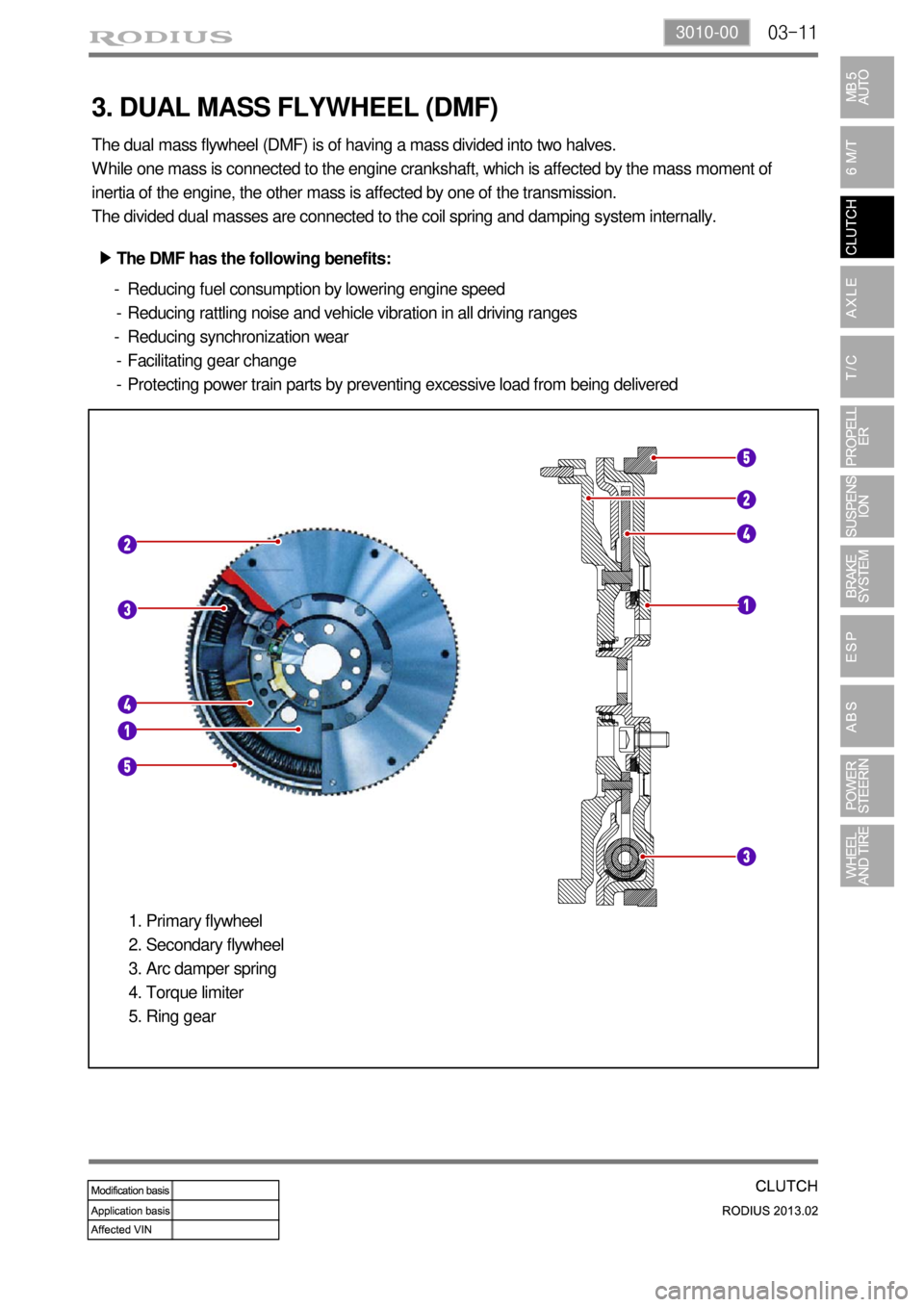
3. DUAL MASS FLYWHEEL (DMF)
The dual mass flywheel (DMF) is of having a mass divided into two halves.
While one mass is connected to the engine crankshaft, which is affected by the mass moment of
inertia of the engine, the other mass is affected by one of the transmission.
The divided dual masses are connected to the coil spring and damping system internally.
The DMF has the following benefits: ▶
Reducing fuel consumption by lowering engine speed
Reducing rattling noise and vehicle vibration in all driving ranges
Reducing synchronization wear
Facilitating gear change
Protecting power train parts by preventing excessive load from being delivered -
-
-
-
-
Primary flywheel
Secondary flywheel
Arc damper spring
Torque limiter
Ring gear 1.
2.
3.
4.
5.
Page 598 of 796

04-34120-01
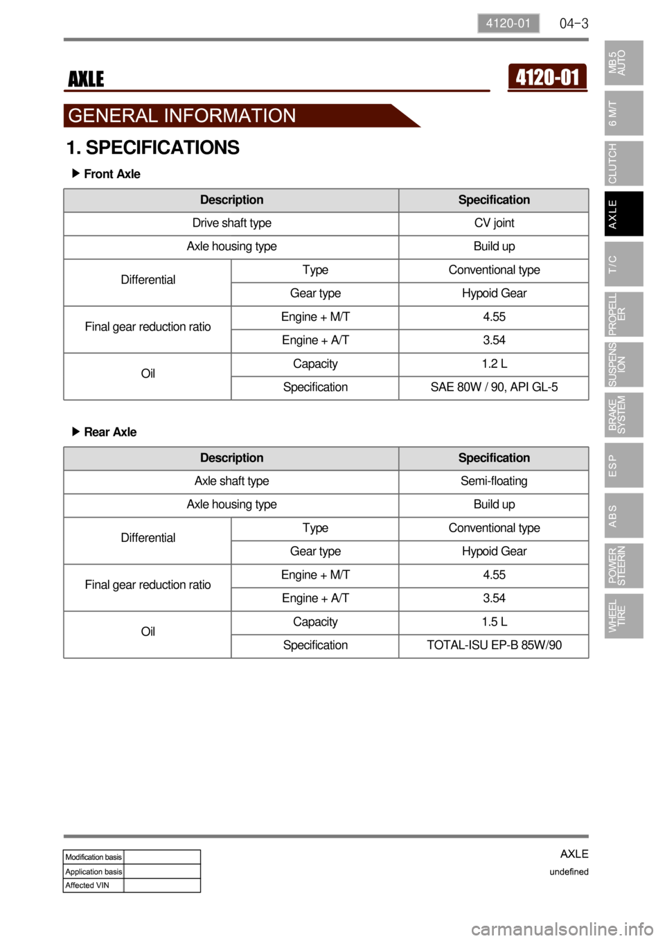
1. SPECIFICATIONS
Front Axle ▶
Rear Axle ▶
Description Specification
Drive shaft type CV joint
Axle housing type Build up
DifferentialType Conventional type
Gear type Hypoid Gear
Final gear reduction ratioEngine + M/T 4.55
Engine + A/T 3.54
OilCapacity 1.2 L
Specification SAE 80W / 90, API GL-5
Description Specification
Axle shaft type Semi-floating
Axle housing type Build up
DifferentialType Conventional type
Gear type Hypoid Gear
Final gear reduction ratioEngine + M/T 4.55
Engine + A/T 3.54
OilCapacity 1.5 L
Specification TOTAL-ISU EP-B 85W/90
Page 600 of 796

04-54120-01
1. OVERVIEW
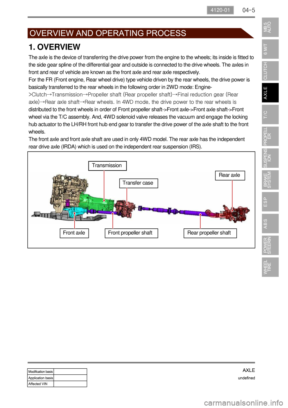
The axle is the device of transferring the drive power from the engine to the wheels; its inside is fitted to
the side gear spline of the differential gear and outside is connected to the drive wheels. The axles in
front and rear of vehicle are known as the front axle and rear axle respectively.
For the FR (Front engine, Rear wheel drive) type vehicle driven by the rear wheels, the drive power is
basically transferred to the rear wheels in the following order in 2WD mode: Engine-
>Clutch→Transmission→Propeller shaft (Rear propeller shaft)→Final reduction gear (Rear
axle)→Rear axle shaft→Rear wheels. In 4WD mode, the drive power to the rear wheels is
distributed to the front wheels in order of Front propeller shaft->Front axle->Front axle shaft->Front
wheel via the T/C assembly. And, 4WD solenoid valve releases the vacuum and engage the locking
hub actuator to the LH/RH front hub end gear to transfer the drive power of the axle shaft to the front
wheels.
The front axle and front axle shaft are used in only 4WD model. The rear axle has the independent
rear drive axle (IRDA) which is used on the independent rear suspension (IRS).
Front axleTransmission
Transfer case
Front propeller shaft Rear propeller shaftRear axle
Page 621 of 796

07-6
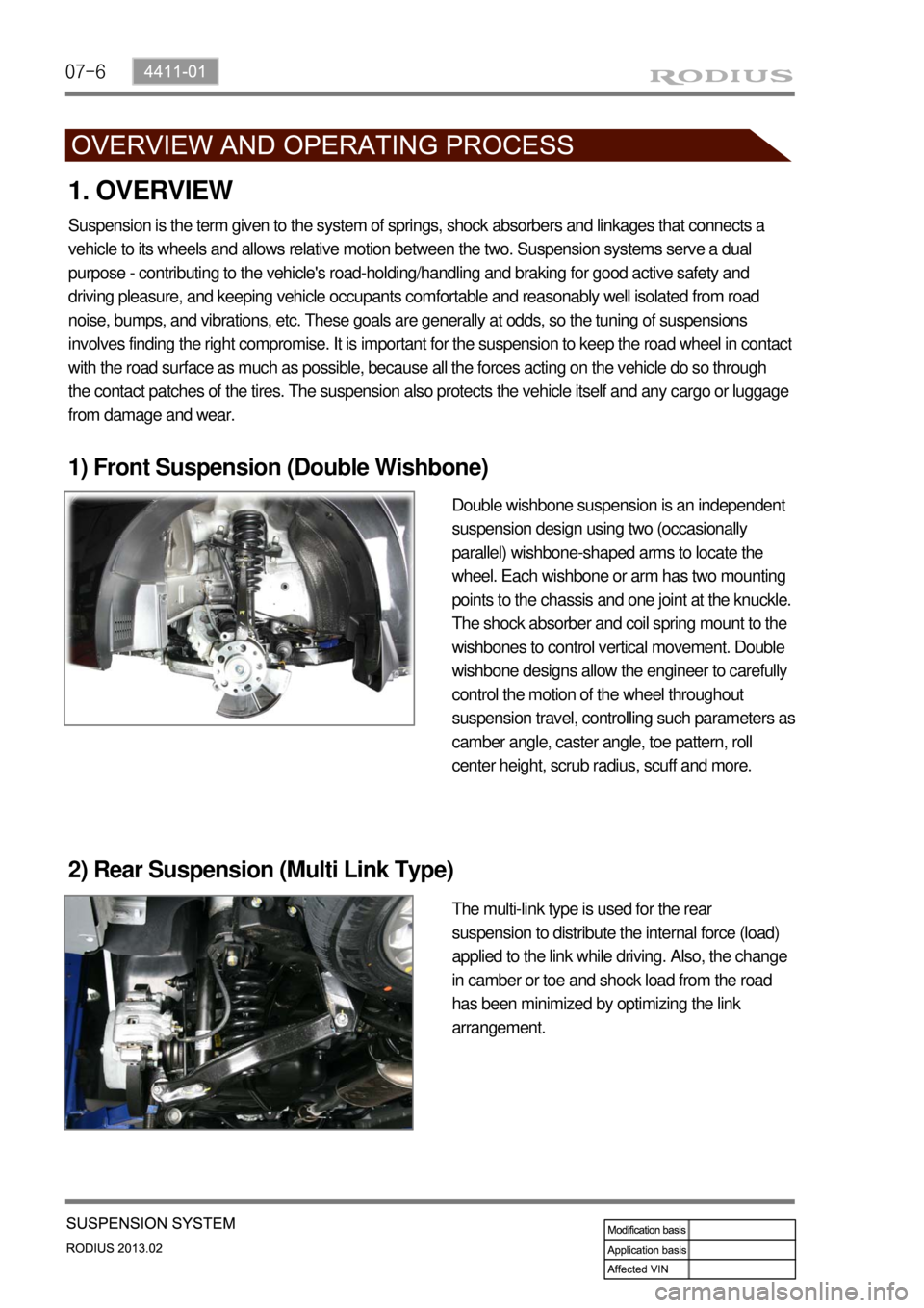
1) Front Suspension (Double Wishbone)
Suspension is the term given to the system of springs, shock absorbers and linkages that connects a
vehicle to its wheels and allows relative motion between the two. Suspension systems serve a dual
purpose - contributing to the vehicle's road-holding/handling and braking for good active safety and
driving pleasure, and keeping vehicle occupants comfortable and reasonably well isolated from road
noise, bumps, and vibrations, etc. These goals are generally at odds, so the tuning of suspensions
involves finding the right compromise. It is important for the suspension to keep the road wheel in contac
t
with the road surface as much as possible, because all the forces acting on the vehicle do so through
the contact patches of the tires. The suspension also protects the vehicle itself and any cargo or luggage
from damage and wear.
2) Rear Suspension (Multi Link Type)
1. OVERVIEW
Double wishbone suspension is an independent
suspension design using two (occasionally
parallel) wishbone-shaped arms to locate the
wheel. Each wishbone or arm has two mounting
points to the chassis and one joint at the knuckle.
The shock absorber and coil spring mount to the
wishbones to control vertical movement. Double
wishbone designs allow the engineer to carefully
control the motion of the wheel throughout
suspension travel, controlling such parameters as
camber angle, caster angle, toe pattern, roll
center height, scrub radius, scuff and more.
The multi-link type is used for the rear
suspension to distribute the internal force (load)
applied to the link while driving. Also, the change
in camber or toe and shock load from the road
has been minimized by optimizing the link
arrangement.
Page 635 of 796

08-8
Problem Cause Action
Burning smell
around tireToo frequent braking in high driving speed Reduce the use of
foot brake/use
engine brake
properly Use only foot brake during downhill driving
Driving with foot on brake pedal Get off the foot from
pedal
Foreign materials such as dirt or sand in brake system Replace: caliper,
wheel cylinder,
master cylinder,
return spring
Broken return spring in shoe assembly Replace
Incorrectly adjusted parking brake cable Adjust
Incorrect wheel or wheel cover
(generating the heat)Replace
Page 639 of 796

08-12
Let the engine run for 1 to 2 minutes and
stop it. If the brake pedal stroke is shortened
as pumping the brake pedal, the system is
normal. If not, the system is defective. 1.
Depress the brake pedal several times with
engine off. If the brake goes down when
starting engine with pedal depressed, the
system is normal. If not, the system is
defective. 2.
If the above three checks are OK, the system is
normal. If any condition is not met, check the
valve, vacuum hose and brake booster.
3) Brake Booster
OK
NG
Engine stopped
Engine running
Depress the brake pedal when the engine is
running. If the pedal height is not changed
for 30 seconds after stopping the engine, the
system is normal. If not, the system is
defective. 3.