AC Assembly SSANGYONG TURISMO 2013 Owner's Manual
[x] Cancel search | Manufacturer: SSANGYONG, Model Year: 2013, Model line: TURISMO, Model: SSANGYONG TURISMO 2013Pages: 796, PDF Size: 78.99 MB
Page 325 of 796

14-132412-02
Collecting PM
→ Regeneration
The engine ECU detects the
amount of PM collected by the
information from the
temperature sensors and
differential pressure sensor.
When the soot is accumulated,
the engine ECU performs post-
injection to increase the
exhaust gas temperature and
burns the collected PM at
approx. 600°C.Oxidation (DOC)
When the exhaust gas enters
into the CDPF assembly, its
CO, HC and PM are reduced
by the redox reaction of the
DOC. The remaining PM is
filtered and collected in CDPF,
and the temperature of the
exhaust gas is increased to
between 450 and 500°C.
5. OPERATING PROCESS
[Configuration and principle of operation]
The exhaust gas
passed through the
exhaust manifold
enters into the CDPF
assembly (at approx
250℃).
Page 382 of 796

01-70000-00
2. DESCRIPTION AND OPERATION
1) Cleanliness and Care
An automobile engine is a combination of many machined, honed, polished and lapped surfaces with
tolerances that are measured in the ten-thousandths of an inch. When any internal engine parts are
serviced, care and cleanliness are important. A liberal coating of engine oil should be applied to friction
areas during assembly, to protect and lubricate the surfaces on initial operation.
Proper cleaning and protection of machined surfaces and friction areas is part of the repair procedure.
This is considered standard shop practice even if not specifically stated.
Whenever valve train components are removed for service, they should be kept in order.
They should be installed in the same locations, and with the same mating surfaces, as when they were
removed. Battery cables should be disconnected before any major work is performed on the engine.
Failure to disconnect cables may result in damage to wire harness or other electrical parts.
2) On-Engine Service
Disconnect the negative battery cable before removing or installing any electrical unit, or when a
tool or equipment could easily come in contact with exposed electrical terminals.
Disconnecting this cable will help prevent personal injury and damage to the vehicle.
The ignition must also be in LOCK unless otherwise noted.
Notice Any time the air cleaner is removed, the intake opening -
Any time the air cleaner is removed, the intake opening should be covered. This will protect
against accidental entrance of foreign material, which could follow the intake passage into the
cylinder and cause extensive damage when the engine is started. -
Page 391 of 796

05-32420-01
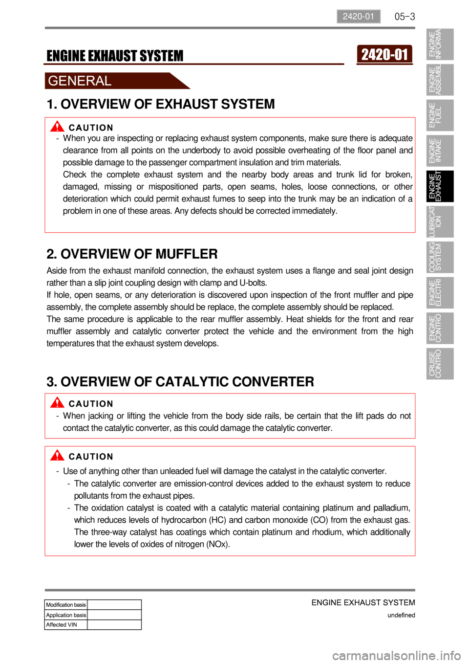
1. OVERVIEW OF EXHAUST SYSTEM
When you are inspecting or replacing exhaust system components, make sure there is adequate
clearance from all points on the underbody to avoid possible overheating of the floor panel and
possible damage to the passenger compartment insulation and trim materials.
Check the complete exhaust system and the nearby body areas and trunk lid for broken,
damaged, missing or mispositioned parts, open seams, holes, loose connections, or othe
r
deterioration which could permit exhaust fumes to seep into the trunk may be an indication of a
problem in one of these areas. Any defects should be corrected immediately. -
2. OVERVIEW OF MUFFLER
Aside from the exhaust manifold connection, the exhaust system uses a flange and seal joint design
rather than a slip joint coupling design with clamp and U-bolts.
If hole, open seams, or any deterioration is discovered upon inspection of the front muffler and pipe
assembly, the complete assembly should be replace, the complete assembly should be replaced.
The same procedure is applicable to the rear muffler assembly. Heat shields for the front and rea
r
muffler assembly and catalytic converter protect the vehicle and the environment from the high
temperatures that the exhaust system develops.
3. OVERVIEW OF CATALYTIC CONVERTER
When jacking or lifting the vehicle from the body side rails, be certain that the lift pads do not
contact the catalytic converter, as this could damage the catalytic converter. -
Use of anything other than unleaded fuel will damage the catalyst in the catalytic converter. -
The catalytic converter are emission-control devices added to the exhaust system to reduce
pollutants from the exhaust pipes.
The oxidation catalyst is coated with a catalytic material containing platinum and palladium,
which reduces levels of hydrocarbon (HC) and carbon monoxide (CO) from the exhaust gas.
The three-way catalyst has coatings which contain platinum and rhodium, which additionall
y
lower the levels of oxides of nitrogen (NOx). -
-
Page 404 of 796

08-6
3. IGNITION SYSTEM OPERATION
This ignition system does not use a conventional distributor and coil. It uses a crankshaft position
sensor input to the Engine Control Module (ECM).
The ECM then determines Electronic Spark Timing (EST) and triggers the electronic ignition system
ignition coil.
This type of distributor less ignition system uses a "waste spark" method of spark distribution. Each
cylinder is paired with the cylinder that is opposite it (2.3L DOHC: 2 - 3 or 1 - 4, 3.2L DOHC: 1 - 6 or 2 -
5 or 3 - 4).
The spark occurs simultaneously in the cylinder coming up on the compression stroke and in the
cylinder coming up on the exhaust stroke.
The cylinder on the exhaust stroke requires very little of the available energy to fire the spark plug.
The remaining energy is available to the spark plug in the cylinder on the compression stroke. These
systems use the EST signal from the ECM to control the EST.
The ECM uses the following information: Engine load (mass air flow sensor, manifold air pressure
sensor).
Engine coolant temperature.
Intake air temperature.
Crankshaft position.
Engine speed (rpm).
1) Electronic Ignition System Ignition Coil
The Electronic Ignition (EI) system ignition coil is located on the cylinder head cover.
The double ended coils receive the signal for the ECM which controls the spark advance. Each
EI system ignition coil provides the high voltage to two spark plugs simultaneously;
3.2L DOHC
T1/1: cylinder 2 and 5
T1/2: cylinder 3 and 4
T1/3: cylinder 1 and 6
The EI system ignition coil is not serviceable and must be replaced as an assembly.
Page 420 of 796

01-78410-02
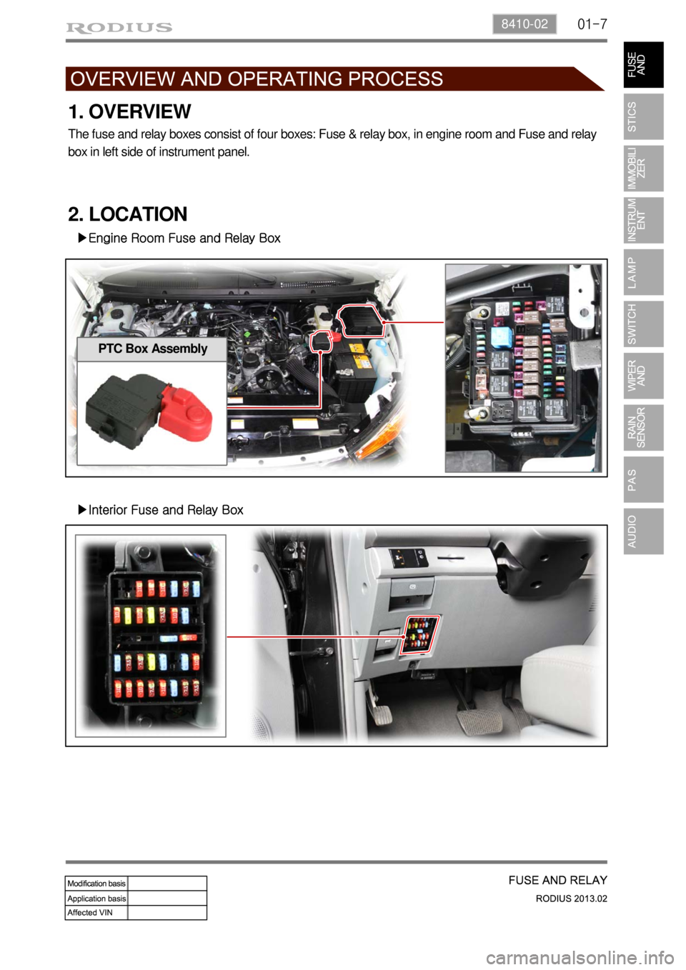
1. OVERVIEW
The fuse and relay boxes consist of four boxes: Fuse & relay box, in engine room and Fuse and relay
box in left side of instrument panel.
2. LOCATION
▶Engine Room Fuse and Relay Box
▶Interior Fuse and Relay Box
PTC Box Assembly
Page 503 of 796

06-38510-00
1. SPECIFICATIONS
1) Center Fascia Switch
Item Specifications
Center fascia switch &
bezel assemblyHazard warning flasher switch DC 12 V 10 A(lamp load)
Windshield heated glass switch
DC 12 V 1 A(inductive load) Rear heated glass switch
ESP OFF switch
Driver/front passenger seat warmer
switch
Fog lamp switch
2) 4WD Switch & HLLD Switch & Rear Wiper Operation Switch
Item Specifications
4WD switch &
HLLD switch &
rear wiper operation
switch assemblyWasher switch DC 12 V 3.8 A(lamp load)
Wiper switch DC 12 V 3.0 A (max. 10 A)
4WD switch DC 12 V 300 mA
HLLD switch DC 12 V 1 A (inductive load)
3) Steering Wheel Switch
Item Specifications
Steering wheel switch Rated voltage DC 5 V 0.1 A(rated load)
Operation temperature-30℃~+80℃
Page 505 of 796

06-58510-00
2. MAJOR CHANGES
Center fascia switch
- Design changed
Steering wheel switch assembly
- Power button deleted, steering wheel heating (option) switch added
- Design changed
Multifunction switch assembly
- Connector pin layout changed due to newly added steering wheel heating (option) circuit
- Contact coil and steering wheel angle sensor changed
Page 517 of 796

08-58610-11
2. RAIN SENSOR OPERATION
The rain sensor is installed on the specific heat treated windshield that has minimum 13% of
transmittance rate with specified intensity of radiation. It is installed on the glass with a adhesive of
Sorepa.
It communicates with STICS and makes the wipers to operate automatically under the rain sensing
mode (multifunction switch wiper: AUTO mode).
The emitting section of the rain sensor unit emits infrared rays against the windshield and then detects
the amount of rain drops by receiving reflected rays with photodiode.
The sensing section on the windshield is located just above the center point between LED and
photodiode.
Components and functions of the rain sensor unit
Unit latch
Rain
sensor unit
PCB assembly and
emitter lens
Emitter lens
The LED emits the infrared
rays is located at bottom and
the lens guides the infrared
rays to target point.
Receiver lens
The receiver lens guides the
reflected infrared rays from
windshield to photodiode.
Housing and
receiver lens
Housing and PCB
Rear
Front
Rain sensor unit (including cover)
Page 542 of 796

11-58910-05
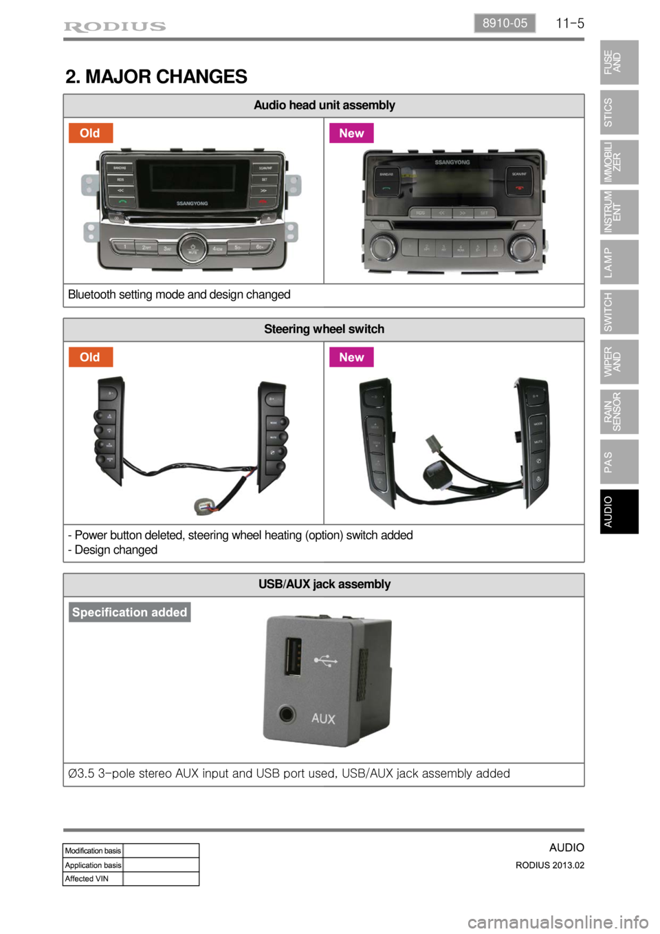
Audio head unit assembly
Bluetooth setting mode and design changed
Steering wheel switch
- Power button deleted, steering wheel heating (option) switch added
- Design changed
2. MAJOR CHANGES
USB/AUX jack assembly
Ø3.5 3-pole stereo AUX input and USB port used, USB/AUX jack assembly added
Page 545 of 796

11-8
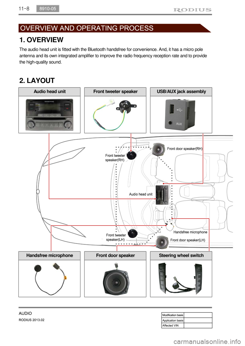
Front door speaker
2. LAYOUT
Handsfree microphoneSteering wheel switch
1. OVERVIEW
The audio head unit is fitted with the Bluetooth handsfree for convenience. And, it has a micro pole
antenna and its own integrated amplifier to improve the radio frequency reception rate and to provide
the high-quality sound.
Audio head unitFront tweeter speakerUSB/AUX jack assembly