SSANGYONG TURISMO 2013 Workshop Manual
TURISMO 2013
SSANGYONG
SSANGYONG
https://www.carmanualsonline.info/img/67/57526/w960_57526-0.png
SSANGYONG TURISMO 2013 Workshop Manual
Page 623 of 796
07-8
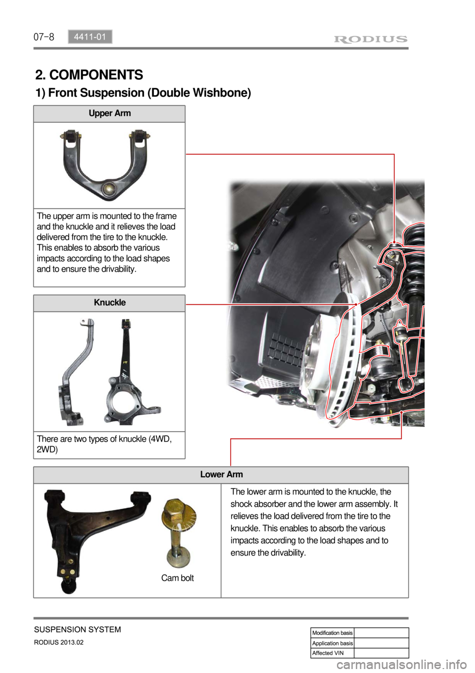
Upper Arm
The upper arm is mounted to the frame
and the knuckle and it relieves the load
delivered from the tire to the knuckle.
This enables to absorb the various
impacts according to the load shapes
and to ensure the drivability.
Lower Arm
Knuckle
There are two types of knuckle (4WD,
2WD)
Cam bolt
1) Front Suspension (Double Wishbone)
The lower arm is mounted to the knuckle, the
shock absorber and the lower arm assembly. It
relieves the load delivered from the tire to the
knuckle. This enables to absorb the various
impacts according to the load shapes and to
ensure the drivability.
2. COMPONENTS
Page 624 of 796
07-94411-01
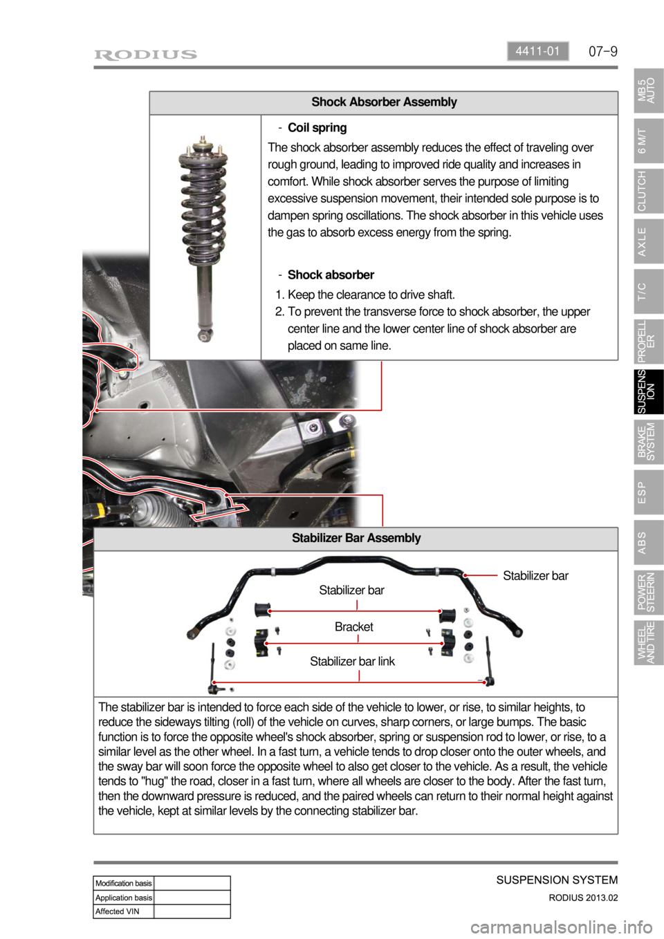
Shock Absorber Assembly
Stabilizer Bar Assembly
The stabilizer bar is intended to force each side of the vehicle to lower, or rise, to similar heights, to
reduce the sideways tilting (roll) of the vehicle on curves, sharp corners, or large bumps. The basic
function is to force the opposite wheel's shock absorber, spring or suspension rod to lower, or rise, to a
similar level as the other wheel. In a fast turn, a vehicle tends to drop closer onto the outer wheels, and
the sway bar will soon force the opposite wheel to also get closer to the vehicle. As a result, the vehicle
tends to "hug" the road, closer in a fast turn, where all wheels are closer to the body. After the fast turn,
then the downward pressure is reduced, and the paired wheels can return to their normal height against
the vehicle, kept at similar levels by the connecting stabilizer bar.
Stabilizer bar
Stabilizer bar
Bracket
Stabilizer bar link
Coil spring -
The shock absorber assembly reduces the effect of traveling over
rough ground, leading to improved ride quality and increases in
comfort. While shock absorber serves the purpose of limiting
excessive suspension movement, their intended sole purpose is to
dampen spring oscillations. The shock absorber in this vehicle uses
the gas to absorb excess energy from the spring.
Shock absorber -
Keep the clearance to drive shaft.
To prevent the transverse force to shock absorber, the upper
center line and the lower center line of shock absorber are
placed on same line. 1.
2.
Page 625 of 796
07-10
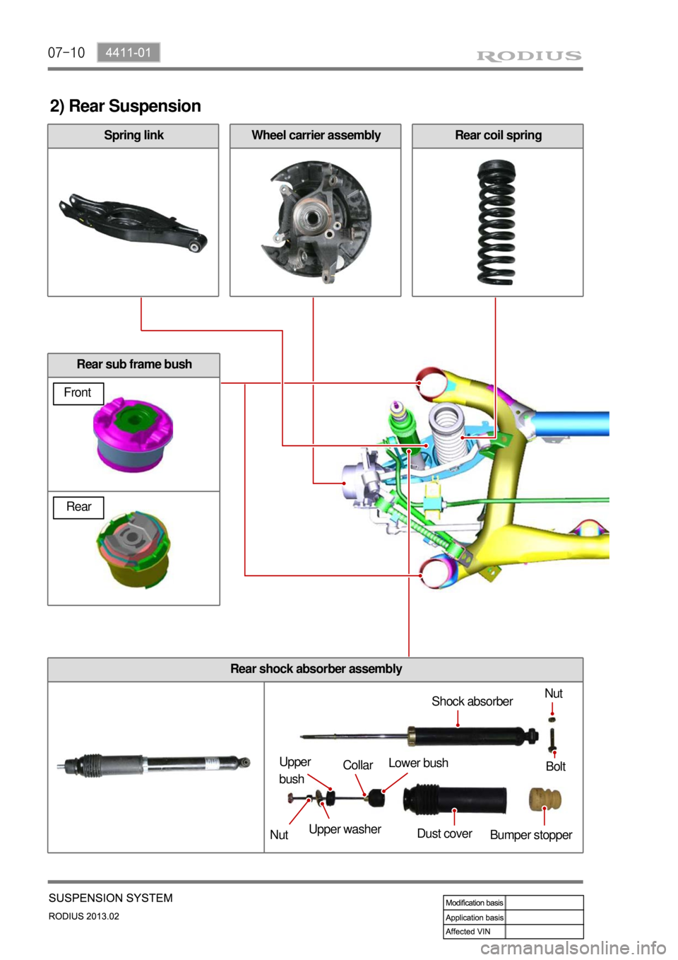
Spring link
2) Rear Suspension
Rear coil springWheel carrier assembly
Rear sub frame bush
Nut
Upper washer Upper
bush
Bumper stopper Lower bush
Dust coverShock absorber
Bolt
NutCollar
Front
Rear
Rear shock absorber assembly
Page 626 of 796
07-114411-01
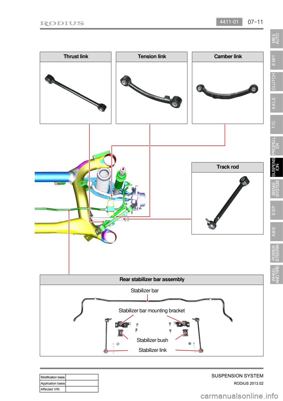
Thrust linkCamber linkTension link
Track rod
Rear stabilizer bar assembly
Stabilizer bar
Stabilizer bar mounting bracket
Stabilizer bush
Stabilizer link
Page 631 of 796
08-4
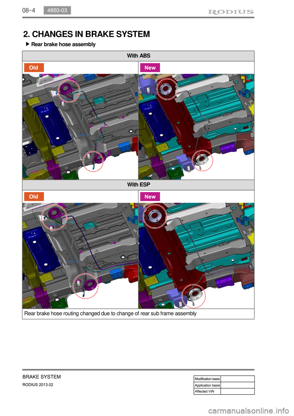
2. CHANGES IN BRAKE SYSTEM
Rear brake hose assembly ▶
With ABS
With ESP
Rear brake hose routing changed due to change of rear sub frame assembly
Page 635 of 796
08-8
Problem Cause Action
Burning smell
around tireToo frequent braking in high driving speed Reduce the use of
foot brake/use
engine brake
properly Use only foot brake during downhill driving
Driving with foot on brake pedal Get off the foot from
pedal
Foreign materials such as dirt or sand in brake system Replace: caliper,
wheel cylinder,
master cylinder,
return spring
Broken return spring in shoe assembly Replace
Incorrectly adjusted parking brake cable Adjust
Incorrect wheel or wheel cover
(generating the heat)Replace
Page 641 of 796
08-14
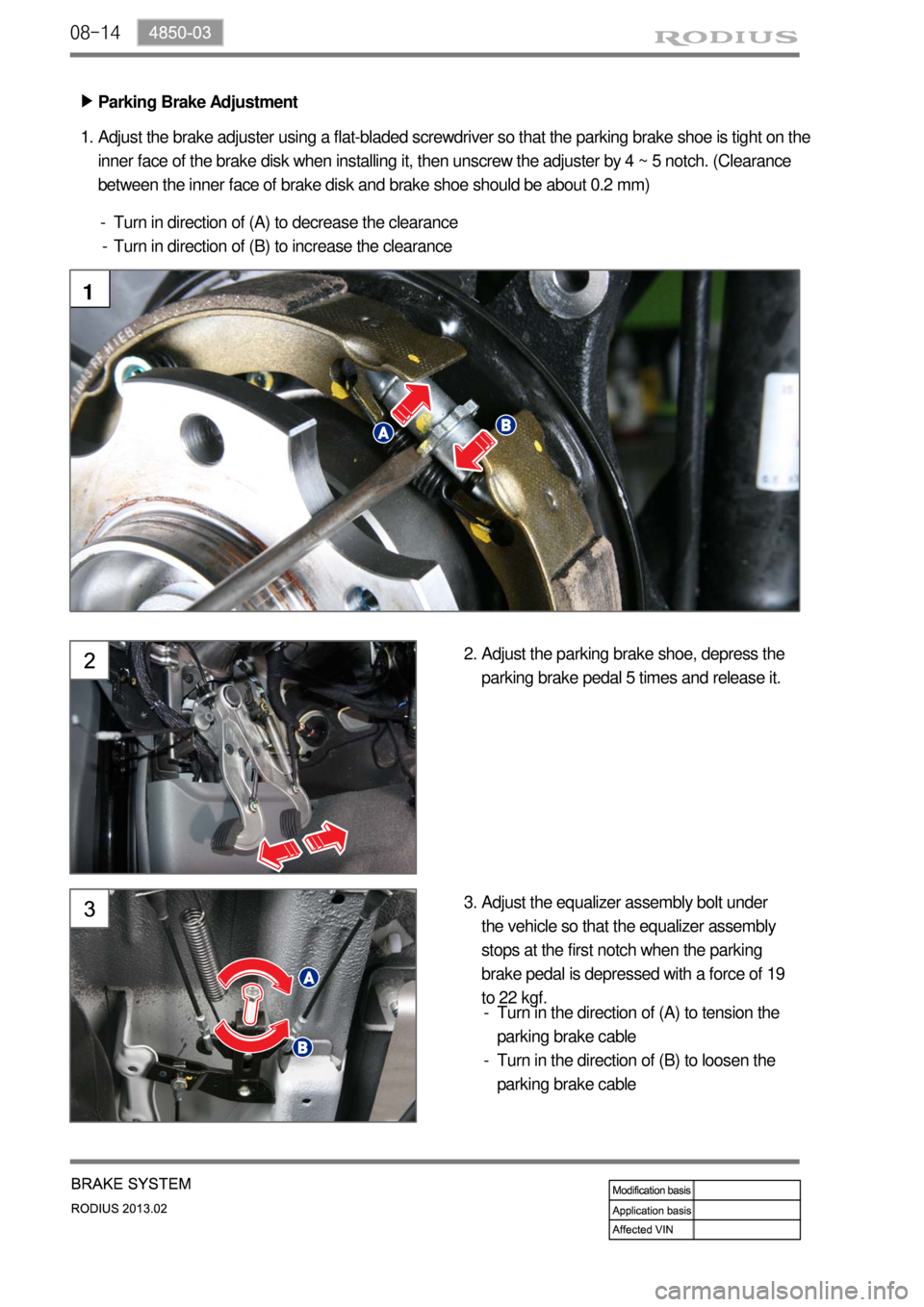
Parking Brake Adjustment ▶
Adjust the brake adjuster using a flat-bladed screwdriver so that the parking brake shoe is tight on the
inner face of the brake disk when installing it, then unscrew the adjuster by 4 ~ 5 notch. (Clearance
between the inner face of brake disk and brake shoe should be about 0.2 mm) 1.
Turn in direction of (A) to decrease the clearance
Turn in direction of (B) to increase the clearance -
-
1
Adjust the parking brake shoe, depress the
parking brake pedal 5 times and release it. 2.
Adjust the equalizer assembly bolt under
the vehicle so that the equalizer assembly
stops at the first notch when the parking
brake pedal is depressed with a force of 19
to 22 kgf. 3.
Turn in the direction of (A) to tension the
parking brake cable
Turn in the direction of (B) to loosen the
parking brake cable -
-
Page 644 of 796
08-174850-03
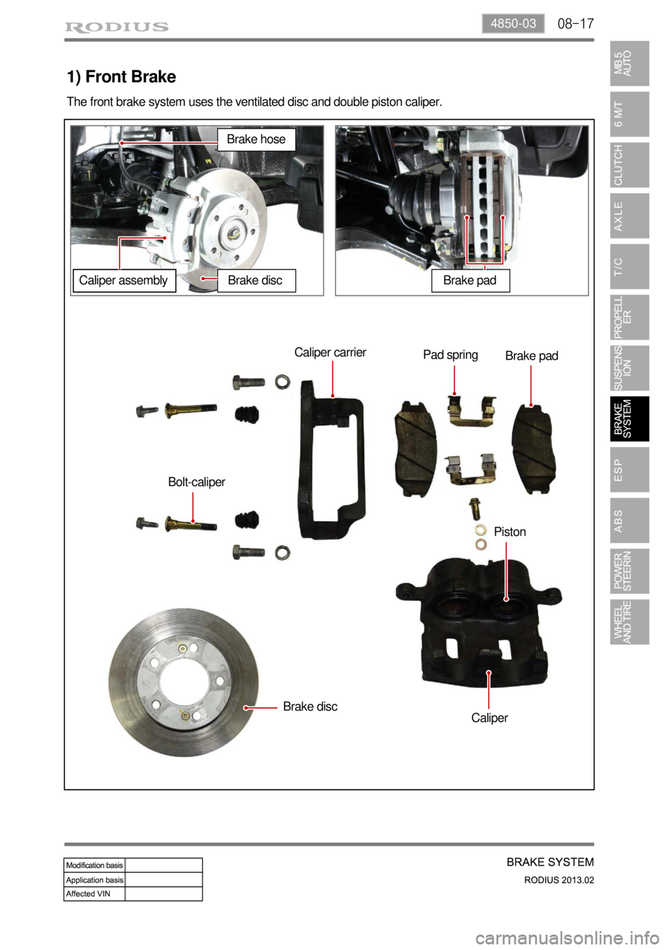
1) Front Brake
The front brake system uses the ventilated disc and double piston caliper.
Caliper carrier
Pad spring
Brake pad
Bolt-caliper
Brake disc
CaliperPiston
Brake hose
Caliper assemblyBrake discBrake pad
Page 646 of 796
08-194850-03
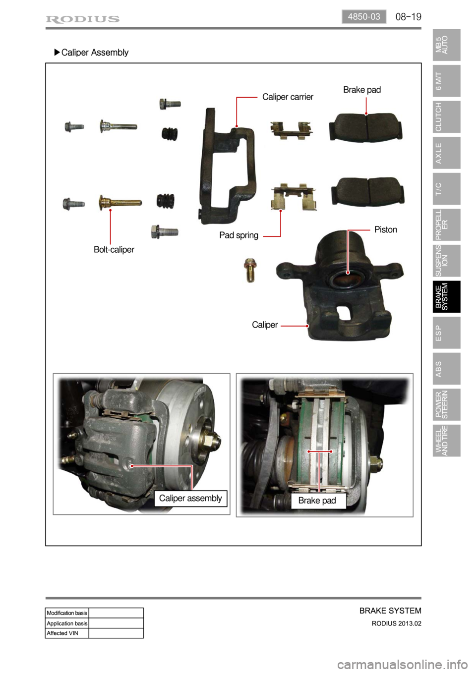
▶Caliper Assembly
Bolt-caliper
CaliperPiston
Pad springCaliper carrierBrake pad
Caliper assembly
Brake pad
Page 647 of 796
08-20
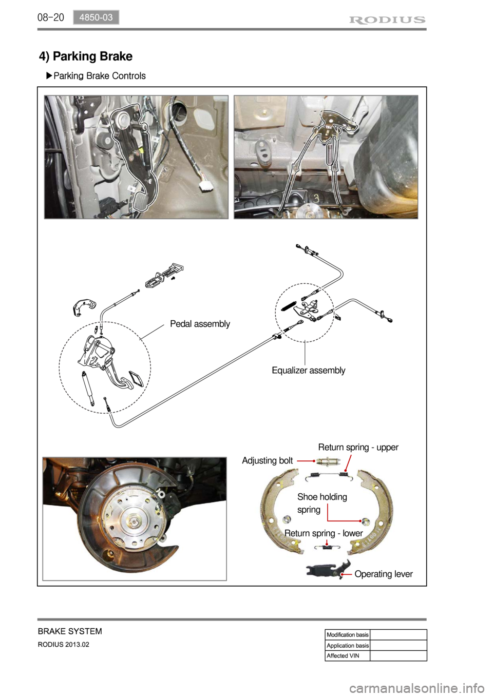
4) Parking Brake
▶Parking Brake Controls
Operating lever
Return spring - lowerShoe holding
springReturn spring - upper
Adjusting bolt
Pedal assembly
Equalizer assembly
