lock SSANGYONG TURISMO 2013 Owner's Manual
[x] Cancel search | Manufacturer: SSANGYONG, Model Year: 2013, Model line: TURISMO, Model: SSANGYONG TURISMO 2013Pages: 796, PDF Size: 78.99 MB
Page 284 of 796
09-8
(3) Starting with jumper cable
If the battery is weak or terminated, the battery from another vehicle can be used with jumper
cables to start the engine.
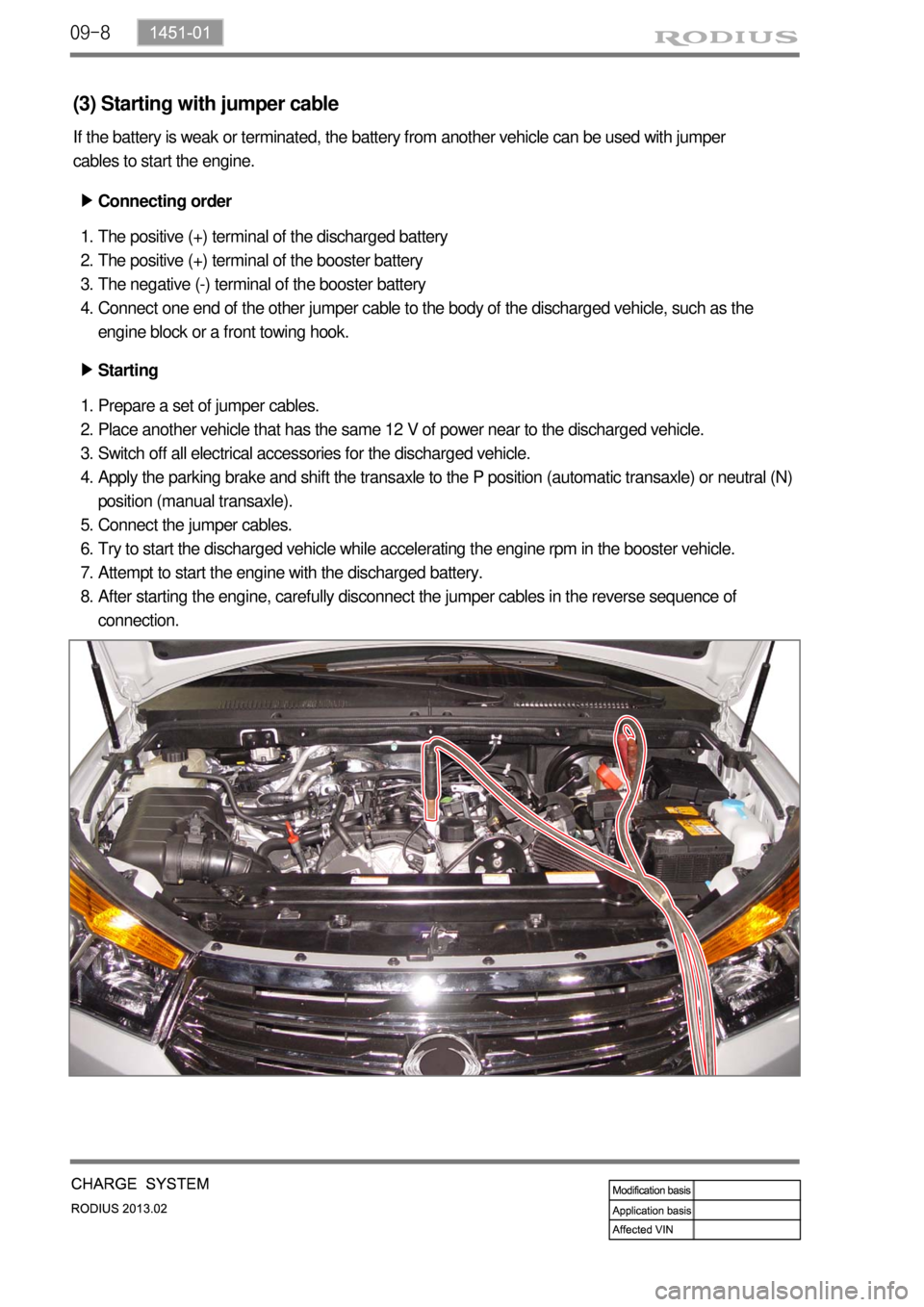
Connecting order ▶
The positive (+) terminal of the discharged battery
The positive (+) terminal of the booster battery
The negative (-) terminal of the booster battery
Connect one end of the other jumper cable to the body of the discharged vehicle, such as the
engine block or a front towing hook. 1.
2.
3.
4.
Starting ▶
Prepare a set of jumper cables.
Place another vehicle that has the same 12 V of power near to the discharged vehicle.
Switch off all electrical accessories for the discharged vehicle.
Apply the parking brake and shift the transaxle to the P position (automatic transaxle) or neutral (N)
position (manual transaxle).
Connect the jumper cables.
Try to start the discharged vehicle while accelerating the engine rpm in the booster vehicle.
Attempt to start the engine with the discharged battery.
After starting the engine, carefully disconnect the jumper cables in the reverse sequence of
connection. 1.
2.
3.
4.
5.
6.
7.
8.
Page 298 of 796

11-31461-01
1. SPECIFICATION
Description Specification
Capacity 12V 2.3kW
Engagement Meshed type
Rotating direction Clockwise
Pinion gear manufacturing Cooled forging
Solenoid operating voltage Max. 8 V
Weight 2.5 kg
Bracket manufacturing Aluminum die casting
Page 336 of 796

15-8
2. SYSTEM OPERATION
1) Input/Output of ECU
(1) ECU Block diagram
Page 352 of 796
15-24
(8) Swirl control
A. Overview
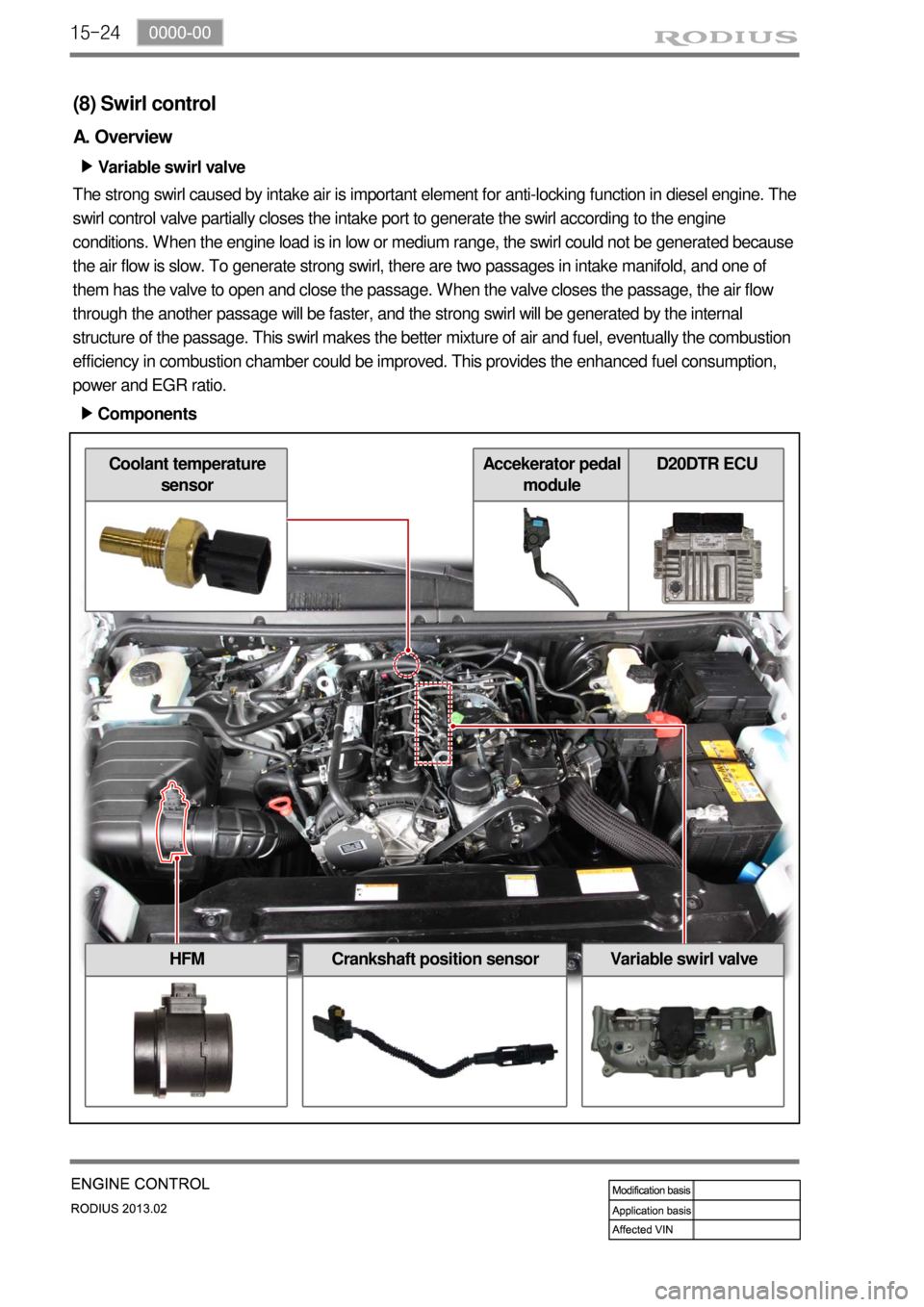
Variable swirl valve ▶
The strong swirl caused by intake air is important element for anti-locking function in diesel engine. The
swirl control valve partially closes the intake port to generate the swirl according to the engine
conditions. When the engine load is in low or medium range, the swirl could not be generated because
the air flow is slow. To generate strong swirl, there are two passages in intake manifold, and one of
them has the valve to open and close the passage. When the valve closes the passage, the air flow
through the another passage will be faster, and the strong swirl will be generated by the internal
structure of the passage. This swirl makes the better mixture of air and fuel, eventually the combustion
efficiency in combustion chamber could be improved. This provides the enhanced fuel consumption,
power and EGR ratio.
Components ▶
HFMCrankshaft position sensorVariable swirl valve
Coolant temperature
sensorAccekerator pedal
moduleD20DTR ECU
Page 366 of 796
15-38
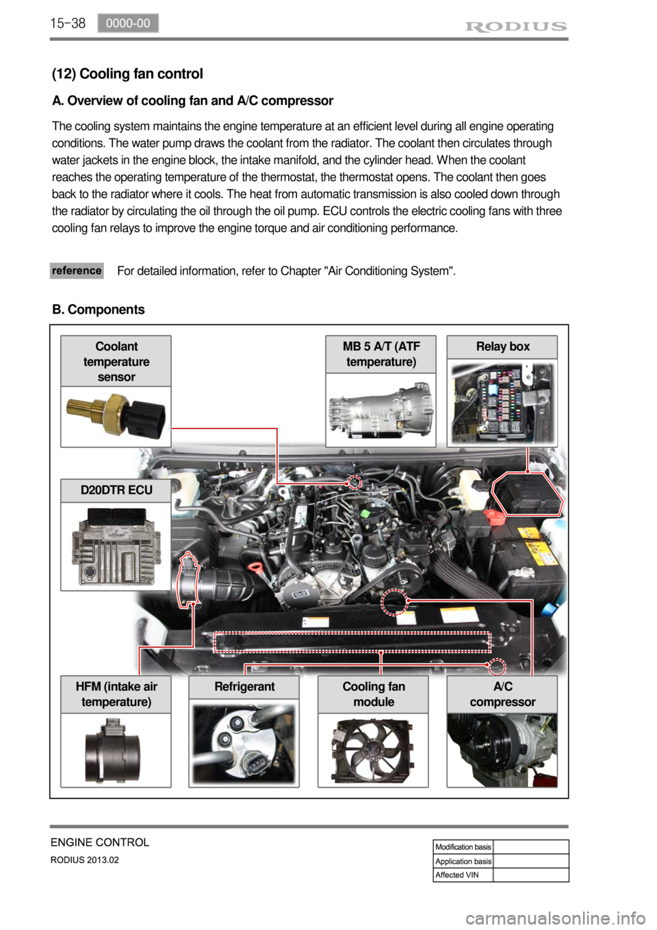
Relay box
A/C
compressorHFM (intake air
temperature)Cooling fan
module
MB 5 A/T (ATF
temperature)Coolant
temperature
sensor
(12) Cooling fan control
A. Overview of cooling fan and A/C compressor
The cooling system maintains the engine temperature at an efficient level during all engine operating
conditions. The water pump draws the coolant from the radiator. The coolant then circulates through
water jackets in the engine block, the intake manifold, and the cylinder head. When the coolant
reaches the operating temperature of the thermostat, the thermostat opens. The coolant then goes
back to the radiator where it cools. The heat from automatic transmission is also cooled down through
the radiator by circulating the oil through the oil pump. ECU controls the electric cooling fans with three
cooling fan relays to improve the engine torque and air conditioning performance.
For detailed information, refer to Chapter "Air Conditioning System".
B. Components
D20DTR ECU
Refrigerant
Page 377 of 796
15-490000-00
E. Cautions
Use only specified Engine Oil (approved by MB Sheet 229.51) for CDPF. -
Use only specified engine oil (Low Ash Oil) ▶
The vehicle equipped with CDPF should use specific engine oil to improve the engine
performance and fuel economy, and ensure the service life of CDPF. -
Issue with normal engine oil ▶
Sulfur, one of the contents of engine oil is burned and generates soot that is not regenerated by
the DPF. This remains on the filter as ashes and keeps accumulating. Eventually, this ashes will
block the filter. -
Benefit for specified engine oil ▶
Minimized the sulfur content of engine oil which reduces the service life.
Improved fuel economy and emission level of CO2 with high performance and low viscosity.
Increased service life of engine oil with high resistance to temperature. -
-
-
Problems when using unspecified engine oil ▶
The service life of filter may be reduced by 30% or more by the ashes accumulated on the filter.
The fuel economy may be reduced because of engine rolling resistance, frequent regeneration of
DPF. -
-
These problems are also caused by oil with high sulfur content, such as tax exemption oil and
heating oil, etc. *
Page 382 of 796

01-70000-00
2. DESCRIPTION AND OPERATION
1) Cleanliness and Care
An automobile engine is a combination of many machined, honed, polished and lapped surfaces with
tolerances that are measured in the ten-thousandths of an inch. When any internal engine parts are
serviced, care and cleanliness are important. A liberal coating of engine oil should be applied to friction
areas during assembly, to protect and lubricate the surfaces on initial operation.
Proper cleaning and protection of machined surfaces and friction areas is part of the repair procedure.
This is considered standard shop practice even if not specifically stated.
Whenever valve train components are removed for service, they should be kept in order.
They should be installed in the same locations, and with the same mating surfaces, as when they were
removed. Battery cables should be disconnected before any major work is performed on the engine.
Failure to disconnect cables may result in damage to wire harness or other electrical parts.
2) On-Engine Service
Disconnect the negative battery cable before removing or installing any electrical unit, or when a
tool or equipment could easily come in contact with exposed electrical terminals.
Disconnecting this cable will help prevent personal injury and damage to the vehicle.
The ignition must also be in LOCK unless otherwise noted.
Notice Any time the air cleaner is removed, the intake opening -
Any time the air cleaner is removed, the intake opening should be covered. This will protect
against accidental entrance of foreign material, which could follow the intake passage into the
cylinder and cause extensive damage when the engine is started. -
Page 398 of 796
07-6
1. GENERAL DESCRIPTION
The cooling system maintains the engine temperature at an efficient level during all engine operating
conditions. When the engine is cold, the cooling system cools the engine slowly or not at all. This slo
w
cooling of the engine allows the engine to warm up quickly. The cooling system includes a radiator and
recovery subsystem, cooling fans, a thermostat and housing, a water pump, and a water pump drive
belt. The timing belt drives the water pump. All components must function properly for the cooling
system to operation. The water pump draws the coolant from the radiator.
The coolant then circulates through water jackets in the engine block, the intake manifold, and the
cylinder head. When the coolant reaches the operating temperature of the thermostat, the thermostat
opens. The coolant then goes back to the radiator where it cools. This system directs some coolant
through the hoses to the heat core. This provides for heating and defrosting. The coolant reservoir is
connected to the radiator to recover the coolant displaced by expansion from the high temperatures.
The coolant reservoir maintains the correct coolant level. The cooling system for this vehicle has no
radiator cap or filler neck. The coolant is added to the cooling system through the coolant reservoir.
Page 417 of 796
01-4
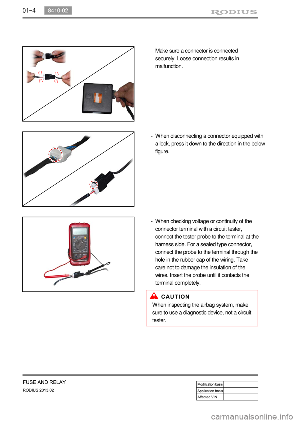
Make sure a connector is connected
securely. Loose connection results in
malfunction. -
When inspecting the airbag system, make
sure to use a diagnostic device, not a circuit
tester.When disconnecting a connector equipped with
a lock, press it down to the direction in the below
figure. -
When checking voltage or continuity of the
connector terminal with a circuit tester,
connect the tester probe to the terminal at the
harness side. For a sealed type connector,
connect the probe to the terminal through the
hole in the rubber cap of the wiring. Take
care not to damage the insulation of the
wires. Insert the probe until it contacts the
terminal completely. -
Page 449 of 796

02-18
This function does not work if the vehicle speed is over 3 km/h.
The system outputs “UNLOCK” for 5 seconds (T2) from 0.5 seconds after the driver’s door
is opened and the door lock switch is changed to “LOCK” (while the ignition key is in ignition
switch).
The system outputs “UNLOCK” for 5 seconds (T2) when the door lock switch is changed to
“LOCK” from “UNLOCK” and the driver’s door is closed within 0.5 seconds (T1) (while the
ignition key is in ignition switch). 1.
2.
3. ▶Key Reminder
Operating conditions for (*1) and (*2) -
(*1): Driver’s door is opened and driver’s door lock switch is turned to LOCK
(*2): Passenger’s door is opened and passenger’s door lock switch is turned to LOCK