torque SSANGYONG TURISMO 2013 Owner's Manual
[x] Cancel search | Manufacturer: SSANGYONG, Model Year: 2013, Model line: TURISMO, Model: SSANGYONG TURISMO 2013Pages: 796, PDF Size: 78.99 MB
Page 346 of 796

15-18
C. Idle Speed Controller
The idle speed controller consists of 2 principal modules:
The first module determines the required idle speed according to:
* The operating conditions of the engine (coolant temperature, gear engaged)
* Any activation of the electrical consumers (power steering, air conditioning, others)
* The battery voltage
* The presence of any faults liable to interface with the rail pressure control or the injection control.
In this case, increase the idle speed to prevent the engine from stalling.
The second module is responsible for providing closed loop control of the engine's idle speed by
adapting the minimum fuel according to the difference between the required idle speed and the
engine speed. -
-
D. Flow Limitation
The flow limitation strategy is based on the following strategies:
The flow limitation depending on the filling of the engine with air is determined according to the
engine speed and the air flow. This limitation allows smoke emissions to be reduced during
stabilized running.
The flow limitation depending on the atmospheric pressure is determined according to the
engine speed and the atmospheric pressure. It allows smoke emissions to be reduced when
driving at altitude.
The full load flow curve is determined according to the gear engaged and the engine speed. It
allows the maximum torque delivered by the engine to be limited.
A performance limitation is introduced if faults liable to upset the rail pressure control or the
injection control are detected by the system. In this case, and depending on the gravity of the
fault, the system activates: -
-
-
-
Reduced fuel logic 1: Guarantees 75 % of the performance without limiting the engine speed.
Reduced fuel logic 2: Guarantees 50 % of the performance with the engine speed limited to
3,000 rpm.
Reduce fuel logic 3: Limits the engine speed to 2,000 rpm.
The system chooses the lowest of all values.
A correction depending on the coolant temperature is added to the flow limitation. This correction
makes it possible to reduce the mechanical stresses while the engine is warming up.
The correction is determined according to the coolant temperature, the engine speed and the time
which has passed since starting.
E. Superchager Flow Demand
The supercharge flow is calculated according to the engine speed and the coolant temperature. A
correction depending on the air temperature and the atmospheric pressure is made in order to
increase the supercharge flow during cold starts. It is possible to alter the supercharge flow value by
adding a flow offset with the aid of the diagnostic tool
Page 366 of 796

15-38
Relay box
A/C
compressorHFM (intake air
temperature)Cooling fan
module
MB 5 A/T (ATF
temperature)Coolant
temperature
sensor
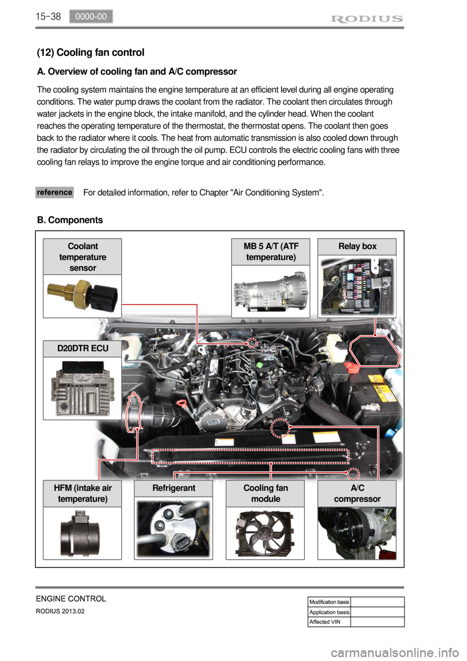
(12) Cooling fan control
A. Overview of cooling fan and A/C compressor
The cooling system maintains the engine temperature at an efficient level during all engine operating
conditions. The water pump draws the coolant from the radiator. The coolant then circulates through
water jackets in the engine block, the intake manifold, and the cylinder head. When the coolant
reaches the operating temperature of the thermostat, the thermostat opens. The coolant then goes
back to the radiator where it cools. The heat from automatic transmission is also cooled down through
the radiator by circulating the oil through the oil pump. ECU controls the electric cooling fans with three
cooling fan relays to improve the engine torque and air conditioning performance.
For detailed information, refer to Chapter "Air Conditioning System".
B. Components
D20DTR ECU
Refrigerant
Page 554 of 796

01-33650-01
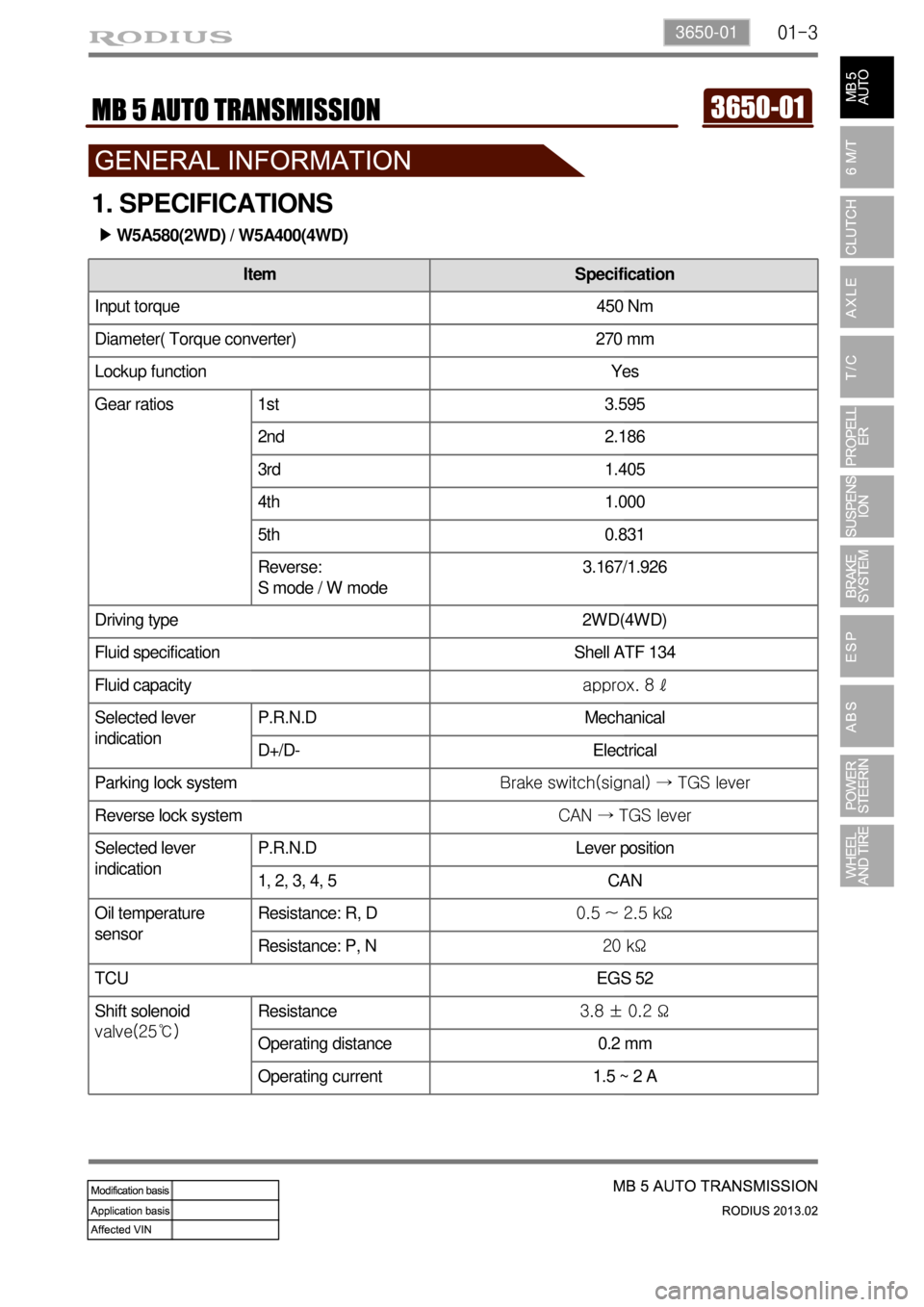
Diameter( Torque converter) 270 mm
Lockup function Yes
Gear ratios 1st 3.595
2nd 2.186
3rd 1.405
4th 1.000
5th 0.831
Reverse:
S mode / W mode3.167/1.926
Driving type 2WD(4WD)
Fluid specification Shell ATF 134
Fluid capacityapprox. 8 ℓ
Selected lever
indicationP.R.N.D Mechanical
D+/D- Electrical
Parking lock systemBrake switch(signal) → TGS lever
Reverse lock systemCAN → TGS lever
Selected lever
indicationP.R.N.D Lever position
1, 2, 3, 4, 5 CAN
Oil temperature
sensorResistance: R, D0.5 ~ 2.5 kΩ
Resistance: P, N20 kΩ
TCU EGS 52
Shift solenoid
valve(25℃)Resistance3.8 ± 0.2 Ω
Operating distance 0.2 mm
Operating current 1.5 ~ 2 A
Item Specification
Input torque 450 Nm
1. SPECIFICATIONS
W5A580(2WD) / W5A400(4WD) ▶
Page 557 of 796

01-6
3. TIGHTENING TORQUE
Description Tightening Torque (Nm) Remark
Oil drain plug (oil pan) 14 Hexagon, 5 mm
Oil filler pipe (upper) 8 ~ 10 -
Oil filler pipe (lower) 8 ~ 10 -
Oil cooler pipe 30 ~ 38 -
Oil pan 8 T 30
Torque converter housing/oil pump 20 -
Transmission rear mounting bracket
(left/right)36 ~ 44 -
Transmission rear mounting bracket
(center)20 -
Torque converter mounting bolt 42 -
Converter housing/engine 75 ~ 90 -
Converter housing/transmission housing 20 T 45
Valve bod
y8T 30
Valve body side cover 4 T 30
Solenoid valve 8 -
12-point collar nut 200 12-point, 30 mm
B2 housing bolt 16 T 45
Selector lever unit mounting bolt 6 -
Page 559 of 796

01-8
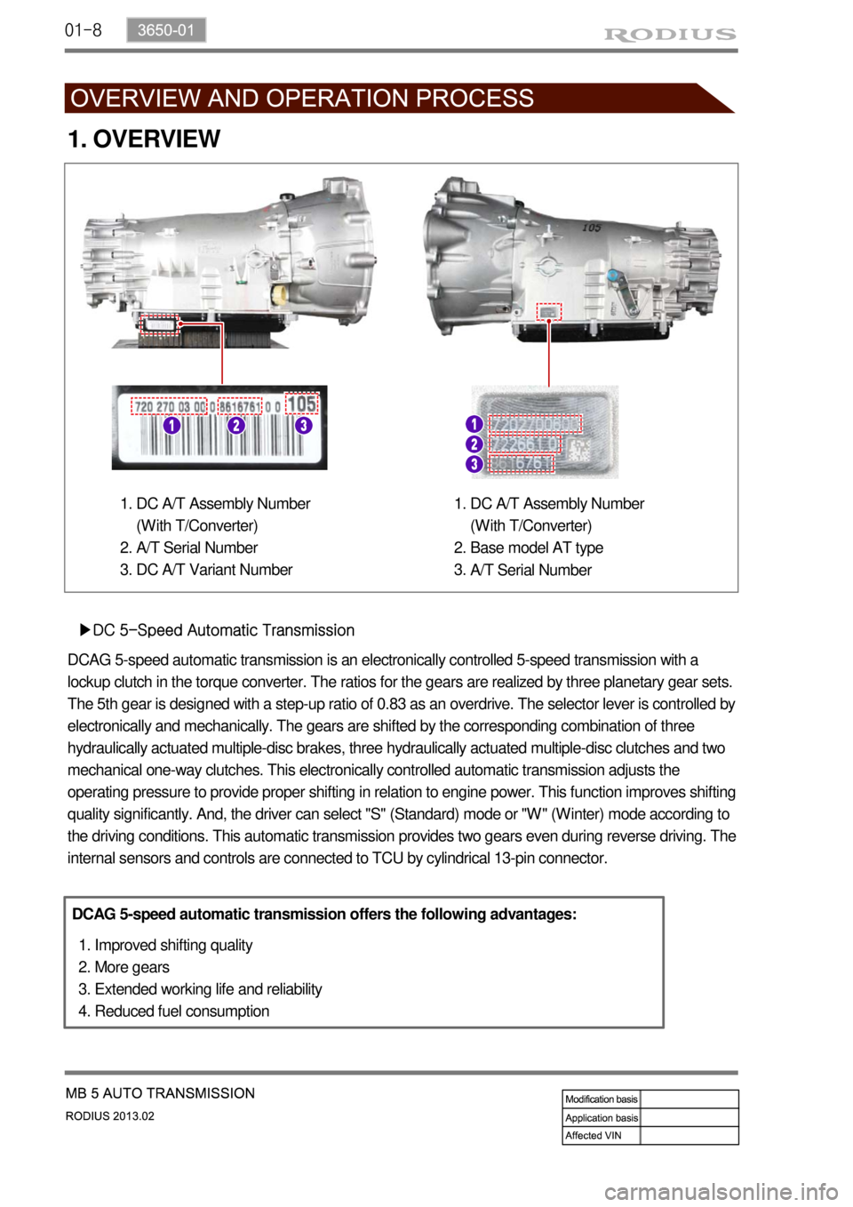
1. OVERVIEW
▶DC 5-Speed Automatic Transmission
DCAG 5-speed automatic transmission is an electronically controlled 5-speed transmission with a
lockup clutch in the torque converter. The ratios for the gears are realized by three planetary gear sets.
The 5th gear is designed with a step-up ratio of 0.83 as an overdrive. The selector lever is controlled by
electronically and mechanically. The gears are shifted by the corresponding combination of three
hydraulically actuated multiple-disc brakes, three hydraulically actuated multiple-disc clutches and two
mechanical one-way clutches. This electronically controlled automatic transmission adjusts the
operating pressure to provide proper shifting in relation to engine power. This function improves shifting
quality significantly. And, the driver can select "S" (Standard) mode or "W" (Winter) mode according to
the driving conditions. This automatic transmission provides two gears even during reverse driving. The
internal sensors and controls are connected to TCU by cylindrical 13-pin connector.
DCAG 5-speed automatic transmission offers the following advantages:
Improved shifting quality
More gears
Extended working life and reliability
Reduced fuel consumption 1.
2.
3.
4.
DC A/T Assembly Number
(With T/Converter)
A/T Serial Number
DC A/T Variant Number 1.
2.
3.DC A/T Assembly Number
(With T/Converter)
Base model AT type
A/T Serial Number 1.
2.
3.
Page 562 of 796

01-113650-01
▶1st Gear (3.932)
Torque converter lockup clutch
Engine speed
Transmission, input shaft
1st gear ratio
2nd gear ratio 16.
A.
B.
C.
D. 3rd gear ratio
Mounting elements
Rear planetary gear set
Stator E.
F.
H.
L.Center planetary gear set
Impeller
Turbine wheel
Front planetary gear set M.
P.
T.
V.
Input shaft: Clockwise rotation
Front sun gear: Locked by F1 and B1, Planetary gear carrier: Rotation with reduced speed
Rear ring gear: Counterclockwise rotation
Rear sun gear: Locked by F2 and B2, Planetary gear carrier: Clockwise rotation with reduced
speed
Center ring gear: Clockwise rotation
Center sun gear: Locked by B2, Rotation with reduced speed
Output shaft: Clockwise rotation -
-
-
-
-
-
-
Gear C1 C2 C3 B1 B2 B3 F1 F2 Lockup clutch
1● ● ● ● ●
3) 3)
3) Overrun
Page 563 of 796

01-12
▶2nd Gear (2.408)
Torque converter lockup clutch
Engine speed
Transmission, input shaft
1st gear ratio 16.
A.
B.
C.2nd gear ratio
Mounting elements
Rear planetary gear set
Stator D.
E.
H.
L.Center planetary gear set
Impeller
Turbine wheel
Front planetary gear set M.
P.
T.
V.
Input shaft: Clockwise rotation
Sun gear and planetary gear carrier: Clockwise rotation by C1 activation
Rear ring gear: Clockwise rotation
Rear sun gear: Locked by F2 and B2, Planetary gear carrier: Rotation with reduced speed
Center ring gear: Clockwise rotation
Sun gear: Locked by B2, Planetary gear carrier: Rotation with reduced speed
Output shaft: Clockwise rotation -
-
-
-
-
-
-
Gear C1 C2 C3 B1 B2 B3 F1 F2
2 ● ● ● ●
3)
3) Overrun
Page 564 of 796

01-133650-01
▶3rd Gear (1.486)
Torque converter lockup clutch
Engine speed
Transmission, input shaft
1st gear ratio 16.
A.
B.
C.Mounting elements
Rear planetary gear set
Stator
Center planetary gear set D.
H.
L.
M.Impeller
Turbine wheel
Front planetary gear set P.
T.
V.
Input shaft: Clockwise rotation
Front ring gear: Clockwise rotation
Center ring gear: Clockwise rotation by clutch 2 activation (direct connection)
Center sun gear: Locked by B2, Planetary gear carrier: Clockwise rotation with reduced
speed
Output shaft: Clockwise rotation -
-
-
-
-
Gear C1 C2 C3 B1 B2 B3 F1 F2
3 ● ● ●
Page 565 of 796

01-14
▶4th Gear (1.000)
Torque converter lockup clutch
Engine speed
Planetary gear set 16.
A.
B. Stator
Center planetary gear set
Impeller L.
M.
P.Turbine wheel
Front planetary gear
set T.
V.
Input shaft: Clockwise rotation
Front ring gear: Clockwise rotation
Center ring gear and rear planetary gear carrier: Clockwise rotation
Front sun gear and planetary gear carrier: Clockwise rotation (direct connection)
Rear ring gear: Clockwise rotation
Rear sun gear: Rotation by ring gear and planetary gear carrier (direct connection)
Center ring gear: Clockwise rotation by C3 activation
Planetary gear carrier: Clockwise rotation by center sun gear and ring gear (direct
connection)
Output shaft: Clockwise rotation -
-
-
-
-
-
-
-
-
Gear C1 C2 C3 B1 B2 B3 F1 F2
4 ● ● ●
Page 566 of 796

01-153650-01
▶5th Gear (0.830)
Torque converter lockup clutch
Engine speed
Transmission, input shaft
1st gear ratio 16.
A.
B.
C.
D.2nd gear ratio
3rd gear ratio
Mounting elements
Rear planetary gear set
Stator E.
F.
H.
L.Center planetary gear set
Impeller
Turbine wheel
Front planetary gear set M.
P.
T.
V
Input shaft: Clockwise rotation
Front sun gear: Locked, Planetary gear carrier: Rotation with reduced speed
Rear planetary gear carrier: Clockwise rotation with reduced speed
Center ring gear and rear planetary gear carrier: Clockwise rotation by clutch C2 activation
Rear sun gear: Clockwise rotation because rear planetary gear carrier rotates faster than
rear ring gear (increased speed)
Center sun gear: Clockwise rotation with increased speed by C3 activation
Center planetary gear carrier: Clockwise rotation (increased speed)
Output shaft: Clockwise rotation (increased speed) -
-
-
-
-
-
-
-
Gear C1 C2 C3 B1 B2 B3 F1 F2
5 ● ● ● ●
3)
3) Overrun