Passenger light SUBARU CROSSTREK 2017 1.G Owner's Guide
[x] Cancel search | Manufacturer: SUBARU, Model Year: 2017, Model line: CROSSTREK, Model: SUBARU CROSSTREK 2017 1.GPages: 572, PDF Size: 41.52 MB
Page 237 of 572
This setting can be changed by a
SUBARU dealer. Consult your SUBARU
dealer for details.
CAUTION
Do not attach anything that disturbs
the rear wiper operation on the rear
gate. Doing so may damage the rear
wiper when it operates.
!Washer
To wash the rear window while the rear
wiper is operating, turn the knob switch
upward to the“
”position. The washer
fluid sprays until you release the knob.
To wash the rear window when the rear
wiper is not in use, turn the knob switch
downward to the“
”position. The washer
fluid sprays and the wiper operates until
you release the knob.
Mirrors
Always check that the inside and outside
mirrors are properly adjusted before you
start driving.
&Inside mirror
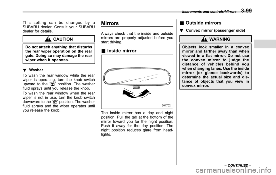
The inside mirror has a day and night
position. Pull the tab at the bottom of the
mirror toward you for the night position.
Push it away for the day position. The
night position reduces glare from head-
lights.
&Outside mirrors
!Convex mirror (passenger side)
WARNING
Objects look smaller in a convex
mirror and farther away than when
viewed in a flat mirror. Do not use
the convex mirror to judge the
distance of vehicles behind you
when changing lanes. Use the inside
mirror (or glance backwards) to
determine the actual size and dis-
tance of objects that you view in
convex mirror.
Instruments and controls/Mirrors
–CONTINUED–3-99
Page 250 of 572
Climate control/Manual climate control operation
!“DUAL”mode (type D)
You can change the setting of the driver’s
side and front passenger’s side tempera-
ture independently by selecting the
“DUAL”mode.
You can select the“DUAL”mode by
performing either of the following proce-
dures.
.Press the“DUAL”button
.Turn the passenger’s side temperature
control dial
The“DUAL”mode can be canceled by
pressing the“DUAL”button.
When the“DUAL”mode is selected:
Turn the driver’ssidedialtosetthe
driver’s side temperature. Turn the front
passenger’ssidedialtosetthefront
passenger’s side temperature.
When the“DUAL”mode is canceled:
Set the desired temperature by turning the
driver’s side dial.
&Fan speed control
The fan operates only when the ignition
switch is in the“ON”position. Select the
preferred fan speed by turning the fan
speed control dial.
&Air conditioner control
The air conditioner operates only when
the engine is running.
Press the air conditioner button while the
fan is in operation to turn on the air
conditioner. When the air conditioner is
on, the“A/C”indicator light illuminates.
To turn off the air conditioner, press the
button again.
NOTE
For efficient defogging or dehumidify-
ing in cold weather, turn on the air
conditioner. However, if the ambient
temperature decreases to approxi-
mately 328F(08C), the air conditioner
compressor will stop operating.
&Air inlet selection
Select the air inlet by pressing the air inlet
selection button.
ON position (recirculation):Interior air is
recirculated inside the vehicle. Press the
air inlet selection button to the ON position
for fast cooling with the air conditioner or
when driving on a dusty road.
OFF position (outside air):Outside air is
drawn into the passenger compartment.
Press the air inlet selection button to the
OFF position when the interior has cooledto a comfortable temperature and the road
is no longer dusty.
WARNING
Continued operation in the ON posi-
tion may fog up the windows. Switch
to the OFF position as soon as the
outside conditions are no longer
dusty.
NOTE
.When the indicator light on the air
inlet selection button is flashing at
engine starting, a malfunction might
be occurring in the electrical system.
Contact your SUBARU dealer for in-
spection.
.The indicator light on the air inlet
selection button may flash in the
following cases. However, this does
not indicate a malfunction.
–After the vehicle battery has been
disconnected and reconnected.
–When the vehicle battery voltage
is low.
4-10
Page 375 of 572
State emission testing
(U.S. only)
WARNING
Testing of an All-Wheel Drive model
must NEVER be performed on a
single two-wheel dynamometer. At-
tempting to do so will result in
uncontrolled vehicle movement and
may cause an accident or injuries to
persons nearby.
CAUTION
.At state inspection time, remem-
ber to tell your inspection or
service station in advance not to
place your SUBARU AWD vehicle
on a two-wheel dynamometer.
Otherwise, serious transmission
damage will result.
.Resultant vehicle damage due to
improper testing is not covered
under the SUBARU Limited War-
ranty and is the responsibility of
the state inspection program or
its contractors or licensees.
California and a number of federal stateshave Inspection/Maintenance programs to
inspect your vehicle’s emission control
system. If your vehicle does not pass this
test, some states may deny renewal of
your vehicle’s registration.
Your vehicle is equipped with a computer
that monitors the performance of the
engine’s emission control system. Certi-
fied emission inspectors will inspect the
On-Board Diagnostic (OBDII) system as
part of the state emission inspection
process. The OBDII system is designed
to detect engine and transmission pro-
blems that might cause the vehicle emis-
sions to exceed allowable limits. OBDII
inspections apply to all 1996 model year
and newer passenger cars and trucks.
Over 30 states plus the District of Colum-
bia have implemented emission inspec-
tion of the OBDII system.
.The inspection of the OBDII system
consists of a visual operational check of
the“CHECK ENGINE”warning light/mal-
function indicator light (MIL) and an
examination of the OBDII system with an
electronic scan tool.
.A vehicle
passes the OBDII system
inspection if proper operation of the
“CHECK ENGINE”warning light is ob-
served, there are no stored diagnostic
trouble codes, and the OBDII readiness
monitors are all complete..A vehicle
fails the OBDII inspection if
the“CHECK ENGINE”warning light is not
properly operating (light is illuminated or is
not working due to a burned out bulb) or
there is one or more diagnostic trouble
codes stored in the vehicle’s computer.
.A state emission inspection may reject
(not pass or fail) a vehicle if the number of
OBDII system readiness monitors“NOT
READY”is greater than one. If the
vehicle’s battery has been recently re-
placed or disconnected, the OBDII system
inspection may indicate that the vehicle is
not ready for the emission test. Under this
condition, the vehicle driver should be
instructed to drive his/her vehicle for a few
days to reset the readiness monitors and
return for an emission re-inspection.
.Owners of rejected or failing vehicles
should contact their SUBARU Dealer for
service.
Some states still use dynamometers in
their emission inspection program. A
dynamometer is a treadmill or roller-like
testing device that allows your vehicle’s
wheels to turn while the vehicle remains in
one place. Prior to your vehicle being put
on a dynamometer, tell your emission
inspector
not to place your SUBARU
AWD vehicle on a two-wheel dynam-
ometer.Otherwise, serious transmis-
sion damage will result.
Starting and operating/State emission testing (U.S. only)
–CONTINUED–7-7
Page 376 of 572
Starting and operating/Preparing to drive
The U.S. Environmental Protection
Agency (EPA) and states using two-wheel
dynamometers in their emission testing
program have EXEMPTED SUBARU
AWD vehicles from the portion of the
testing program that involves a two-wheel
dynamometer. There are some states that
use four-wheel dynamometers in their
testing program. When properly used, this
equipment should not damage a SUBARU
AWD vehicle.
Under no circumstances should the rear
wheels be jacked off the ground, nor
should the driveshaft be disconnected for
state emission testing.Preparing to drive
You should perform the following checks
and adjustments every day before you
start driving.
1. Check that all windows, mirrors, and
lights are clean and unobstructed.
2. Check the appearance and condition
of the tires. Also check tires for proper
inflation.
3. Look under the vehicle for any sign of
leaks.
4. Check that the hood and rear gate are
fully closed.
5. Check the adjustment of the seat.
6. Check the adjustment of the inside
and outside mirrors.
7. Fasten your seatbelt. Check that your
passengers have fastened their seatbelts.
8. Check the operation of the warning
and indicator lights when the ignition
switch is turned to the“ON”position.
9. Check the gauges, indicator and warn-
ing lights after starting the engine.
10. Check that no small animals enter the
engine compartment.
CAUTION
Trapping small animals in the cool-
ing fan and belts of the engine may
result in a malfunction. Check that
no small animal enters the engine
compartment and under the vehicle
before starting the engine.
NOTE
.Engine oil, engine coolant, brake
fluid, washer fluid and other fluid levels
should be checked daily, weekly or at
fuel stops.
.When towing a trailer, refer to“Trai-
ler hitch (dealer option)”F8-15.
7-8
Page 443 of 572
9. Confirm proper function of the hitch
wire harness by individually activating the
brake, stop and turn signal lights on the
trailer.
NOTE
Always disconnect the trailer wire har-
ness before launching or retrieving a
watercraft.
&If not towing a trailer
.Remove the ball mount from the hitch
receiver tube and insert the receiver cover
onto the hitch receiver tube.
.Place the dust cap over the four-pin
connector of the hitch wire harness to
protect against possible damage.
.Occasionally lubricate terminals of the
four-pin connector using terminal grease.
Trailer towing
Your vehicle is designed and intended to
be used primarily as a passenger-carrying
vehicle. Towing a trailer puts additional
loads on your vehicle’s engine, drivetrain,
brakes, tires and suspension and has an
adverse effect on fuel economy.
If you do decide to tow a trailer, your safety
and satisfaction depend upon proper use
of correct equipment and cautious opera-
tion of your vehicle. Seek the advice of
your SUBARU dealer to assist you in
purchasing a hitch and other necessary
towing equipment appropriate for your
vehicle. Do not use towing equipment
other than genuine SUBARU towing
equipment. In addition, be sure to follow
the instructions for proper installation and
use provided by the trailer or caravan’s
manufacturer.
SUBARU assumes no responsibility for
injuries or vehicle damage that result from
trailer towing equipment, or from any
errors or omissions in the instructions
accompanying such equipment or for your
failure to follow the proper instructions.
Regularly check that the hitch mounting
bolts and nuts are tightened securely.
&Warranties and maintenance
SUBARU warranties do not apply to
vehicle damage or malfunction caused
by trailer towing. If you use your vehicle to
tow a trailer, more frequent maintenance
will be required due to the additional load.
(Refer to“Maintenance schedule under
severe driving conditions”in the“Warranty
and Maintenance Booklet”.)
Under no circumstances should a trailer
be towed with a new vehicle or a vehicle
with any new powertrain component (en-
gine, transmission, differential, wheel
bearings, etc.) for the first 1,000 miles
(1,600 km) of driving.
Driving tips/Trailer towing
–CONTINUED–8-17
Page 460 of 572
In case of emergency/Flat tires
WARNING
Do not use oil or grease on the
wheel studs or nuts when the spare
tire is installed. This could cause the
nuts to become loose and lead to an
accident.
14. Turn the jack handle counterclockwise
to lower the vehicle.
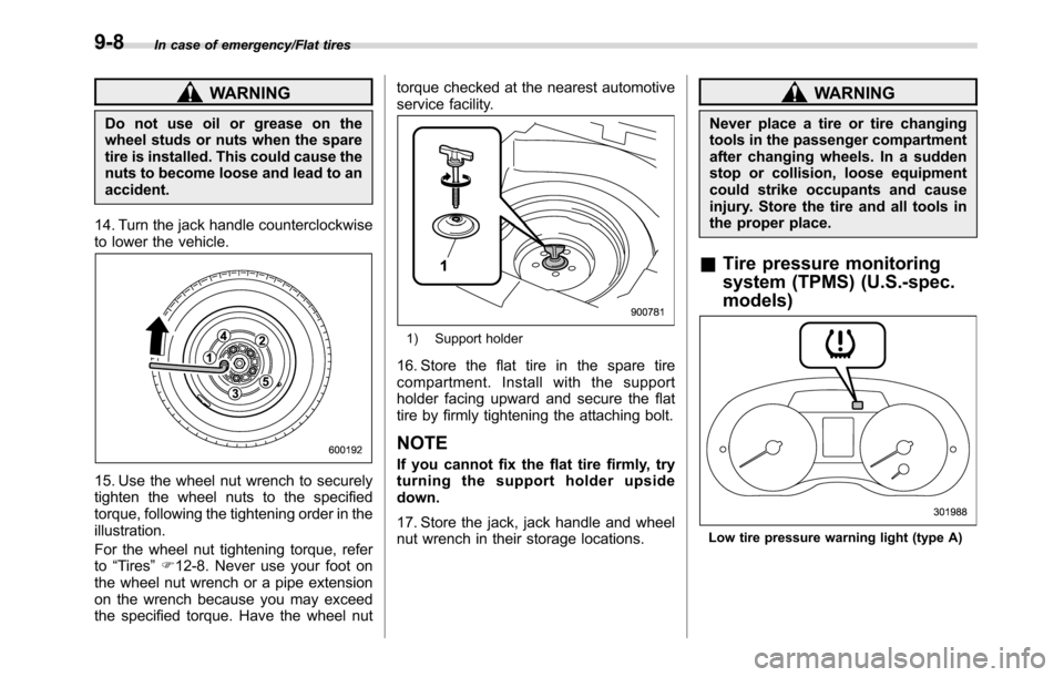
15. Use the wheel nut wrench to securely
tighten the wheel nuts to the specified
torque, following the tightening order in the
illustration.
For the wheel nut tightening torque, refer
to“Tires”F12-8. Never use your foot on
the wheel nut wrench or a pipe extension
on the wrench because you may exceed
the specified torque. Have the wheel nuttorque checked at the nearest automotive
service facility.
1) Support holder
16. Store the flat tire in the spare tire
compartment. Install with the support
holder facing upward and secure the flat
tire by firmly tightening the attaching bolt.
NOTE
If you cannot fix the flat tire firmly, try
turning the support holder upside
down.
17. Store the jack, jack handle and wheel
nut wrench in their storage locations.
WARNING
Never place a tire or tire changing
tools in the passenger compartment
after changing wheels. In a sudden
stop or collision, loose equipment
could strike occupants and cause
injury. Store the tire and all tools in
the proper place.
&Tire pressure monitoring
system (TPMS) (U.S.-spec.
models)
Low tire pressure warning light (type A)
9-8
Page 531 of 572
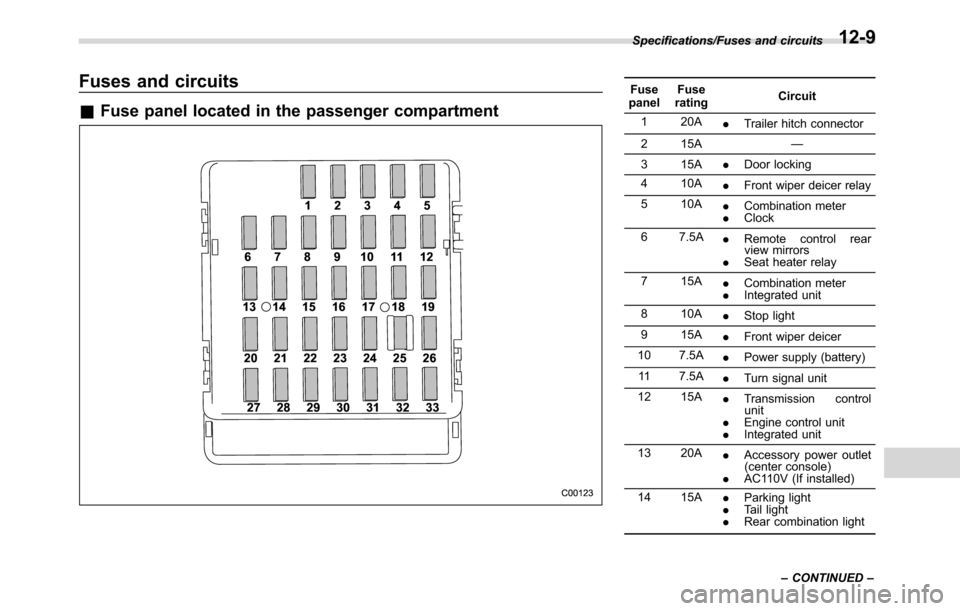
Fuses and circuits
&Fuse panel located in the passenger compartment
Fuse
panelFuse
ratingCircuit
1 20A
.Trailer hitch connector
2 15A—
3 15A
.Door locking
4 10A
.Front wiper deicer relay
5 10A
.Combination meter
.Clock
6 7.5A
.Remote control rear
view mirrors
.Seat heater relay
7 15A
.Combination meter
.Integrated unit
8 10A
.Stop light
9 15A
.Front wiper deicer
10 7.5A
.Power supply (battery)
11 7.5A
.Turn signal unit
12 15A
.Transmission control
unit
.Engine control unit
.Integrated unit
13 20A
.Accessory power outlet
(center console)
.AC110V (If installed)
14 15A
.Parking light
.Tail light
.Rear combination light Specifications/Fuses and circuits
–CONTINUED–
12-9
Page 544 of 572
Consumer information and Reporting safety defects/Tire information
.Extra load tire
A tire designed to operate at higher
loads and higher inflation pressure
than the corresponding standard
tire.
.Groove
The space between two adjacent
tread ribs.
.Innerliner
The layer(s) forming the inside sur-
face of a tubeless tire that contains
the inflating medium within the tire.
.Innerliner separation
The parting of the innerliner from
cord material in the carcass.
.Intended outboard sidewall
(1)The sidewall that contains a
whitewall, bears white lettering
or bears manufacturer, brand,
and/or model name molding that
is higher or deeper than the
same molding on the other side-
wall of the tire, or
(2)The outward facing sidewall
of an asymmetrical tire that has
a particular side that must al-
ways face outward when mount-ing on a vehicle.
.Light truck (LT) tire
A tire designated by its manufac-
turer as primarily intended for use
on lightweight trucks or multipur-
pose passenger vehicles.
.Load rating
The maximum load that a tire is
rated to carry for a given inflation
pressure.
.Maximum inflation pressure
The maximum cold inflation pres-
sure to which a tire may be inflated.
.Maximum load rating
The load rating for a tire at the
maximum permissible inflation
pressure for that tire.
.Maximum loaded vehicle weight
The sum of:
(a)Curb weight
(b)Accessory weight
(c)Vehicle capacity weight
(d)Production options weight.Maximum permissible inflation
pressure
The maximum cold inflation pres-
sure to which a tire may be inflated.
.Measuring rim
The rim on which a tire is fitted for
physical dimension requirements.
.Normal occupant weight
150 lbs (68 kg) times the number of
occupants specified in the second
column of Table 1 that is appended
to the end of this section.
.Occupant distribution
Distribution of occupants in a vehi-
cle as specified in the third column
of Table 1 that is appended to the
end of this section.
.Open splice
Any parting at any junction of tread,
sidewall, or innerliner that extends
to cord material.
.Outer diameter
The overall diameter of an inflated
new tire.
.Overall width
The linear distance between the
exteriors of the sidewalls of an
inflated tire, including elevations
due to labeling, decorations, or
protective bands or ribs.
13-6