glove box SUBARU CROSSTREK 2017 1.G Owners Manual
[x] Cancel search | Manufacturer: SUBARU, Model Year: 2017, Model line: CROSSTREK, Model: SUBARU CROSSTREK 2017 1.GPages: 572, PDF Size: 41.52 MB
Page 21 of 572
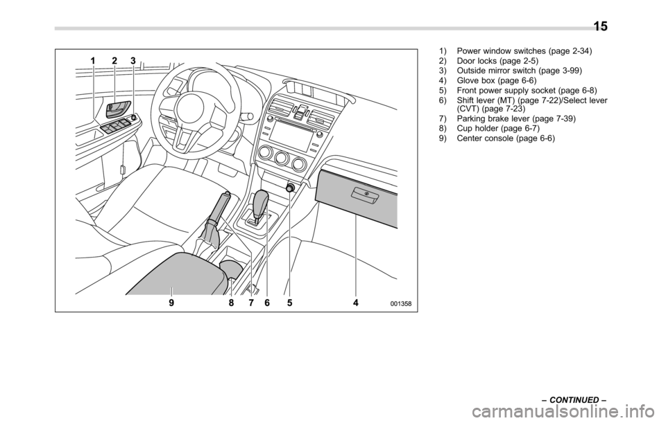
1) Power window switches (page 2-34)
2) Door locks (page 2-5)
3) Outside mirror switch (page 3-99)
4) Glove box (page 6-6)
5) Front power supply socket (page 6-8)
6) Shift lever (MT) (page 7-22)/Select lever
(CVT) (page 7-23)
7) Parking brake lever (page 7-39)
8) Cup holder (page 6-7)
9) Center console (page 6-6)
–CONTINUED–
15
Page 78 of 572
Seat, seatbelt and SRS airbags/*SRS airbag (Supplemental Restraint System airbag)
&SUBARU advanced frontal
airbag system
Your vehicle is equipped with a SUBARU
advanced frontal airbag system that com-
plies with the new advanced frontal airbag
requirements in the amended Federal
Motor Vehicle Safety Standard (FMVSS)
No. 208.
The SUBARU advanced frontal airbag
system automatically determines the de-
ployment force of the driver’s SRS frontal
airbag at the time of deployment as well as
whether or not to activate the front
passenger’s SRS frontal airbag and, if
activated, the deployment force of the
SRS frontal airbag at the time of deploy-
ment.
Your vehicle has warning labels on the
driver’s and front passenger’s sun visors
beginning with the phrase“EVEN WITH
ADVANCED AIR BAGS”and a tag
attached to the glove box lid beginning
with the phrase“Even with Advanced Air
Bags”. Make sure that you carefully read
the instructions on the warning labels and
tag.
Always wear your seatbelt. The SUBARU
advanced frontal airbag system is a
supplemental restraint system and must
be used in combination with a seatbelt. All
occupants should wear a seatbelt or be
seated in an appropriate child restraintsystem.
For the locations of the SRS airbags, refer
to“Components”F1-44.
In a moderate to severe frontal collision,
the following components deploy.
.SRS frontal airbag for driver
.SRS frontal airbag for front passenger
.SRS knee airbag for driver
.SRS curtain airbag*
1
*1: When an offset frontal collision that is severe
enough to deploy the front airbag occurs.
These components supplement the seat-
belts by reducing the impact to the
occupant’s head, chest and knees.
!Driver’s SRS frontal airbag
The driver’s SRS frontal airbag uses a
dual stage inflator. The inflator operates in
different ways depending on the severity
of impact.
Have the system inspected by your
SUBARU dealer immediately if the SRS
airbag system warning light illuminates.
NOTE
The driver’s SRS side airbag and SRS
curtain airbag are not controlled by the
SUBARU advanced frontal airbag sys-
tem.!Front passenger’s SRS frontal air-
bag
The front passenger’s SRS frontal airbag
uses a dual stage inflator. The inflator
operates in different ways depending on
the severity of impact.
The occupant detection system sensor is
installed under the seat upholstery and
monitors the physique and posture of the
front passenger. Using this information,
the occupant detection system determines
whether the front passenger’s SRS frontal
airbag should be deployed or not.
The occupant detection system may not
inflate the front passenger’s SRS frontal
airbag even when the driver’s SRS frontal
airbag deploys. This is normal. In this
case, although the front passenger’s SRS
frontal airbag does not operate, the front
passenger’s seatbelt pretensioner oper-
ates with the driver’s seatbelt preten-
sioner. For details about the seatbelt
pretensioner, refer to“Front seatbelt pre-
tensioners”F1-20.
CAUTION
Observe the following precautions.
Failure to do so may prevent the
SUBARU advanced frontal airbag
system from functioning correctly
or cause the system to fail.
1-46
Page 108 of 572
Keys and doors/Keyless access with push–button start system
&Access key
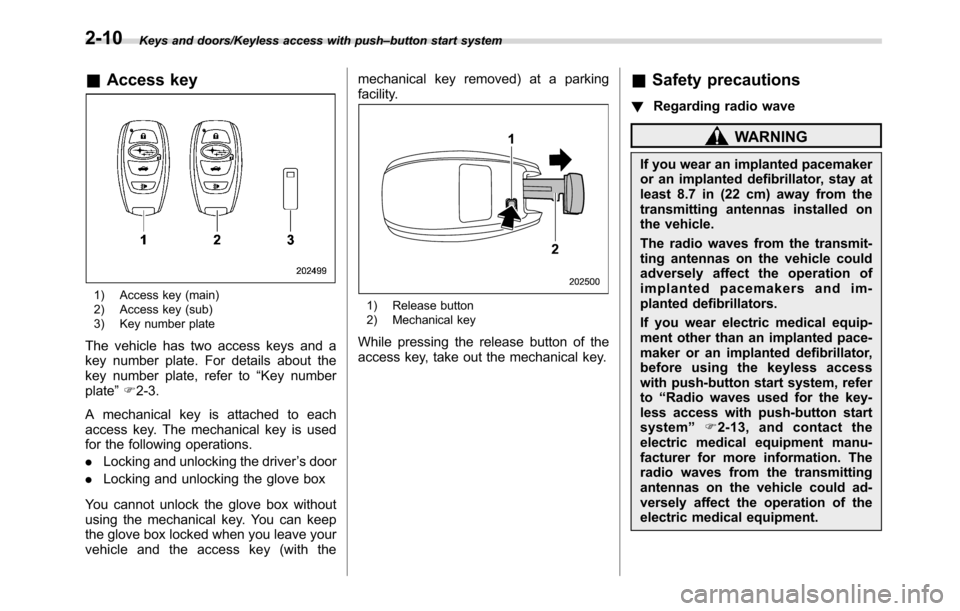
1) Access key (main)
2) Access key (sub)
3) Key number plate
The vehicle has two access keys and a
key number plate. For details about the
key number plate, refer to“Key number
plate”F2-3.
A mechanical key is attached to each
access key. The mechanical key is used
for the following operations.
.Locking and unlocking the driver’s door
.Locking and unlocking the glove box
You cannot unlock the glove box without
using the mechanical key. You can keep
the glove box locked when you leave your
vehicle and the access key (with themechanical key removed) at a parking
facility.
1) Release button
2) Mechanical key
While pressing the release button of the
access key, take out the mechanical key.
&Safety precautions
!Regarding radio wave
WARNING
If you wear an implanted pacemaker
or an implanted defibrillator, stay at
least 8.7 in (22 cm) away from the
transmitting antennas installed on
the vehicle.
The radio waves from the transmit-
ting antennas on the vehicle could
adversely affect the operation of
implanted pacemakers and im-
planted defibrillators.
If you wear electric medical equip-
ment other than an implanted pace-
maker or an implanted defibrillator,
before using the keyless access
with push-button start system, refer
to“Radio waves used for the key-
less access with push-button start
system”F2-13, and contact the
electric medical equipment manu-
facturer for more information. The
radio waves from the transmitting
antennas on the vehicle could ad-
versely affect the operation of the
electric medical equipment.
2-10
Page 110 of 572
Keys and doors/Keyless access with push–button start system
near personal computers or
home electric appliances.
NOTE
After the vehicle battery is discharged
or replaced, initialization of the steering
lock system may be required to start
the engine. In this case, perform the
following procedure to initialize the
steering lock.
1) Turn the push-button ignition
switch to the“OFF”position. For de-
tails, refer to“Switching power status”
F3-7.
2) Open and close the driver’s door.
3) Wait for approximately 10 seconds.
When the steering is locked, the initi-
alization is completed.
!Regarding access key
CAUTION
If the access key is dropped, the
integrated mechanical key inside
may become loose. Be careful not
to lose the mechanical key.
NOTE
.The access key is always commu-
nicating with the vehicle and is con-
tinuously using the battery. Although
the life of the battery varies depending
on the operating conditions, it is ap-
proximately 1 to 2 years. If the battery
becomes fully discharged, replace it
with a new one.
.If an access key is lost, it is
recommended that all of the remaining
access keys be reregistered. For rere-
gistration of an access key, contact a
SUBARU dealer.
.Up to 7 access keys can be regis-
tered for one vehicle. For a spare
access key, contact a SUBARU dealer.
.Carefully store the key number plate
supplied with the access key. It is
necessary for vehicle repair and addi-
tional registration of access keys.
.Do not leave the access key in the
storage spaces inside the vehicle.
Vibrations may damage the key or turn
on the switch, possibly resulting in a
lockout.
.Do not leave the access key in the
following places.
–On the instrument panel
–On the floor
–Inside the glove box
–Inside the door trim pocket–On the rear seat
–In the cargo area
If you do, the following situations
may occur.
–The access key is mistakenly
locked inside the vehicle.
–A false warning is issued
although no malfunction actually
occurs.
–No warning is issued even when
any malfunction occurs.
!Regarding setting
NOTE
.The operational/non-operational
setting for the keyless access function
can be changed. For the setting proce-
dure, refer to“Disabling keyless ac-
cess function”F2-17. The setting can
also be changed by a SUBARU dealer.
For more details, contact a SUBARU
dealer.
.For detailed information about the
operation method for the push-button
ignition switch while the keyless ac-
cess function is switched to the non-
operational mode, refer to“Access key
–if access key does not operate
properly”F9-17.
2-12
Page 144 of 572
Instruments and controls/Push–button ignition switch (models with push–button start system)
&Ignition switch light (if
equipped)
For easy access to the ignition switch in
the dark, the ignition switch light illumi-
nates when the driver’s door is opened or
when the driver’s door is unlocked using
the remote keyless entry transmitter.
The light remains illuminated for several
tens of seconds and then gradually turns
off under the following conditions.
.when the driver’s door is closed
.when the doors are unlocked using the
remote keyless entry transmitter
The light turns off immediately under the
following conditions.
.when the ignition switch is turned to the
“ON”position
.when all doors and the rear gate are
locked using the remote keyless entry
transmitter
Push-button ignition switch
(models with push-button
start system)
&Safety precautions
Refer to“Safety precautions”F2-10.
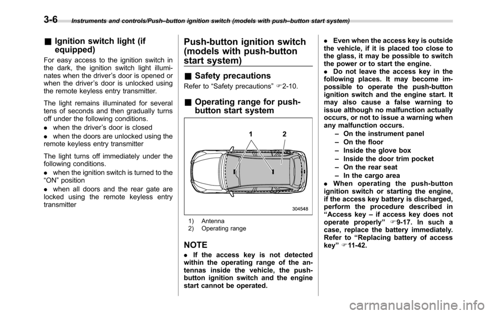
&Operating range for push-
button start system
1) Antenna
2) Operating range
NOTE
.If the access key is not detected
within the operating range of the an-
tennas inside the vehicle, the push-
button ignition switch and the engine
start cannot be operated..Even when the access key is outside
the vehicle, if it is placed too close to
the glass, it may be possible to switch
the power or to start the engine.
.Do not leave the access key in the
following places. It may become im-
possible to operate the push-button
ignition switch and the engine start. It
may also cause a false warning to
issue although no malfunction actually
occurs, or not to issue a warning when
any malfunction occurs.
–On the instrument panel
–On the floor
–Inside the glove box
–Inside the door trim pocket
–On the rear seat
–In the cargo area
.When operating the push-button
ignition switch or starting the engine,
if the access key battery is discharged,
perform the procedure described in
“Access key–if access key does not
operate properly”F9-17. In such a
case, replace the battery immediately.
Refer to“Replacing battery of access
key”F11-42.
3-6
Page 253 of 572
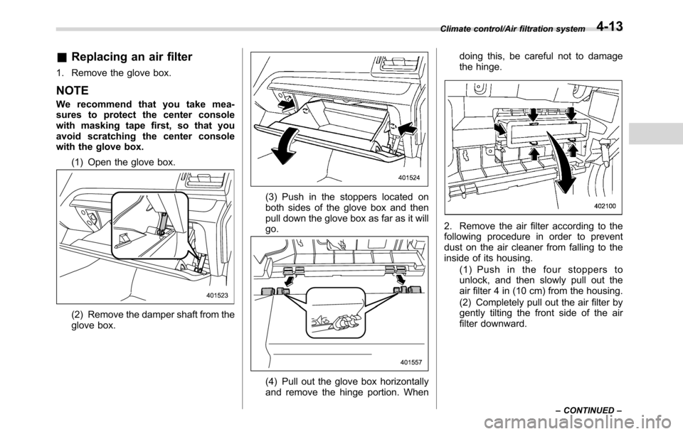
&Replacing an air filter
1. Remove the glove box.
NOTE
We recommend that you take mea-
sures to protect the center console
with masking tape first, so that you
avoid scratching the center console
with the glove box.
(1) Open the glove box.
(2) Remove the damper shaft from the
glove box.
(3) Push in the stoppers located on
both sides of the glove box and then
pull down the glove box as far as it will
go.
(4) Pull out the glove box horizontally
and remove the hinge portion. Whendoing this, be careful not to damage
the hinge.
2. Remove the air filter according to the
following procedure in order to prevent
dust on the air cleaner from falling to the
inside of its housing.
(1) Push in the four stoppers to
unlock, and then slowly pull out the
air filter 4 in (10 cm) from the housing.
(2) Completely pull out the air filter by
gently tilting the front side of the air
filter downward.
Climate control/Air filtration system
–CONTINUED–4-13
Page 254 of 572
Climate control/Air filtration system
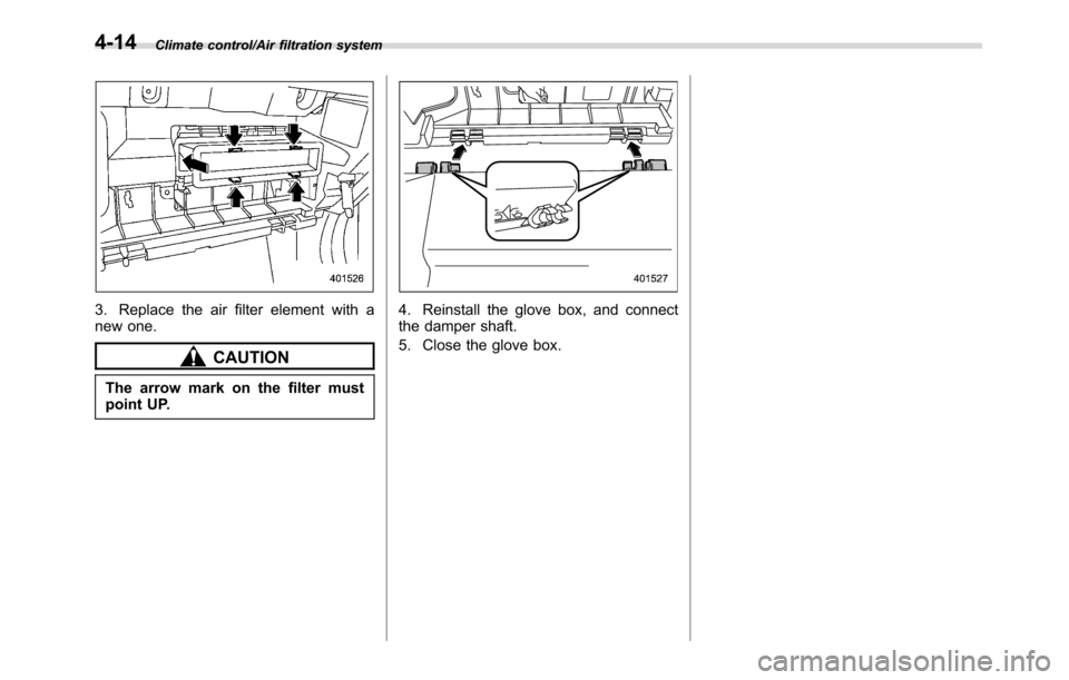
3. Replace the air filter element with a
new one.
CAUTION
The arrow mark on the filter must
point UP.
4. Reinstall the glove box, and connect
the damper shaft.
5. Close the glove box.
4-14
Page 349 of 572
Interior lights....................................................... 6-2
Dome light.......................................................... 6-2
Cargo area light.................................................. 6-2
Map lights........................................................... 6-3
OFF delay timer.................................................. 6-3
Sun visors........................................................... 6-4Sun visor extension plate (models with the
EyeSight system).............................................. 6-4
Vanity mirror....................................................... 6-5
Storage compartment......................................... 6-5Glove box........................................................... 6-6
Center console.................................................... 6-6
Cup holders......................................................... 6-7
Bottle holders...................................................... 6-7
Accessory power outlets.................................... 6-8
Use with a cigarette lighter (dealer option)........... 6-9
Ashtray (dealer option)...................................... 6-10
Floor mat (if equipped)...................................... 6-11
Coat hook........................................................... 6-11
Shopping bag hook........................................... 6-12
Cargo area cover (if equipped)......................... 6-12
Using the cover................................................. 6-12
To remove the cover housing ............................. 6-13
Stowage of the cargo area cover........................ 6-13
To install the cover housing............................... 6-14
Cargo tie-down hooks (if equipped)................. 6-14
Rear view camera.............................................. 6-15
How to use the rear view camera....................... 6-16
Viewing range on the screen.............................. 6-17
Help line............................................................ 6-18
Interior equipment
6
Page 354 of 572
Interior equipment/Storage compartment
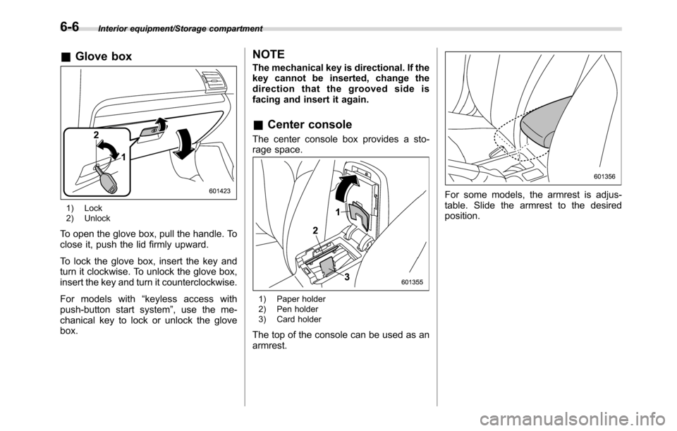
&Glove box
1) Lock
2) Unlock
To open the glove box, pull the handle. To
close it, push the lid firmly upward.
To lock the glove box, insert the key and
turn it clockwise. To unlock the glove box,
insert the key and turn it counterclockwise.
For models with“keyless access with
push-button start system”, use the me-
chanical key to lock or unlock the glove
box.
NOTE
The mechanical key is directional. If the
key cannot be inserted, change the
direction that the grooved side is
facing and insert it again.
&Center console
The center console box provides a sto-
rage space.
1) Paper holder
2) Pen holder
3) Card holder
The top of the console can be used as an
armrest.
For some models, the armrest is adjus-
table. Slide the armrest to the desired
position.
6-6
Page 561 of 572
Hood.................................................................... 11-5
Low oil level warning light....................................... 3-18
Oil................................................................ 11-8, 12-4
Overheating.......................................................... 9-12
Starting & stopping........................................... 7-9, 7-11
Event data recorder......................................................... 9
Exterior care.............................................................. 10-2
F
Flat tires..................................................................... 9-5
Floor mat.................................................................. 6-11
Fluid level
Brake.................................................................. 11-15
Clutch.................................................................. 11-16
Continuously variable transmission.......................... 11-15
Fog light
Bulb.......................................................... 11-38, 12-13
Indicator light......................................................... 3-31
Switch.................................................................. 3-93
Front
Differential gear oil........................................ 11-15, 12-6
Seatbelt pretensioners............................................ 1-20
Turn signal light.................................................... 11-38
Front seats.................................................................. 1-2
Forward and backward adjustment............................. 1-3
Head restraint adjustment......................................... 1-5
Reclining................................................................. 1-4
Seat height adjustment............................................. 1-4
Fuel........................................................................... 7-3
Consumption indicator............................................ 3-33
Consumption screen............................................... 3-48Economy hints........................................................ 8-2
Filler lid and cap...................................................... 7-4
Gauge................................................................... 3-12
Requirements................................................. 7-3, 12-3
Fuses..................................................................... 11-34
Fuses and circuits...................................................... 12-9
G
GAWR (Gross Axle Weight Rating) ............................... 8-13
Glove box................................................................... 6-6
GVWR (Gross Vehicle Weight Rating)........................... 8-13
H
Hands-free phone system............................................ 5-70
Hazard warning flasher.......................................... 3-8, 9-2
Head restraint adjustment
Front seat............................................................... 1-5
Rear seat............................................................... 1-8
Headlight
Beam leveler.......................................................... 3-93
Bulb replacing...................................................... 11-36
Bulb wattage........................................................ 12-13
Control switch........................................................ 3-88
Flasher.................................................................. 3-91
Indicator light......................................................... 3-32
Welcome lighting function........................................ 3-89
HID headlights...................................................... 1, 11-36
High beam indicator light............................................. 3-31
High/low beam change (dimmer).................................. 3-90
Hill start assist................................................. 7-41, 11-19
OFF indicator light.................................................. 3-23
Index14-5