SUBARU FORESTER 1999 Service Owner's Manual
Manufacturer: SUBARU, Model Year: 1999, Model line: FORESTER, Model: SUBARU FORESTER 1999Pages: 345, PDF Size: 5.6 MB
Page 21 of 345
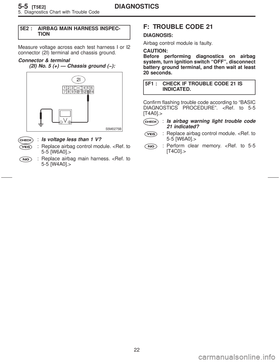
5E2 : AIRBAG MAIN HARNESS INSPEC-
TION
Measure voltage across each test harness I or I2
connector (2I) terminal and chassis ground.
Connector & terminal
(2I) No. 5 (+) Ð Chassis ground (þ):
S5M0275B
:Is voltage less than 1 V?
: Replace airbag control module.
: Replace airbag main harness.
F: TROUBLE CODE 21
DIAGNOSIS:
Airbag control module is faulty.
CAUTION:
Before performing diagnostics on airbag
system, turn ignition switch ªOFFº, disconnect
battery ground terminal, and then wait at least
20 seconds.
5F1 : CHECK IF TROUBLE CODE 21 IS
INDICATED.
Confirm flashing trouble code according to ªBASIC
DIAGNOSTICS PROCEDUREº.
:Is airbag warning light trouble code
21 indicated?
: Replace airbag control module.
: Perform clear memory.
22
5-5[T5E2]DIAGNOSTICS
5. Diagnostics Chart with Trouble Code
Page 22 of 345
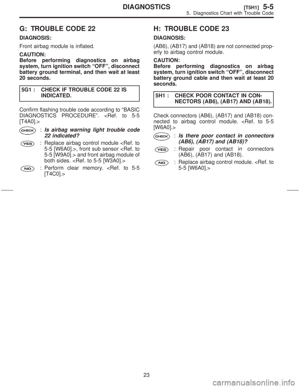
G: TROUBLE CODE 22
DIAGNOSIS:
Front airbag module is inflated.
CAUTION:
Before performing diagnostics on airbag
system, turn ignition switch ªOFFº, disconnect
battery ground terminal, and then wait at least
20 seconds.
5G1 : CHECK IF TROUBLE CODE 22 IS
INDICATED.
Confirm flashing trouble code according to ªBASIC
DIAGNOSTICS PROCEDUREº.
:Is airbag warning light trouble code
22 indicated?
: Replace airbag control module
both sides.
: Perform clear memory.
H: TROUBLE CODE 23
DIAGNOSIS:
(AB6), (AB17) and (AB18) are not connected prop-
erly to airbag control module.
CAUTION:
Before performing diagnostics on airbag
system, turn ignition switch ªOFFº, disconnect
battery ground cable and then wait at least 20
seconds.
5H1 : CHECK POOR CONTACT IN CON-
NECTORS (AB6), (AB17) AND (AB18).
Check connectors (AB6), (AB17) and (AB18) con-
nected to airbag control module.
:Is there poor contact in connectors
(AB6), (AB17) and (AB18)?
: Repair poor contact in connectors
(AB6), (AB17) and (AB18).
: Replace airbag control module.
23
[T5H1]5-5DIAGNOSTICS
5. Diagnostics Chart with Trouble Code
Page 23 of 345

I: TROUBLE CODE 24
DIAGNOSIS:
IAirbag control module is faulty.
IAirbag main harness circuit is open.
IFuse No. 11 (in joint box) is blown.
IBody harness circuit is open.
CAUTION:
Before performing diagnostics on airbag
system, turn ignition switch ªOFFº, disconnect
battery ground cable and then wait at least 20
seconds.
After 20 seconds elapse, remove instrument
panel lower cover, and disconnect (AB3) and
(AB8), (AB9) and (AB10).
5I1 : AIRBAG CONTROL MODULE INSPEC-
TION
1) Disconnect connector (AB6) from airbag control
module
test harness I or I2 connector (1I).
2) Connect battery ground cable and turn ignition
switch ªONº (engine off).
3) Measure voltage across connector (2I) terminal
and chassis ground.
Connector & terminal
(2I) No. 3 (+) Ð Chassis ground (þ):
S5M0264B
:Is voltage more than 10 V?
: Replace airbag control module.
: Go to step5I2.5I2 : AIRBAG MAIN HARNESS INSPEC-
TION
1) Go to following procedure after performing
diagnostics on airbag system as per diagnosis pro-
cedure under ª5I1 AIRBAG CONTROL MODULE
INSPECTIONº
lined.
2) Turn ignition switch ªOFFº, disconnect battery
ground cable and then wait at least 20 seconds.
3) Disconnect connector (AB1) from body harness
connector (B31) located in front pillar lower (driver
side), and connect connector (AB1) to test harness
A connector (2A).
B5M0122B
4) Measure resistance between test harness A
connector (5A) and test harness I or I2 connector
(2I) terminals.
Connector & terminal
(5A) No. 9 Ð (2I) No. 3:
S5M0265B
:Is resistance less than 10W?
: Go to step5I3.
: Replace airbag main harness.
24
5-5[T5I0]DIAGNOSTICS
5. Diagnostics Chart with Trouble Code
Page 24 of 345

5I3 : AIRBAG MAIN HARNESS INSPEC-
TION
Measure resistance between each terminal of con-
nectors (5A) and chassis ground.
Connector & terminal
(5A) No. 9 (+) Ð Chassis ground (þ):
S5M0266A
:Is resistance more than 10 kW?
: Go to step5I4.
: Replace airbag main harness.
5I4 : AIRBAG MAIN HARNESS INSPEC-
TION
Measure resistance between each terminal of con-
nectors (2I) and chassis ground.
Connector & terminal
(2I) No. 3 (+) Ð Chassis ground (þ):
S5M0267B
:Is resistance more than 10 kW?
: Go to step5I5.
: Replace airbag main harness.
TION
Make sure ignition switch is turned ªOFFº, then
remove and visually check fuse No. 11 (in joint
box).
S5M0257B
:Is fuse No. 11 blown?
: Replace fuse No. 11. If fuse No. 11
blows again, repair body harness.
: Repair body harness.
25
[T5I5]5-5DIAGNOSTICS
5. Diagnostics Chart with Trouble Code
Page 25 of 345
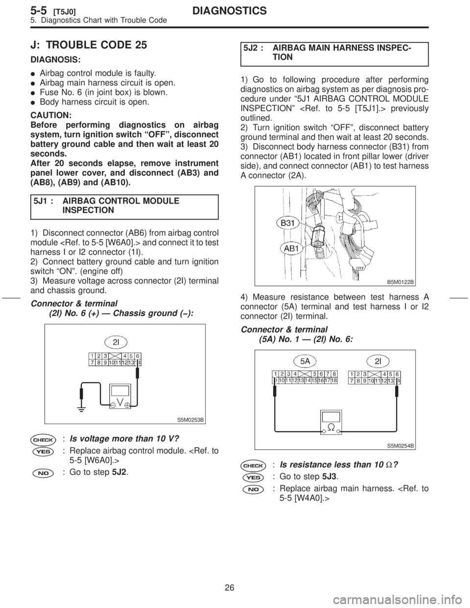
J: TROUBLE CODE 25
DIAGNOSIS:
IAirbag control module is faulty.
IAirbag main harness circuit is open.
IFuse No. 6 (in joint box) is blown.
IBody harness circuit is open.
CAUTION:
Before performing diagnostics on airbag
system, turn ignition switch ªOFFº, disconnect
battery ground cable and then wait at least 20
seconds.
After 20 seconds elapse, remove instrument
panel lower cover, and disconnect (AB3) and
(AB8), (AB9) and (AB10).
5J1 : AIRBAG CONTROL MODULE
INSPECTION
1) Disconnect connector (AB6) from airbag control
module
harness I or I2 connector (1I).
2) Connect battery ground cable and turn ignition
switch ªONº. (engine off)
3) Measure voltage across connector (2I) terminal
and chassis ground.
Connector & terminal
(2I) No. 6 (+) Ð Chassis ground (þ):
S5M0253B
:Is voltage more than 10 V?
: Replace airbag control module.
: Go to step5J2.5J2 : AIRBAG MAIN HARNESS INSPEC-
TION
1) Go to following procedure after performing
diagnostics on airbag system as per diagnosis pro-
cedure under ª5J1 AIRBAG CONTROL MODULE
INSPECTIONº
outlined.
2) Turn ignition switch ªOFFº, disconnect battery
ground terminal and then wait at least 20 seconds.
3) Disconnect body harness connector (B31) from
connector (AB1) located in front pillar lower (driver
side), and connect connector (AB1) to test harness
A connector (2A).
B5M0122B
4) Measure resistance between test harness A
connector (5A) terminal and test harness I or I2
connector (2I) terminal.
Connector & terminal
(5A) No. 1 Ð (2I) No. 6:
S5M0254B
:Is resistance less than 10W?
: Go to step5J3.
: Replace airbag main harness.
26
5-5[T5J0]DIAGNOSTICS
5. Diagnostics Chart with Trouble Code
Page 26 of 345
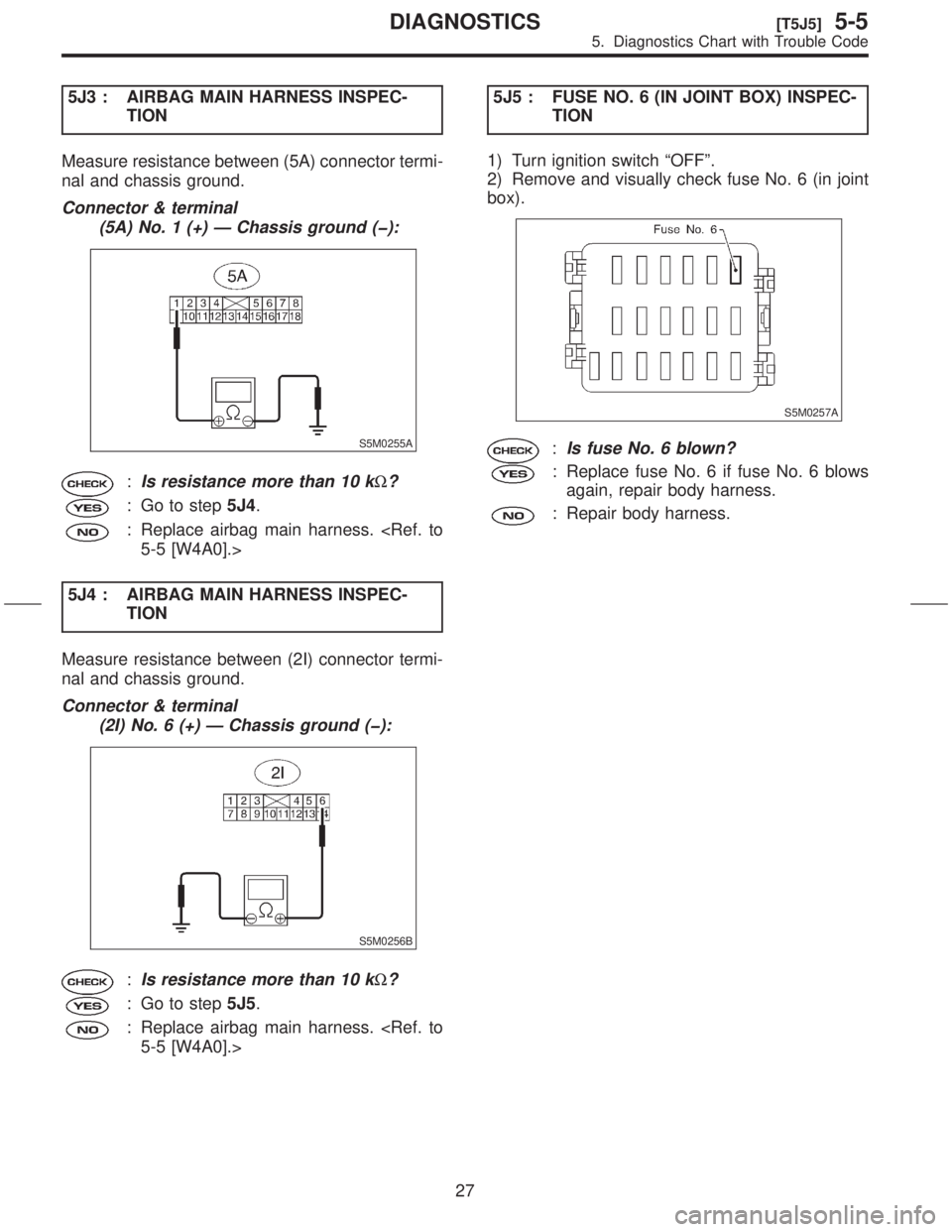
5J3 : AIRBAG MAIN HARNESS INSPEC-
TION
Measure resistance between (5A) connector termi-
nal and chassis ground.
Connector & terminal
(5A) No. 1 (+) Ð Chassis ground (þ):
S5M0255A
:Is resistance more than 10 kW?
: Go to step5J4.
: Replace airbag main harness.
5J4 : AIRBAG MAIN HARNESS INSPEC-
TION
Measure resistance between (2I) connector termi-
nal and chassis ground.
Connector & terminal
(2I) No. 6 (+) Ð Chassis ground (þ):
S5M0256B
:Is resistance more than 10 kW?
: Go to step5J5.
: Replace airbag main harness.
TION
1) Turn ignition switch ªOFFº.
2) Remove and visually check fuse No. 6 (in joint
box).
S5M0257A
:Is fuse No. 6 blown?
: Replace fuse No. 6 if fuse No. 6 blows
again, repair body harness.
: Repair body harness.
27
[T5J5]5-5DIAGNOSTICS
5. Diagnostics Chart with Trouble Code
Page 27 of 345
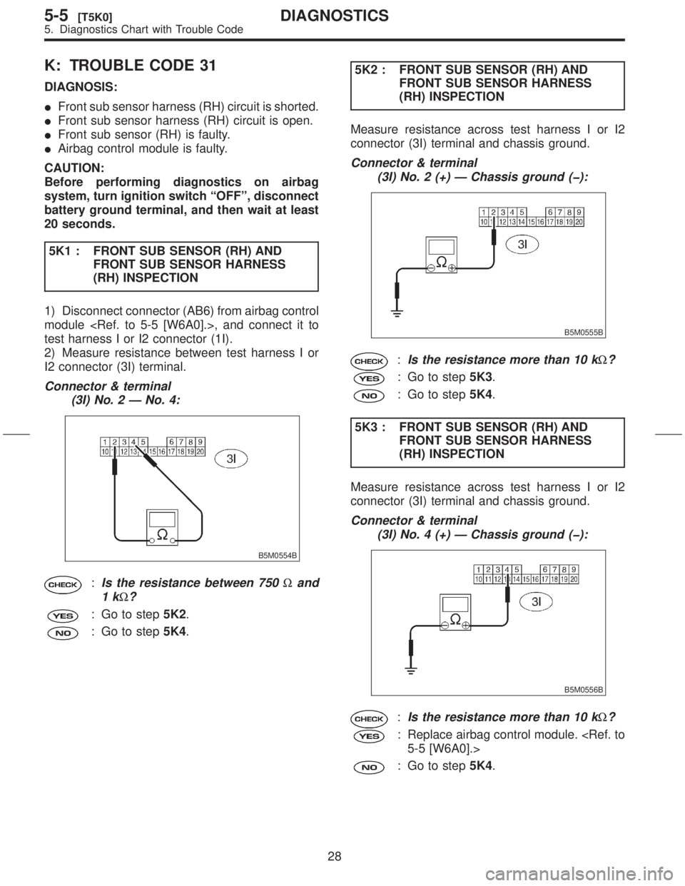
K: TROUBLE CODE 31
DIAGNOSIS:
IFront sub sensor harness (RH) circuit is shorted.
IFront sub sensor harness (RH) circuit is open.
IFront sub sensor (RH) is faulty.
IAirbag control module is faulty.
CAUTION:
Before performing diagnostics on airbag
system, turn ignition switch ªOFFº, disconnect
battery ground terminal, and then wait at least
20 seconds.
5K1 : FRONT SUB SENSOR (RH) AND
FRONT SUB SENSOR HARNESS
(RH) INSPECTION
1) Disconnect connector (AB6) from airbag control
module
test harness I or I2 connector (1I).
2) Measure resistance between test harness I or
I2 connector (3I) terminal.
Connector & terminal
(3I) No. 2 Ð No. 4:
B5M0554B
:Is the resistance between 750Wand
1k
W?
: Go to step5K2.
: Go to step5K4.5K2 : FRONT SUB SENSOR (RH) AND
FRONT SUB SENSOR HARNESS
(RH) INSPECTION
Measure resistance across test harness I or I2
connector (3I) terminal and chassis ground.
Connector & terminal
(3I) No. 2 (+) Ð Chassis ground (þ):
B5M0555B
:Is the resistance more than 10 kW?
: Go to step5K3.
: Go to step5K4.
5K3 : FRONT SUB SENSOR (RH) AND
FRONT SUB SENSOR HARNESS
(RH) INSPECTION
Measure resistance across test harness I or I2
connector (3I) terminal and chassis ground.
Connector & terminal
(3I) No. 4 (+) Ð Chassis ground (þ):
B5M0556B
:Is the resistance more than 10 kW?
: Replace airbag control module.
: Go to step5K4.
28
5-5[T5K0]DIAGNOSTICS
5. Diagnostics Chart with Trouble Code
Page 28 of 345

5K4 : FRONT SUB SENSOR (RH) INSPEC-
TION
1) Connect test harness H connector (2H) and
front sub sensor (RH).
2) Measure resistance between test harness H
connector (3H) terminal.
Connector & terminal
(3H) No. 3 Ð No. 4:
B5M0566A
:Is the resistance between 750Wand
1k
W?
: Go to step5K5.
: Replace front sub sensor (RH).
5K5 : FRONT SUB SENSOR (RH) INSPEC-
TION
Measure resistance across test harness H connec-
tor (3H) terminal and chassis ground.
Connector & terminal
(3H) No. 3 (+) Ð Chassis ground (þ):
B5M0567A
:Is the resistance less than 10 kW?
: Go to step5K6.
: Replace front sub sensor (RH).
TION
Measure resistance across test harness H connec-
tor (3H) terminal and chassis ground.
Connector & terminal
(3H) No. 4 (+) Ð Chassis ground (þ):
B5M0568A
:Is the resistance less than 10 kW?
: Go to step5K7.
: Replace front sub sensor (RH).
29
[T5K6]5-5DIAGNOSTICS
5. Diagnostics Chart with Trouble Code
Page 29 of 345
![SUBARU FORESTER 1999 Service Owners Manual 5K7 : FRONT SUB SENSOR HARNESS
(RH) INSPECTION
1) Connect test harness I or I2 connector (1I) and
connector (AB6).
2) Disconnect connector (AB16) from front sub
sensor (RH) <Ref. to 5-5 [W9A0].> and t SUBARU FORESTER 1999 Service Owners Manual 5K7 : FRONT SUB SENSOR HARNESS
(RH) INSPECTION
1) Connect test harness I or I2 connector (1I) and
connector (AB6).
2) Disconnect connector (AB16) from front sub
sensor (RH) <Ref. to 5-5 [W9A0].> and t](/img/17/57427/w960_57427-28.png)
5K7 : FRONT SUB SENSOR HARNESS
(RH) INSPECTION
1) Connect test harness I or I2 connector (1I) and
connector (AB6).
2) Disconnect connector (AB16) from front sub
sensor (RH)
harness H connector (1H) and connector (AB16).
3) Measure resistance between test harness I or
I2 connector (3I) terminal and test harness H con-
nector (3H) terminal.
Connector & terminal
(3I) No. 2 Ð (3H) No. 5:
S5M0352A
:Is the resistance less than 10W?
: Go to step5K8.
: Replace front sub sensor harness (RH)
harness.
(RH) INSPECTION
Measure resistance between test harness I or I2
connector (3I) terminal and test harness H connec-
tor (3H) terminal.
Connector & terminal
(3I) No. 4 Ð (3H) No. 6:
S5M0353A
:Is the resistance less than 10W?
: Go to step5K9.
: Replace front sub sensor harness (RH)
harness.
30
5-5[T5K7]DIAGNOSTICS
5. Diagnostics Chart with Trouble Code
Page 30 of 345
![SUBARU FORESTER 1999 Service Owners Manual 5K9 : FRONT SUB SENSOR HARNESS
(RH) INSPECTION
1) Connect test harness I or I2 connector (1I) and
connector (AB6).
2) Disconnect connector (AB16) from front sub
sensor (RH) <Ref. to 5-5 [W9A0].> and t SUBARU FORESTER 1999 Service Owners Manual 5K9 : FRONT SUB SENSOR HARNESS
(RH) INSPECTION
1) Connect test harness I or I2 connector (1I) and
connector (AB6).
2) Disconnect connector (AB16) from front sub
sensor (RH) <Ref. to 5-5 [W9A0].> and t](/img/17/57427/w960_57427-29.png)
5K9 : FRONT SUB SENSOR HARNESS
(RH) INSPECTION
1) Connect test harness I or I2 connector (1I) and
connector (AB6).
2) Disconnect connector (AB16) from front sub
sensor (RH)
harness H connector (1H) and connector (AB16).
3) Measure resistance between test harness I or
I2 connector (3I) terminal and test harness H con-
nector (3H) terminal.
Connector & terminal
(3I) No. 2 Ð (3H) No. 6:
S5M0419A
:Is the resistance more than 1 MW?
: Go to step5K10.
: Replace front sub sensor harness (RH)
harness.
(RH) INSPECTION
Measure resistance between test harness I or I2
connector (3I) terminal and test harness H connec-
tor (3H) terminal.
Connector & terminal
(3I) No. 4 Ð (3H) No. 5:
S5M0420A
:Is the resistance more than 1 MW?
: Go to step5K11.
: Replace front sub sensor harness (RH)
harness.
5K11 : FRONT SUB SENSOR HARNESS
(RH) INSPECTION
Measure resistance across test harness I or I2
connector (3I) terminal and chassis ground.
Connector & terminal
(3I) No. 2 (+) Ð Chassis ground (þ):
S5M0354A
:Is the resistance more than 10 kW?
: Go to step5K12.
: Replace front sub sensor harness (RH)
harness.
31
[T5K11]5-5DIAGNOSTICS
5. Diagnostics Chart with Trouble Code