engine oil SUBARU FORESTER 2004 Service Repair Manual
[x] Cancel search | Manufacturer: SUBARU, Model Year: 2004, Model line: FORESTER, Model: SUBARU FORESTER 2004Pages: 2870, PDF Size: 38.67 MB
Page 1697 of 2870

EN(H4DOTC)-67
ENGINE (DIAGNOSTIC)
Diagnostics for Engine Starting Failure
Step Check Yes No
1 CHECK SPARK PLUG CONDITION.
1) Remove the spark plug.
2) Check the spark plug condition.
plug.
2 CHECK IGNITION SYSTEM FOR SPARKS.
1) Connect the spark plug to ignition coil.
2) Release the fuel pressure.
PRESSURE, OPERATION, Fuel.>
3) Contact the spark plug’s thread portion on
engine.
4) While opening the throttle valve fully, crank
the engine to check that spark occurs at each
cylinder.Does spark occur at each cyl-
inder?Check fuel pump
system.
FUEL PUMP CIR-
CUIT, Diagnostics
for Engine Start-
ing Failure.>Go to step 3.
3 CHECK POWER SUPPLY CIRCUIT FOR IG-
NITION COIL & IGNITOR ASSY.
1) Turn the ignition switch to OFF.
2) Disconnect the connector from ignition coil
& ignitor ASSY.
3) Turn the ignition switch to ON.
4) Measure the power supply voltage between
ignition coil & ignitor ASSY connector and
engine ground.
Connector & terminal
(E31) No. 3 (+) — Engine ground (
−):
(E32) No. 3 (+) — Engine ground (
−):
(E33) No. 3 (+) — Engine ground (
−):
(E34) No. 3 (+) — Engine ground (
−):Is the voltage more than 10 V? Go to step 4.Repair the har-
ness and connec-
tor.
N
OTE:
In this case repair
the following:
Open circuit in
harness between
ignition coil & igni-
tor ASSY, and igni-
tion switch
connector
Poor contact in
coupling connector
4 CHECK HARNESS OF IGNITION COIL & IG-
NITOR ASSY GROUND CIRCUIT.
1) Turn the ignition switch to OFF.
2) Measure the resistance between ignition
coil & ignitor ASSY connector and engine
ground.
Connector & terminal
(E31) No. 2 — Engine ground:
(E32) No. 2 — Engine ground:
(E33) No. 2 — Engine ground:
(E34) No. 2 — Engine ground:Is the resistance less than 5
Ω?Go to step 5.Repair the har-
ness and connec-
tor.
NOTE:
In this case repair
the following:
Open circuit in
harness between
ignition coil & igni-
tor ASSY connec-
tor and engine
ground terminal
5 CHECK HARNESS BETWEEN ECM AND IG-
NITION COIL & IGNITOR ASSY CONNEC-
TOR.
1) Turn the ignition switch to OFF.
2) Disconnect the connector from ECM.
3) Disconnect the connector from ignition coil
& ignitor ASSY.
4) Measure the resistance of harness
between ECM and ignition coil & ignitor ASSY
connector.
Connector & terminal
(B135) No. 15 — (E34) No. 1:
(B135) No. 16 — (E33) No. 1:
(B135) No. 17 — (E32) No. 1:
(B135) No. 18 — (E31) No. 1:Is the resistance less than 1
Ω?Go to step 6.Repair the har-
ness and connec-
tor.
N
OTE:
In this case repair
the following:
OPEN CIR-
CUIT IN HAR-
NESS BETWEEN
ECM AND IGNI-
TION COIL &
IGNITOR ASSY
CONNECTOR.
Poor contact in
coupling connector
Page 1698 of 2870

EN(H4DOTC)-68
ENGINE (DIAGNOSTIC)
Diagnostics for Engine Starting Failure
6 CHECK HARNESS BETWEEN ECM AND IG-
NITION COIL & IGNITOR ASSY CONNEC-
TOR.
Measure the resistance of harness between
ECM and engine ground.
Connector & terminal:
(B135) No. 15 — Engine ground:
(B135) No. 16 — Engine ground:
(B135) No. 17 — Engine ground:
(B135) No. 18 — Engine ground:Is the resistance more than 1
MΩ?Go to step 7.Repair ground
short circuit in har-
ness between
ECM and ignition
coil & ignitor ASSY
connector.
7 CHECK POOR CONTACT.
Check poor contact in ECM connector.Is there poor contact in ECM
connector?Repair the poor
contact in ECM
connector.Replace the igni-
tion coil & ignitor
ASSY. Step Check Yes No
Page 1713 of 2870

EN(H4DOTC)-80
ENGINE (DIAGNOSTIC)
Diagnostic Procedure with Diagnostic Trouble Code (DTC)
19.Diagnostic Procedure with Diagnostic Trouble Code (DTC)
A: DTC P0011 “A” CAMSHAFT POSITION - TIMING OVER - ADVANCED OR
SYSTEM PERFORMANCE (BANK 1)
DTC DETECTING CONDITION:
Detect as soon as the malfunction occurs.
TROUBLE SYMPTOM:
Engine stalls.
Erroneous idling
CAUTION:
After repair or replacement of faulty parts, conduct Clear Memory Mode
Step Check Yes No
1 CHECK DTC ON DISPLAY.Is any other DTC displayed? Inspect the rele-
vant DTC using
“List of Diagnostic
Trouble Code
(DTC)”.
List of Diagnostic
Trouble Code
(DTC).>Go to step 2.
2 CHECK CURRENT DATA.
1) Start the engine and idle it.
2) Check the AVCS system operating angle
and oil flow control solenoid valve duty output
using Subaru Select Monitor or OBD-II general
scan tool.
N
OTE:
Subaru Select Monitor
For detailed operation procedure, refer to
“READ CURRENT DATA SHOWN ON DIS-
PLAY FOR ENGINE”.
OBD-II general scan tool
For detailed operation procedures, refer to the
OBD-II General Scan Tool Operation Manual.Is the AVCS system operating
angle approx. 0 degree and oil
flow control solenoid valve duty
output approx. 10%?A temporary poor
malfunction. Per-
for m the following
to clean oil routing.
Replace the
engine oil, and
then idle the
engine for 5 min-
utes and replace
the oil filter and
engine oil.Check the follow-
ing and repair or
replace it if neces-
sary.
Oil pipe (clog-
ging)
Oil flow con-
trol solenoid
valve (clogging
or dirt of oil
routing, spring
setting, clog-
ging of valve)
Intake cam-
shaft (dirt, dam-
age of
camshaft)
Timing belt
(alignment of
timing mark)
Page 1714 of 2870

EN(H4DOTC)-81
ENGINE (DIAGNOSTIC)
Diagnostic Procedure with Diagnostic Trouble Code (DTC)
B: DTC P0021 “A” CAMSHAFT POSITION - TIMING OVER - ADVANCED OR
SYSTEM PERFORMANCE (BANK 2)
DTC DETECTING CONDITION:
Detect as soon as the malfunction occurs.
TROUBLE SYMPTOM:
Engine stalls.
Erroneous idling
CAUTION:
After repair or replacement of faulty parts, conduct Clear Memory Mode
Step Check Yes No
1 CHECK DTC ON DISPLAY.Is any other DTC displayed? Inspect the rele-
vant DTC using
“List of Diagnostic
Trouble Code
(DTC)”.
List of Diagnostic
Trouble Code
(DTC).>Go to step 2.
2 CHECK CURRENT DATA.
1) Start the engine and idle it.
2) Check the AVCS system operating angle
and oil flow control solenoid valve duty output
using Subaru Select Monitor or OBD-II general
scan tool.
NOTE:
Subaru Select Monitor
For detailed operation procedure, refer to
“READ CURRENT DATA SHOWN ON DIS-
PLAY FOR ENGINE”.
OBD-II general scan tool
For detailed operation procedures, refer to the
OBD-II General Scan Tool Operation Manual.Is the AVCS system operating
angle approx. 0 degree and oil
flow control solenoid valve duty
output approx. 10%?A temporary poor
malfunction. Per-
for m the following
to clean oil routing.
Replace the
engine oil, and
then idle the
engine for 5 min-
utes and replace
the oil filter and
engine oil.Check the follow-
ing and repair or
replace it if neces-
sary.
Engine oil
(amount, dirt)
Oil pipe (clog-
ging)
Oil flow con-
trol solenoid
valve (clogging
or dirt of oil
routing, spring
setting, clog-
ging of valve)
Intake cam-
shaft (dirt, dam-
age of
camshaft)
Timing belt
(alignment of
timing mark)
Page 1801 of 2870

EN(H4DOTC)-168
ENGINE (DIAGNOSTIC)
Diagnostic Procedure with Diagnostic Trouble Code (DTC)
12 CHECK FUEL LEVEL.Is the fuel meter indication
higher than the “Lower” level?Go to step 13.Replenish fuel so
fuel meter indica-
tion is higher than
the “Lower”
level.After replen-
ishing fuel, Go to
step 13.
13 CHECK STATUS OF MALFUNCTION INDI-
CATOR LIGHT.
1) Clear the memory using Subaru Select
Monitor.
2) Start the engine, and drive the vehicle more
than 10 minutes.Does the malfunction indicator
light illuminate or blink?Go to step 15.Go to step 14.
14 CHECK CAUSE OF MISFIRE DIAGNOSED.Was the cause of misfire diag-
nosed when the engine is run-
ning?Finish diagnostics
operation, if the
engine has no
abnormality.Repair the poor
contact.
N
OTE:
In this case repair
the following:
Poor contact in
ignition coil con-
nector
Poor contact in
fuel injector con-
nector on faulty
cylinders
Poor contact in
ECM connector.
Poor contact in
coupling connector
15 CHECK AIR INTAKE SYSTEM.Is there any fault in air intake
system?Repair air intake
system.
N
OTE:
Check the follow-
ing items:
Are there air
leaks or air suction
caused by loose or
dislocated nuts
and bolts?
Are there cracks
or any disconnec-
tion of hoses?Go to step 16.
16 CHECK CYLINDER.Is there a fault in that cylinder? Repair or replace
the faulty par t.
N
OTE:
Check the follow-
ing items:
Spark plug
Fuel injector
CompressionGo to DTC P0171
and P0172.
148, DTC P0171
SYSTEM TOO
LEAN (BANK 1),
Diagnostic Proce-
dure with Diagnos-
tic Trouble Code
(DTC).> Step Check Yes No
Page 1816 of 2870

EN(H4DOTC)-183
ENGINE (DIAGNOSTIC)
Diagnostic Procedure with Diagnostic Trouble Code (DTC)
Step Check Yes No
1 CHECK CURRENT DATA.
1) Start the engine.
2) Drive the vehicle at the speed of approx. 30
km/h (19 MPH), and then measure the ignition
timing advance angle using Subaru Select
Monitor or OBD-II general scan tool.
N
OTE:
Subaru Select Monitor
For detailed operation procedure, refer to
“READ CURRENT DATA SHOWN ON DIS-
PLAY FOR ENGINE”.
OBD-II general scan tool
For detailed operation procedures, refer to the
OBD-II General Scan Tool Operation Manual.Does the ignition timing
advance angle changed
smoothly according to engine
output?
Idling: −2 — +2°
Driving: −2 — +50°Repair the poor
contact connector.
N
OTE:
In this case, repair
the following:
Poor contact of
AVCS camshaft
position sensor
connector.
Poor contact in
ECM connector.Go to step 2.
2 CHECK HARNESS BETWEEN AVCS CAM-
SHAFT POSITION SENSOR CONNECTOR
AND ECM CONNECTOR.
1) Turn the ignition switch to OFF.
2) Disconnect the connector from AVCS cam-
shaft position sensor connector and ECM.
3) Measure the resistance of harness
between AVCS camshaft position sensor con-
nector and engine ground.
Connector & terminal
(B36) No. 1 — (B135) No. 21:
(B36) No. 2 — (B135) No. 29:Is the resistance less than 1
Ω?Go to step 3.Repair the har-
ness and connec-
tor.
N
OTE:
In this case, repair
the following:
Open circuit in
harness between
AVCS camshaft
position sensor
connector and
ECM connector
Poor contact in
ECM connector
Poor contact in
coupling connector
3 CHECK HARNESS BETWEEN AVCS CAM-
SHAFT POSITION SENSOR CONNECTOR
AND ECM CONNECTOR.
Measure the resistance of harness between
AVCS camshaft position sensor connector and
engine ground.
Connector & terminal
(E36) No. 1 — Engine ground:
(E36) No. 2 — Engine ground:Is the resistance more than 1
MΩ?Go to step 4.Repair the ground
short circuit in har-
ness between
AVCS camshaft
position sensor
connector and
ECM connector.
NOTE:
The harness be-
tween both con-
nectors are
shielded.Repair
ground short circuit
in harness togeth-
er with shield.
4 CHECK CONDITION OF AVCS CAMSHAFT
POSITION SENSOR CONNECTOR.Is the AVCS camshaft position
sensor connector installation
bolt tightened securely?Go to step 5.Tighten the AVCS
camshaft position
sensor connector
installation bolt
securely.
5 CHECK AVCS CAMSHAFT POSITION SEN-
SOR CONNECTOR.
1) Remove the AVCS camshaft position sen-
sor.
2) Measure the resistance between the AVCS
camshaft position sensor connector terminals.
Te r m i n a l s
No. 1 — No. 2:Is the resistance 1 — 4 kΩ? Check for the clog-
ging on oil pres-
sure routing of oil
flow control sole-
noid valve.Replace the AVCS
camshaft position
sensor connector.
AVCS Camshaft
Position Sensor.>
Page 1818 of 2870

EN(H4DOTC)-185
ENGINE (DIAGNOSTIC)
Diagnostic Procedure with Diagnostic Trouble Code (DTC)
Step Check Yes No
1 CHECK CURRENT DATA.
1) Start the engine.
2) Drive the vehicle at the speed of approx. 30
km/h (19 MPH), and then measure the ignition
timing advance angle using Subaru Select
Monitor or OBD-II general scan tool.
N
OTE:
Subaru Select Monitor
For detailed operation procedure, refer to
“READ CURRENT DATA SHOWN ON DIS-
PLAY FOR ENGINE”.
OBD-II general scan tool
For detailed operation procedures, refer to the
OBD-II General Scan Tool Operation Manual.Does the ignition timing
advance angle changed
smoothly according to engine
output?
Idling: −2 — +2°
Driving: −2 — +50°Repair the poor
contact connector.
N
OTE:
In this case, repair
the following:
Poor contact of
AVCS camshaft
position sensor
connector.
Poor contact in
ECM connector.Go to step 2.
2 CHECK HARNESS BETWEEN AVCS CAM-
SHAFT POSITION SENSOR CONNECTOR
AND ECM CONNECTOR.
1) Turn the ignition switch to OFF.
2) Disconnect the connector from AVCS cam-
shaft position sensor connector and ECM.
3) Measure the resistance of harness
between AVCS camshaft position sensor con-
nector and engine ground.
Connector & terminal
(B35) No. 1 — (B135) No. 20:
(B35) No. 2 — (B135) No. 28:Is the resistance less than 1
Ω?Go to step 3.Repair the har-
ness and connec-
tor.
N
OTE:
In this case, repair
the following:
Open circuit in
harness between
AVCS camshaft
position sensor
connector and
ECM connector
Poor contact in
ECM connector.
Poor contact in
coupling connector
3 CHECK HARNESS BETWEEN AVCS CAM-
SHAFT POSITION SENSOR CONNECTOR
AND ECM CONNECTOR.
Measure the resistance of harness between
AVCS camshaft position sensor connector and
engine ground.
Connector & terminal
(E35) No. 1 — Engine ground:
(E35) No. 2 — Engine ground:Is the resistance more than 1
MΩ?Go to step 4.Repair the ground
short circuit in har-
ness between
AVCS camshaft
position sensor
connector and
ECM connector.
NOTE:
The harness be-
tween both con-
nectors are
shielded.Repair
ground short circuit
in harness togeth-
er with shield.
4 CHECK CONDITION OF AVCS CAMSHAFT
POSITION SENSOR CONNECTOR.Is the AVCS camshaft position
sensor connector installation
bolt tightened securely?Go to step 5.Tighten the AVCS
camshaft position
sensor connector
installation bolt
securely.
5 CHECK AVCS CAMSHAFT POSITION SEN-
SOR CONNECTOR.
1) Remove the AVCS camshaft position sen-
sor connector.
2) Measure the resistance between the AVCS
camshaft position sensor connector terminals.
Te r m i n a l s
No. 1 — No. 2:Is the resistance 1 — 4 kΩ? Check for the oil
clogging on oil
pressure routing of
oil flow control
solenoid valve.Replace the AVCS
camshaft position
sensor connector.
AVCS Camshaft
Position Sensor.>
Page 1920 of 2870
EN(H4DOTC)-287
ENGINE (DIAGNOSTIC)
Diagnostic Procedure with Diagnostic Trouble Code (DTC)
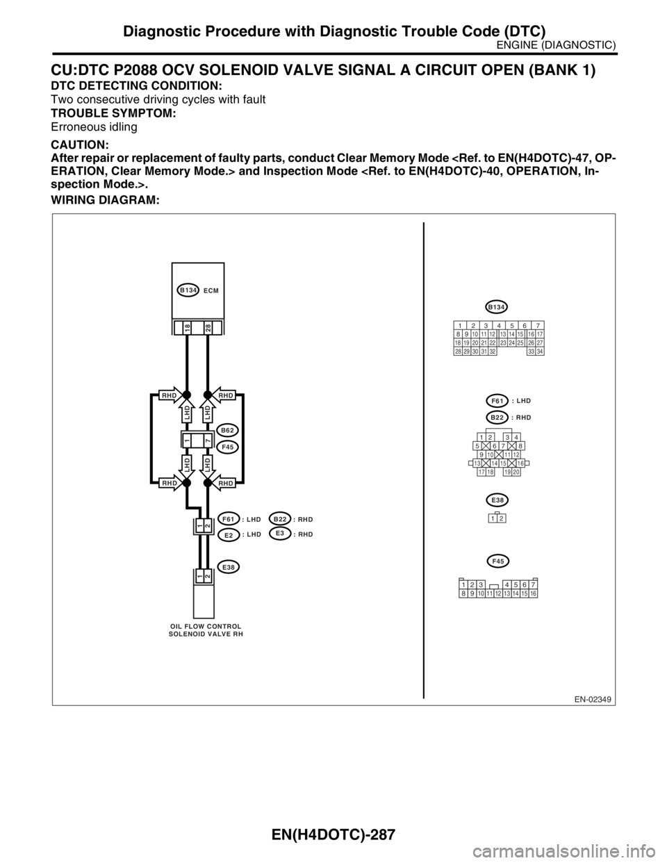
CU:DTC P2088 OCV SOLENOID VALVE SIGNAL A CIRCUIT OPEN (BANK 1)
DTC DETECTING CONDITION:
Two consecutive driving cycles with fault
TROUBLE SYMPTOM:
Erroneous idling
CAUTION:
After repair or replacement of faulty parts, conduct Clear Memory Mode
WIRING DIAGRAM:
EN-02349
F61
: LHD
E2
B134
B134
E38
OIL FLOW CONTROL
SOLENOID VALVE RHECM
28 2 1
2
1
B62
F45
RHD
RHD
LHD LHD
RHD
RHD
LHD LHD
: LHD
: RHD
B22
E38
F61
12
F45
B22
: RHD
18
125678
131415169101112
34
17181920
56 7
82 1
94 310
24 22 23 25 11 12 13 14 15
26 27
2816 17
18 19 20 21
33 34 29
32 30 31
12345678910111213141516
: LHDE3
: RHD
1
7
Page 1921 of 2870

EN(H4DOTC)-288
ENGINE (DIAGNOSTIC)
Diagnostic Procedure with Diagnostic Trouble Code (DTC)
Step Check Yes No
1 CHECK HARNESS BETWEEN ECM AND OIL
FLOW CONTROL SOLENOID VALVE.
1) Turn the ignition switch to OFF.
2) Disconnect the connector from ECM and oil
flow control solenoid valve.
3) Measure the resistance between ECM and
oil flow control solenoid valve.
Connector & terminal
(B134) No. 18 — (E38) No. 1:
(B134) No. 28 — (E38) No. 2:Is the resistance less than 1
Ω?Go to step 2.Repair open circuit
in harness
between ECM and
oil flow control
solenoid valve
connector.
N
OTE:
In this case, repair
the following:
Open circuit in
harness between
ECM and oil flow
control solenoid
valve connector
Poor contact in
coupling connector
2 CHECK HARNESS BETWEEN ECM AND OIL
FLOW CONTROL SOLENOID VALVE.
Measure the resistance between ECM and oil
flow control solenoid valve.
Connector & terminal
(E38) No. 1 — Engine ground:
(E38) No. 2 — Engine ground:Is the resistance more than 1
MΩ?Go to step 3.Repair short circuit
between ECM and
oil flow control
solenoid valve
connector.
3 CHECK OIL FLOW CONTROL SOLENOID
VALVE.
1) Remove the oil flow control solenoid valve
connector.
2) Measure the resistance between oil flow
control solenoid valve terminals.
Te r m i n a l s
No. 1 — No. 2:Is the resistance 6 — 12 Ω? Repair poor con-
tact in ECM and oil
flow control sole-
noid valve.Replace the oil
flow control sole-
noid valve.
68, Camshaft.>
Page 1922 of 2870
EN(H4DOTC)-289
ENGINE (DIAGNOSTIC)
Diagnostic Procedure with Diagnostic Trouble Code (DTC)
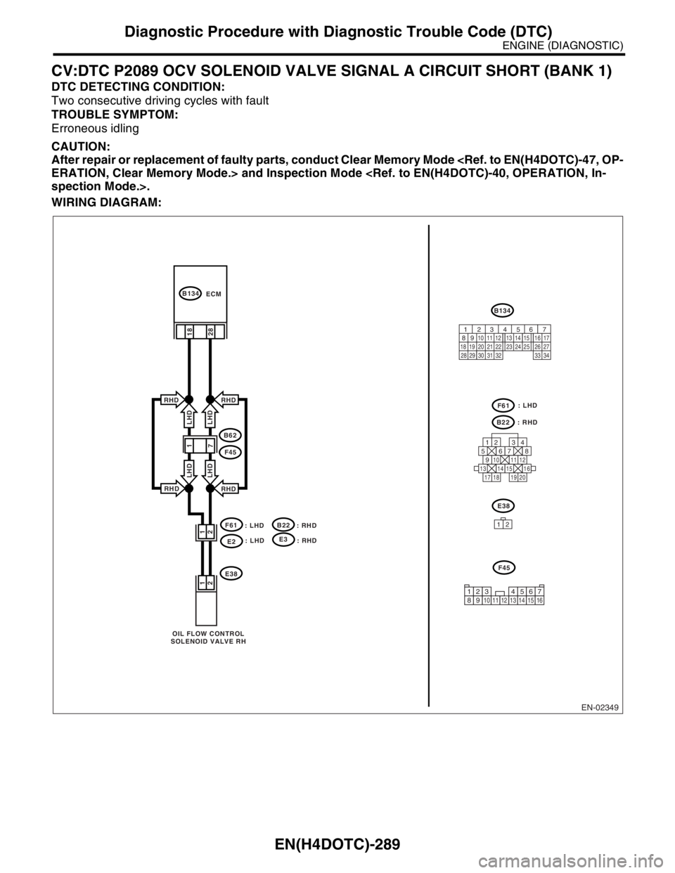
CV:DTC P2089 OCV SOLENOID VALVE SIGNAL A CIRCUIT SHORT (BANK 1)
DTC DETECTING CONDITION:
Two consecutive driving cycles with fault
TROUBLE SYMPTOM:
Erroneous idling
CAUTION:
After repair or replacement of faulty parts, conduct Clear Memory Mode
WIRING DIAGRAM:
EN-02349
F61
: LHD
E2
B134
B134
E38
OIL FLOW CONTROL
SOLENOID VALVE RHECM
28 2 1
2
1
B62
F45
RHD
RHD
LHD LHD
RHD
RHD
LHD LHD
: LHD
: RHD
B22
E38
F61
12
F45
B22
: RHD
18
125678
131415169101112
34
17181920
56 7
82 1
94 310
24 22 23 25 11 12 13 14 15
26 27
2816 17
18 19 20 21
33 34 29
32 30 31
12345678910111213141516
: LHDE3
: RHD
1
7