display SUBARU FORESTER 2004 Service Repair Manual
[x] Cancel search | Manufacturer: SUBARU, Model Year: 2004, Model line: FORESTER, Model: SUBARU FORESTER 2004Pages: 2870, PDF Size: 38.67 MB
Page 26 of 2870

AC-24
HVAC SYSTEM (HEATER, VENTILATOR AND A/C)
General Description
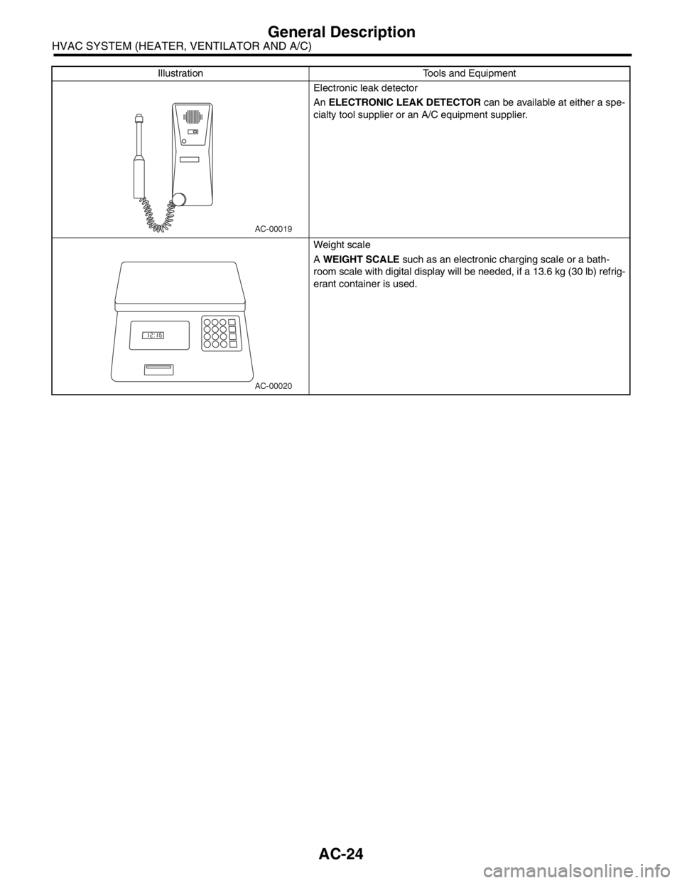
Electronic leak detector
An ELECTRONIC LEAK DETECTOR can be available at either a spe-
cialty tool supplier or an A/C equipment supplier.
Weight scale
A WEIGHT SCALE such as an electronic charging scale or a bath-
room scale with digital display will be needed, if a 13.6 kg (30 lb) refrig-
erant container is used. Illustration Tools and Equipment
AC-00019
AC-00020
Page 65 of 2870

AC-9
HVAC SYSTEM (AUTO A/C)(DIAGNOSTIC)
Diagnostic Chart for Self-Diagnosis
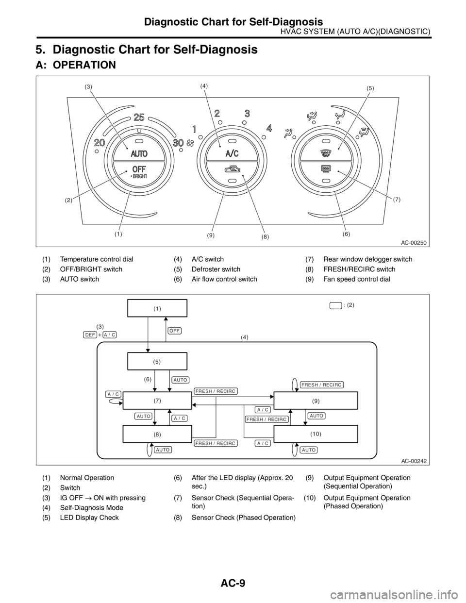
5. Diagnostic Chart for Self-Diagnosis
A: OPERATION
(1) Temperature control dial (4) A/C switch (7) Rear window defogger switch
(2) OFF/BRIGHT switch (5) Defroster switch (8) FRESH/RECIRC switch
(3) AUTO switch (6) Air flow control switch (9) Fan speed control dial
(1) Normal Operation (6) After the LED display (Approx. 20
sec.)(9) Output Equipment Operation
(Sequential Operation)
(2) Switch
(3) IG OFF → ON with pressing (7) Sensor Check (Sequential Opera-
tion)(10) Output Equipment Operation
(Phased Operation)
(4) Self-Diagnosis Mode
(5) LED Display Check (8) Sensor Check (Phased Operation)
AC-00250
(5)
(6)(7)
(8) (9) (4)
(3)
(2)
(1)
AC-00242
OFF
AUTO
AUTO
AUTO
AUTOAUTO
(5)(4) (3)
DEF A / C+
A / CA / C
A / C A / C
(6)
(7)
(8)(9)
(10)
FRESH / RECIRCFRESH / RECIRCFRESH / RECIRC
FRESH / RECIRC:
(2)
(1)
Page 134 of 2870

AB-2
AIRBAG SYSTEM (DIAGNOSTIC)
Basic Diagnostic Procedure
1. Basic Diagnostic Procedure
A: PROCEDURE
Step Check Yes No
1 READ DTC.
sis.Go to step 2.
2 READ DTC.
warning light.
Light Failure.>
3 PERFORM THE DIAGNOSIS.
1) Judge the possible cause from “List of
Diagnostic Trouble Code (DCT)”
2) Inspect using “Diagnostic Procedure with
Diagnostic Trouble Code (DTC)”.
3) Repair the cause of the trouble.
4) Perform the clear memory mode.
5) Perform the inspection mode.
6) Read any DTC again.Is DTC displayed? Perform the proce-
dure 1) to 5) in
step 3.Finish the diagno-
sis.
Page 216 of 2870

AB-84
AIRBAG SYSTEM (DIAGNOSTIC)
Diagnostic Procedure with Diagnostic Trouble Code (DTC)
R: DTC 53
DIAGNOSIS:
Side airbag sensor (RH) is faulty.
When Code 53 is displayed, the circuit within the side airbag sensor (RH) is faulty. Replace the side airbag
sensor (RH).
S: DTC 54
DIAGNOSIS:
Side airbag sensor (LH) is faulty.
When Code 53 is displayed, the circuit within the side airbag sensor (LH) is faulty. Replace the side airbag
sensor (LH).
T: DTC 55
This code is displayed when the side airbag is operate.
When this code is displayed, the memory cannot be erased. Replace the following parts.
Airbag control module.
Front seat with side airbag module. (Operating side)
Side airbag sensor. (Operating side)
Page 313 of 2870

ET-3
ENTERTAINMENT
Radio System
2. Radio System
A: WIRING DIAGRAM
1. RADIO
B: INSPECTION
Symptom Repair order
No power coming in. (No display and no sound from speakers.) (1) Check the fuse and power supply for radio.
(2) Check the radio ground.
(3) Remove the radio for repair.
A specific speaker does not operate. (1) Check the speaker.
(2) Check the output circuit between radio and speaker.
Radio generates noise with engine running. (1) Check the radio ground.
(2) Check the generator.
(3) Check the ignition coil.
(4) Remove the radio for repair.
AM and FM modes are weak or noisy. (1) Check the antenna.
(2) Check the antenna amplifier.
(3) Check the noise suppressor.
(4) Check the radio ground.
(5) Remove the radio for repair.
Page 387 of 2870

IDI-3
INSTRUMENTATION/DRIVER INFO
Combination Meter System
2. Combination Meter System
A: WIRING DIAGRAM
1. COMBINATION METER
2. OUTSIDE TEMPERATURE INDICATOR
Page 393 of 2870

IDI-9
INSTRUMENTATION/DRIVER INFO
Combination Meter System
2 CHECK HARNESS BETWEEN AMBIENT
SENSOR AND COMBINATION METER.
1) Turn the ignition switch to OFF.
2) Disconnect the connector from combination
meter.
3) Measure the resistance between ambient
sensor harness connector terminal and combi-
nation meter harness connector terminal.
Connector & terminal
(F78) No. 1 — (i10) No. 25:
(F78) No. 2 — (i10) No. 24:Is the resistance less than 10
Ω?Replace the com-
bination meter
printed circuit.Repair the wiring
harness.
3 CHECK AMBIENT SENSOR.
1) Remove the ambient sensor.
2) Check the ambient sensor.
ent sensor.
4 CHECK OUTSIDE TEMPERATURE INDICA-
TOR.
1) Connect the combination meter harness
connector.
2) Connect a resistor (3 kΩ) between termi-
nals of ambient sensor harness connector.
3) Turn the ignition switch to ON and check
the outside temperature indicator display.Does the outside temperature
indicator indicate 25°C (77°F)?Repair the poor
contact of ambient
sensor harness
connector.Replace the com-
bination meter
printed circuit. Step Check Yes No
Page 578 of 2870

CC(H4SO)-10
CRUISE CONTROL SYSTEM (DIAGNOSTIC)
Subaru Select Monitor
6) Turn the Subaru Select Monitor switch to ON.
7) On the Main Menu display screen, select the {All
System Diagnosis} and press [YES] key.
NOTE:
DTC is also shown in the {Each System Check} mode.
This mode is called up on the Cruise Control Diagnosis
screen by selecting the item {Cancel Code(s) Display}.
8) Drive the vehicle at least 30 km/h (19 MPH) with
cruise speed set.
9) If the cruise speed is canceled itself (without do-
ing any cancel operations), DTC will appear on se-
lect monitor display.
CAUTION:
DTC will also appear when cruise cancel is ef-
fected by driver. Do not confuse.
Have a co-worker ride in the vehicle to assist
in diagnosis during driving.
NOTE:
DTC will be cleared by turning the ignition switch or
cruise control main switch to OFF.3. REAL-TIME DIAGNOSIS
1) Connect the select monitor.
2) Turn the ignition switch and cruise control main
switch to ON.
3) Turn the Subaru Select Monitor switch to ON.
4) On the Main Menu display screen, select the
{Each System Check} and press [YES] key.
5) On the System Selection Menu display screen,
select the {Cruise Control} and press [YES] key.
6) Press the [YES] key after displayed the informa-
tion of engine type.
7) On the Cruise Control Diagnosis display screen,
select the {Current Data Display & Save} and press
[YES] key.
8) Make sure that normal indication is displayed
when controls are operated as indicated below:
Depress/release the brake pedal. (Stop light
switch and brake switch turn ON or OFF.)
Turn ON or OFF the “SET/COAST” switch.
Turn ON or OFF the “RESUME/ACCEL” switch.
Depress/release the clutch pedal. (MT model)
Set the selector lever to P or N. (AT model)
NOTE:
For detailed operation procedure, refer to the
SUBARU SELECT MONITOR OPERATION MAN-
UAL.
For detailed concerning DTC, refer to the List of
Diagnostic Trouble Code (DTC).
(1) Power switch
CC-00045
(1)
Page 620 of 2870

CC(H4DOTC 2.5)-8
CRUISE CONTROL SYSTEM (DIAGNOSTIC)
Subaru Select Monitor
5. Subaru Select Monitor
A: OPERATION
1. GENERAL
The on-board diagnosis function of the cruise con-
trol system uses the Subaru Select Monitor.
The on-board diagnosis function operates in two
categories, which are used depending on the type
of problems;
1) Cruise cancel conditions diagnosis:
(1) This category of diagnosis requires actual ve-
hicle driving in order to determine the cause, (as
when cruise speed is cancelled during driving al-
though cruise cancel condition is not entered).
(2) Cruise control memory of ECM stores the
cancel condition (Code No.) which occurred dur-
ing driving. When there are plural cancel condi-
tions (Code No.), they are shown on the Subaru
Select Monitor.
CAUTION:
The cruise control memory stores not only the
cruise “cancel” which occurred (although “can-
cel” operation is not entered by the driver), but
also the “cancel” condition input by the driver.
The content of memory is cleared when igni-
tion switch or cruise main switch is turned OFF.
2) Real-time diagnosis:
The real-time diagnosis function is used to deter-
mine whether or not the input signal system is in
good order, according to signal emitted from
switches, sensors, etc.
(1) Vehicle cannot be driven at cruise speed be-
cause problem occurs in the cruise control sys-
tem or its associated circuits.
(2) Monitor the signal conditions from switches
and sensors.
2. CRUISE CANCEL CONDITIONS DIAG-
NOSIS
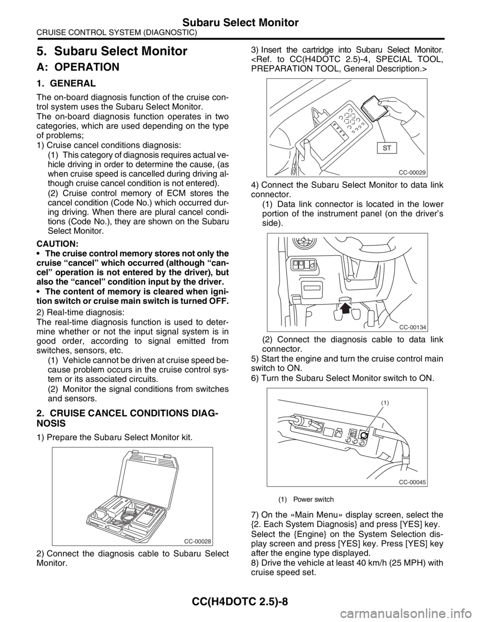
1) Prepare the Subaru Select Monitor kit.
2) Connect the diagnosis cable to Subaru Select
Monitor.3) Insert the cartridge into Subaru Select Monitor.
4) Connect the Subaru Select Monitor to data link
connector.
(1) Data link connector is located in the lower
portion of the instrument panel (on the driver’s
side).
(2) Connect the diagnosis cable to data link
connector.
5) Start the engine and turn the cruise control main
switch to ON.
6) Turn the Subaru Select Monitor switch to ON.
7) On the «Main Menu» display screen, select the
{2. Each System Diagnosis} and press [YES] key.
Select the {Engine} on the System Selection dis-
play screen and press [YES] key. Press [YES] key
after the engine type displayed.
8) Drive the vehicle at least 40 km/h (25 MPH) with
cruise speed set.
CC-00028
(1) Power switch
CC-00029
CC-00134
CC-00045
(1)
Page 621 of 2870

CC(H4DOTC 2.5)-9
CRUISE CONTROL SYSTEM (DIAGNOSTIC)
Subaru Select Monitor
9) If the cruise speed is canceled itself (without do-
ing any cancel operations), DTC will appear on se-
lect monitor display after {Cancel Code(s) Display}
is selected on the Engine Diagnosis display screen
and [YES] key is pressed.
CAUTION:
DTC will also appear when cruise cancel is ef-
fected by driver. Do not confuse.
Have a co-worker ride in the vehicle to assist
in diagnosis during driving.
NOTE:
DTC will be cleared by turning the ignition switch or
cruise control main switch to OFF.
3. REAL-TIME DIAGNOSIS
1) Connect the select monitor.
2) Turn the ignition switch and cruise control main
switch to ON.
3) Turn the Subaru Select Monitor switch to ON.
4) On the «Main Menu» display screen, select the
{2. Each System Check} and press [YES] key.
5) On the «System Selection» display screen, se-
lect the {Engine} and press [YES] key.
6) Press the [YES] key after the information of en-
gine type displayed.
7) On the «Engine Diagnosis» display screen, se-
lect the {Current Data Display & Save} and press
[YES] key.
8) Make sure that normal indication is displayed
when controls are operated as indicated below:
Depress/release the brake pedal. (Stop light
switch and brake switch turn ON.)
Turn ON the “SET/COAST” switch.
Turn ON the “RESUME/ACCEL” switch.
Turn ON the “CANCEL” switch. (The “SET/
COAST” and “RESUME/ACCEL” switch are turned
ON at same time.)
Depress/release the clutch pedal.
Set the shift lever to except for neutral position.
NOTE:
For detailed operation procedure, refer to the “SUB-
ARU SELECT MONITOR OPERATION MANUAL.”
For details concerning DTCs, refer to the “List of
Diagnostic Trouble Code (DTC).”
Code (DTC).>