CS-7
CONTROL SYSTEM
General Description
C: CAUTION
Wear working clothing, including a cap, protec-
tive goggles, and protective shoes during opera-
tion.
Remove contamination including dirt and corro-
sion before removal, installation or disassembly.
Keep the disassembled parts in order and pro-
tect them from dust or dirt.
Before removal, installation or disassembly, be
sure to clarify the failure. Avoid unnecessary re-
moval, installation, disassembly and replacement.
Use SUBARU genuine fluid, grease etc. or the
equivalent. Do not mix grease etc. with that of an-
other grade or from other manufacturers.
Be sure to tighten fasteners including bolts and
nuts to the specified torque.
Place shop jacks or rigid racks at the specified
points.
Apply grease onto sliding or revolution surfaces
before installation.
Before installing O-rings or snap rings, apply suf-
ficient amount of grease to avoid damage and de-
formation.
Before securing a part on a vise, place cushion-
ing material such as wood blocks, aluminum plate,
or cloth between the part and vise.
Before disconnecting electrical connectors, be
sure to disconnect the ground cable from battery.
5MT-32
MANUAL TRANSMISSION AND DIFFERENTIAL
Manual Transmission Assembly
3. Manual Transmission As-
sembly
A: REMOVAL
1) Set the vehicle on a lift.
2) Disconnect the ground cable from battery.
3) Drain the transmission gear oil completely.
to 5MT-31, REPLACEMENT, Transmission Gear
Oil.>
4) Open the front hood fully, and support with stay.
5) Remove the air intake duct and air cleaner case.
(Non-turbo model)
AL, Air Intake Duct.>
MOVAL, Air Cleaner Case.>
6) Remove the air cleaner case stay. (Non-turbo
model)
7) Remove the intercooler. (Turbo model)
IN(H4DOTC)-10, REMOVAL, Intercooler.>
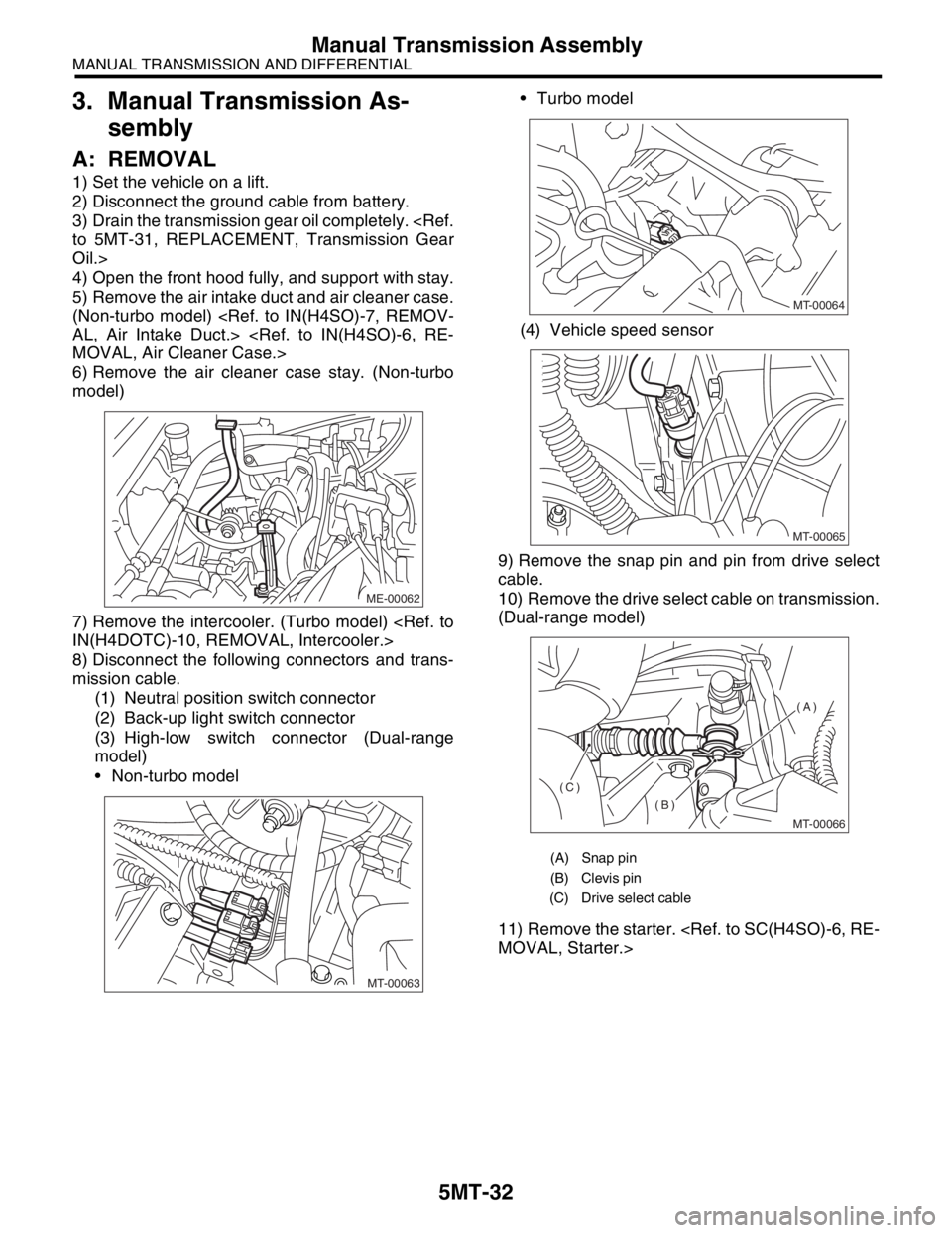
8) Disconnect the following connectors and trans-
mission cable.
(1) Neutral position switch connector
(2) Back-up light switch connector
(3) High-low switch connector (Dual-range
model)
Non-turbo model Turbo model
(4) Vehicle speed sensor
9) Remove the snap pin and pin from drive select
cable.
10) Remove the drive select cable on transmission.
(Dual-range model)
11) Remove the starter.
MOVAL, Starter.>
ME-00062
MT-00063
(A) Snap pin
(B) Clevis pin
(C) Drive select cable
MT-00064
MT-00065
MT-00066
(A)
(B)
(C)
5MT-38
MANUAL TRANSMISSION AND DIFFERENTIAL
Manual Transmission Assembly
24) Push clutch release lever to fit bearing into
clutch cover.
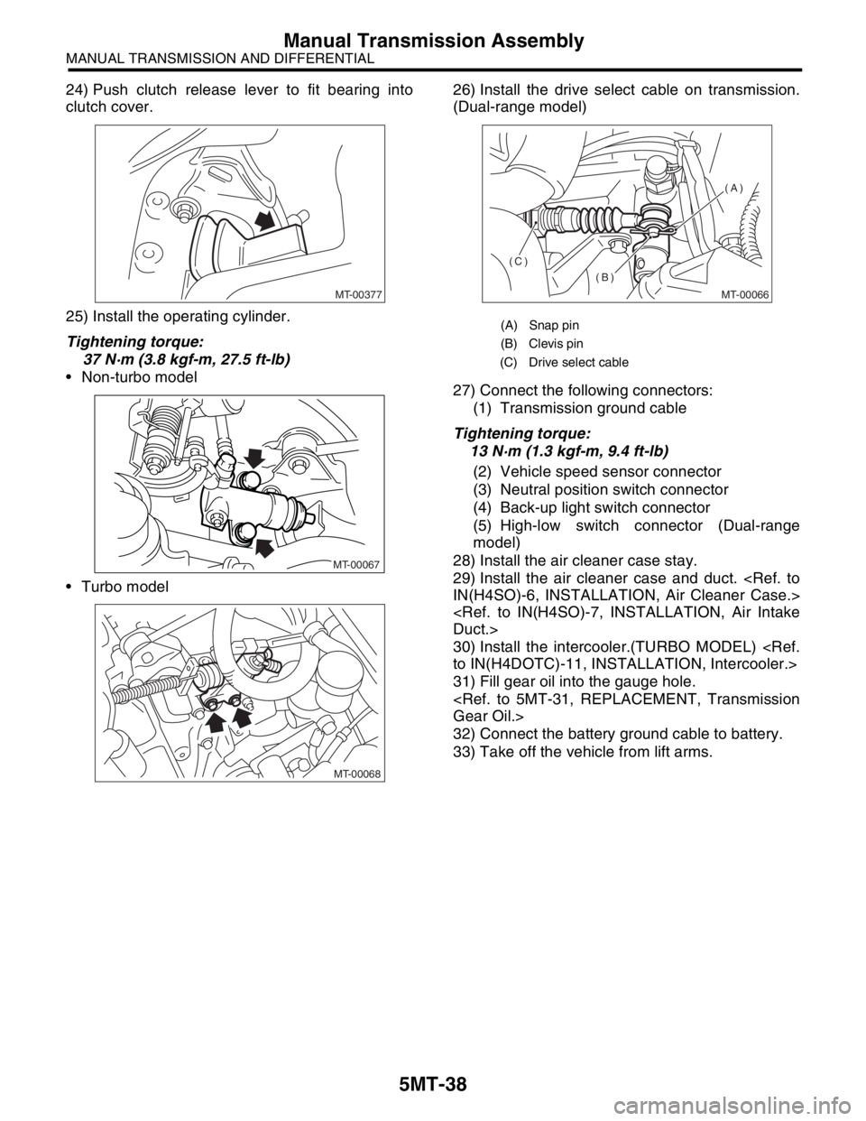
25) Install the operating cylinder.
Tightening torque:
37 N·m (3.8 kgf-m, 27.5 ft-lb)
Non-turbo model
Turbo model26) Install the drive select cable on transmission.
(Dual-range model)
27) Connect the following connectors:
(1) Transmission ground cable
Tightening torque:
13 N·m (1.3 kgf-m, 9.4 ft-lb)
(2) Vehicle speed sensor connector
(3) Neutral position switch connector
(4) Back-up light switch connector
(5) High-low switch connector (Dual-range
model)
28) Install the air cleaner case stay.
29) Install the air cleaner case and duct.
IN(H4SO)-6, INSTALLATION, Air Cleaner Case.>
Duct.>
30) Install the intercooler.(TURBO MODEL)
to IN(H4DOTC)-11, INSTALLATION, Intercooler.>
31) Fill gear oil into the gauge hole.
Gear Oil.>
32) Connect the battery ground cable to battery.
33) Take off the vehicle from lift arms.
MT-00377
MT-00067
MT-00068
(A) Snap pin
(B) Clevis pin
(C) Drive select cable
MT-00066
(A)
(B)
(C)