length SUBARU FORESTER 2004 Service Owner's Manual
[x] Cancel search | Manufacturer: SUBARU, Model Year: 2004, Model line: FORESTER, Model: SUBARU FORESTER 2004Pages: 2870, PDF Size: 38.67 MB
Page 1460 of 2870

ME(H4DOTC)-4
MECHANICAL
General Description
Piston Outer diameterSTDA 91.985 — 91.995 mm (3.6214 — 3.6218 in)
B 91.975 — 91.985 mm (3.6211 — 3.6214 in)
0.25 mm (0.0098 in)
OS92.225 — 92.235 mm (3.6309 — 3.6313 in)
0.50 mm (0.0197 in)
OS92.475 — 92.485 mm (3.6407 — 3.6411 in)
Piston pinStandard clearance between piston
pin and hole in pistonSTD 0.004 — 0.008 mm (0.0002 — 0.0003 in)
Limit 0.020 mm (0.0008 in)
Degree of fitPiston pin must be fitted into position with thumb at 20°C
(68°F).
Piston ringPiston ring gapTop ringSTD 0.20 — 0.25 mm (0.0079 — 0.0098 in)
Limit 1.0 mm (0.039 in)
Second
ringSTD 0.40 — 0.50 mm (0.016 — 0.020 in)
Limit 1.0 mm (0.039 in)
Oil ringSTD 0.20 — 0.50 mm (0.0079 — 0.020 in)
Limit 1.5 mm (0.059 in)
Clearance between piston
ring and piston ring
grooveTop ringSTD 0.040 — 0.080 mm (0.0016 — 0.0031 in)
Limit 0.15 mm (0.0059 in)
Second
ringSTD 0.030 — 0.070 mm (0.0012 — 0.0028 in)
Limit 0.15 mm (0.0059 in)
Connecting
rodBend twist per 100 mm (3.94 in) in
lengthLimit 0.10 mm (0.0039 in)
Side clearanceSTD 0.070 — 0.330 mm (0.0028 — 0.0130 in)
Limit 0.4 mm (0.016 in)
Connecting
rod bearingOil clearanceSTD 0.010 — 0.038 mm (0.0004 — 0.0015 in)
Limit 0.05 mm (0.0020 in)
Thickness at center portionSTD 1.486 — 1.498 mm (0.0585 — 0.0590 in)
0.03 mm
(0.0012
in) US1.504 — 1.512 mm (0.0592 — 0.0595 in)
0.05 mm
(0.0020
in) US1.514 — 1.522 mm (0.0596 — 0.0599 in)
0.25 mm
(0.0098
in) US1.614 — 1.622 mm (0.0635 — 0.0639 in)
Connecting
rod bushingClearance between piston pin and
bushingSTD 0 — 0.022 mm (0 — 0.0009 in)
Limit 0.030 mm (0.0012 in)
Page 1463 of 2870

ME(H4DOTC)-7
MECHANICAL
General Description
Belt ten-
sion
adjusterProtrusion of adjuster rod 5.7 — 6.7 mm (0.224 — 0.264 in)
Belt ten-
sionerSpacer O.D. 17.955 — 17.975 mm (0.7069 — 0.7077 in)
Tensioner bush I.D. 18.0 — 18.08 mm (0.7087 — 0.7118 in)
Clearance between spacer and bushSTD 0.025 — 0.125 mm (0.0010 — 0.0049 in)
Limit 0.175 mm (0.069 in)
Side clearance of spacerSTD 0.2 — 0.55 mm (0.0079 — 0.0217 in)
Limit 0.81 mm (0.0319 in)
CamshaftBend limit 0.020 mm (0.0079 in)
Thrust clearanceSTD 0.068 — 0.116 mm (0.0027 — 0.0046 in)
Limit 0.14 mm (0.0055 in)
Cam lobe heightIntakeSTD 46.55 — 46.65 mm (1.833 — 1.837 in)
Limit 46.45 mm (1.829 in)
ExhaustSTD 46.75 — 46.85 mm (1.841 — 1.844 in)
Limit 46.65 mm (1.837 in)
Journal O.D. STDFront 37.946 — 37.963 mm (1.4939 — 1.4946 in)
Center
rear29.946 — 29.963 mm (1.1790 — 1.1796 in)
Oil clearanceSTD 0.037 — 0.072 mm (0.0015 — 0.0028 in)
Limit 0.10 mm (0.0039 in)
Cylinder
headSurface warpage limit (mating with cylinder head) 0.05 mm (0.0020 in)
Surface grinding limit 0.3 mm (0.012 in)
Standard height 127.5 mm (5.02 in)
Va l ve s e a tRefacing angle 90°
Contacting widthIntakeSTD 1.0 mm (0.039 in)
Limit 1.7 mm (0.067 in)
ExhaustSTD 1.5 mm (0.059 in)
Limit 2.2 mm (0.087 in)
Valve guideInner diameter 6.000 — 6.012 mm (0.2362 — 0.2367 in)
Protrusion above head 15.8 — 16.2 mm (0.622 — 0.638 in)
Va l veHead edge thicknessIntakeSTD 1.2 mm (0.047 in)
Limit 0.8 mm (0.031 in)
ExhaustSTD 1.5 mm (0.059 in)
Limit 0.8 mm (0.031 in)
Stem diameterIntake 5.955 — 5.970 mm (0.2344 — 0.2350 in)
Exhaust 5.945 — 5.960 mm (0.2341 — 0.2346 in)
Stem oil clearanceSTDIntake 0.030 — 0.057 mm (0.0012 — 0.0022 in)
Exhaust 0.040 — 0.067 mm (0.0016 — 0.0026 in)
Limit — 0.15 mm (0.0059 in)
Overall lengthIntake 104.4 mm (4.110 in)
Exhaust 104.65 mm (4.120 in)
Va l ve
springFree length 47.32 mm (1.863 in)
Squareness 2.5°, 2.1 mm (0.083 in)
Tension/spring heightSet205 — 235 N (20.9 — 24.0 kgf, 46.1 — 52.8 lb)/
36.0 mm (1.417 in)
Lift426 — 490 N (43.4 — 50.0 kgf, 95.8 — 110 lb)/
26.50 mm (1.043 in)
Page 1464 of 2870

ME(H4DOTC)-8
MECHANICAL
General Description
Cylinder
blockSurface warpage limit (mating with cylinder head) 0.05 mm (0.0020 in)
Surface grinding limit 0.1 mm (0.004 in)
Standard height 201.0 mm (7.91 in)
Cylinder bore STDA 99.505 — 99.515 mm (3.9175 — 3.9179 in)
B 99.495 — 99.505 mm (3.9171 — 3.9175 in)
TaperSTD 0.015 mm (0.0006 in)
Limit 0.050 mm (0.0020 in)
Out-of-roundnessSTD 0.010 mm (0.0004 in)
Limit 0.050 mm (0.0020 in)
Piston clearanceSTD−0.010 — 0.010 mm (−0.0004 — 0.0004 in)
Limit 0.030 mm (0.0012 in)
Enlarging (boring) limit 0.5 mm (0.020 in)
Piston Outer diameterSTDA 99.505 — 99.515 mm (3.9175 — 3.9179 in)
B 99.495 — 99.505 mm (3.9171 — 3.9175 in)
0.25 mm (0.0098 in)
OS99.745 — 99.765 mm (3.9270 — 3.9278 in)
0.50 mm (0.0197 in)
OS99.995 — 100.015 mm (3.9368 — 3.9376 in)
Piston pinStandard clearance between piston
pin and hole in pistonSTD 0.004 — 0.008 mm (0.0002 — 0.0003 in)
Limit 0.020 mm (0.0008 in)
Degree of fitPiston pin must be fitted into position with thumb at 20°C
(68°F).
Piston ringPiston ring gapTop ringSTD 0.20 — 0.25 mm (0.0079 — 0.0098 in)
Limit 1.0 mm (0.039 in)
Second
ringSTD 0.37 — 0.52 mm (0.015 — 0.020 in)
Limit 1.0 mm (0.039 in)
Oil ringSTD 0.20 — 0.50 mm (0.0079 — 0.020 in)
Limit 1.5 mm (0.059 in)
Clearance between piston
ring and piston ring
grooveTop ringSTD 0.040 — 0.080 mm (0.0016 — 0.0031 in)
Limit 0.15 mm (0.0059 in)
Second
ringSTD 0.030 — 0.070 mm (0.0012 — 0.0028 in)
Limit 0.15 mm (0.0059 in)
Connecting
rodBend twist per 100 mm (3.94 in) in
lengthLimit 0.10 mm (0.0039 in)
Side clearanceSTD 0.070 — 0.330 mm (0.0028 — 0.0130 in)
Limit 0.4 mm (0.016 in)
Connecting
rod bearingOil clearanceSTD 0.017 — 0.045 mm (0.0007 — 0.0018 in)
Limit 0.05 mm (0.0020 in)
Thickness at center portionSTD 1.490 — 1.502 mm (0.0587 — 0.0591 in)
0.03 mm
(0.0012
in) US1.504 — 1.512 mm (0.0592 — 0.0595 in)
0.05 mm
(0.0020
in) US1.514 — 1.522 mm (0.0596 — 0.0599 in)
0.25 mm
(0.0098
in) US1.614 — 1.622 mm (0.0635 — 0.0639 in)
Connecting
rod bushingClearance between piston pin and
bushingSTD 0 — 0.022 mm (0 — 0.0009 in)
Limit 0.030 mm (0.0012 in)
Page 1517 of 2870
ME(H4DOTC)-59
MECHANICAL
Timing Belt Assembly
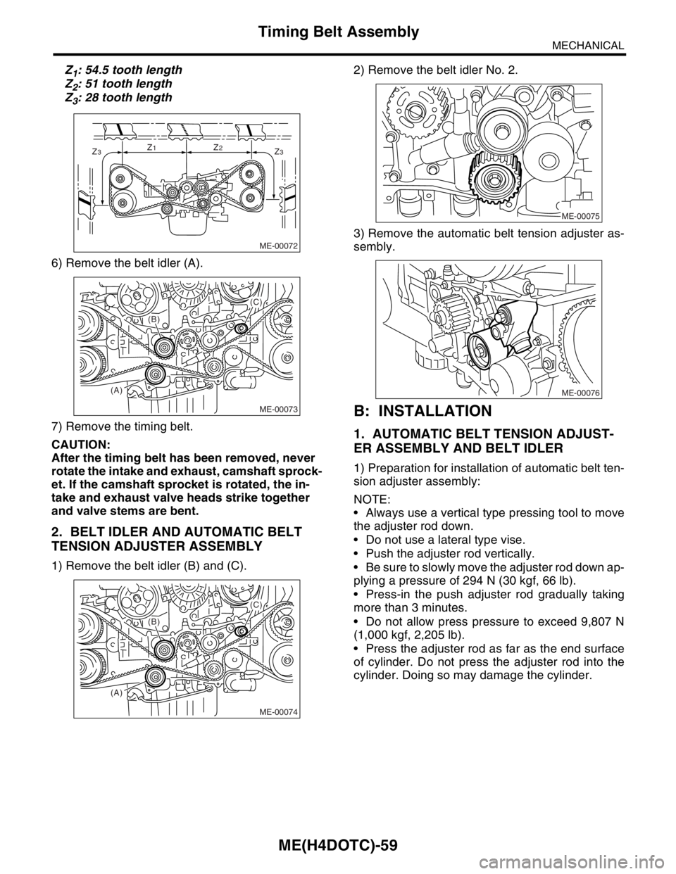
Z1: 54.5 tooth length
Z
2: 51 tooth length
Z
3: 28 tooth length
6) Remove the belt idler (A).
7) Remove the timing belt.
CAUTION:
After the timing belt has been removed, never
rotate the intake and exhaust, camshaft sprock-
et. If the camshaft sprocket is rotated, the in-
take and exhaust valve heads strike together
and valve stems are bent.
2. BELT IDLER AND AUTOMATIC BELT
TENSION ADJUSTER ASSEMBLY
1) Remove the belt idler (B) and (C).2) Remove the belt idler No. 2.
3) Remove the automatic belt tension adjuster as-
sembly.
B: INSTALLATION
1. AUTOMATIC BELT TENSION ADJUST-
ER ASSEMBLY AND BELT IDLER
1) Preparation for installation of automatic belt ten-
sion adjuster assembly:
NOTE:
Always use a vertical type pressing tool to move
the adjuster rod down.
Do not use a lateral type vise.
Push the adjuster rod vertically.
Be sure to slowly move the adjuster rod down ap-
plying a pressure of 294 N (30 kgf, 66 lb).
Press-in the push adjuster rod gradually taking
more than 3 minutes.
Do not allow press pressure to exceed 9,807 N
(1,000 kgf, 2,205 lb).
Press the adjuster rod as far as the end surface
of cylinder. Do not press the adjuster rod into the
cylinder. Doing so may damage the cylinder.
ME-00072
Z3Z1Z2Z3
ME-00073
(A)(B)
(C)
ME-00074
(A)(B)
(C)
ME-00075
ME-00076
Page 1521 of 2870
ME(H4DOTC)-63
MECHANICAL
Timing Belt Assembly
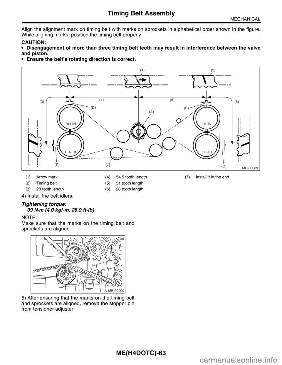
Align the alignment mark on timing belt with marks on sprockets in alphabetical order shown in the figure.
While aligning marks, position the timing belt properly.
CAUTION:
Disengagement of more than three timing belt teeth may result in interference between the valve
and piston.
Ensure the belt’s rotating direction is correct.
4) Install the belt idlers.
Tightening torque:
39 N
⋅m (4.0 kgf-m, 28.9 ft-lb)
NOTE:
Make sure that the marks on the timing belt and
sprockets are aligned.
5) After ensuring that the marks on the timing belt
and sprockets are aligned, remove the stopper pin
from tensioner adjuster.
(1) Arrow mark (4) 54.5 tooth length (7) Install it in the end
(2) Timing belt (5) 51 tooth length
(3) 28 tooth length (6) 28 tooth length
ME-00089 (1) (2)
(5)
(6) (4)
(D)
(A)
(C) (B)
(E) (3)
RH-IN
RH-EXLH-EX LH-IN
(7)
ME-00090
Page 1538 of 2870
ME(H4DOTC)-80
MECHANICAL
Cylinder Head Assembly
(9) Recheck the contact condition between
valve and valve seat after replacing the valve
guide.
4. INTAKE AND EXHAUST VALVE
1) Inspect the flange and stem of valve, and re-
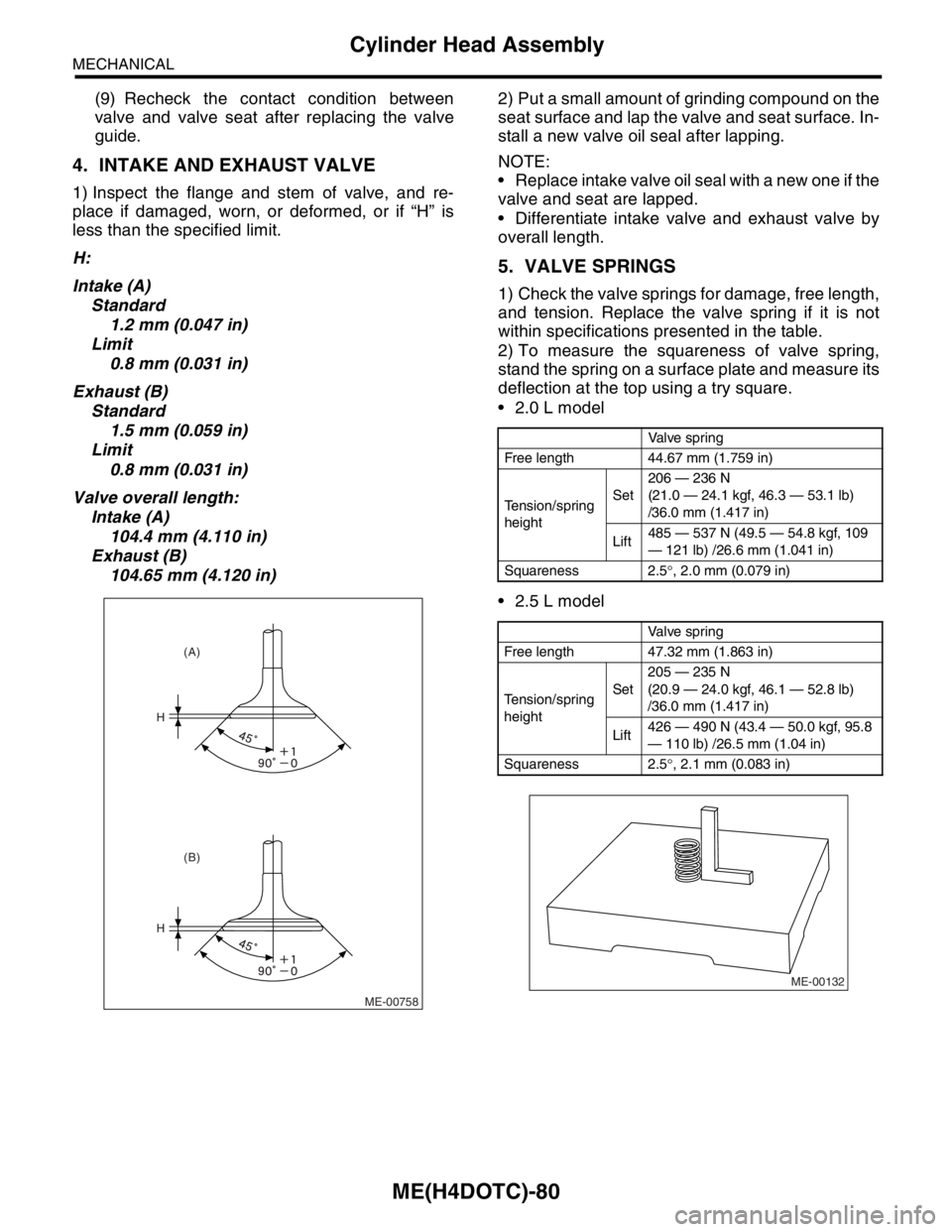
place if damaged, worn, or deformed, or if “H” is
less than the specified limit.
H:
Intake (A)
Standard
1.2 mm (0.047 in)
Limit
0.8 mm (0.031 in)
Exhaust (B)
Standard
1.5 mm (0.059 in)
Limit
0.8 mm (0.031 in)
Valve overall length:
Intake (A)
104.4 mm (4.110 in)
Exhaust (B)
104.65 mm (4.120 in)2) Put a small amount of grinding compound on the
seat surface and lap the valve and seat surface. In-
stall a new valve oil seal after lapping.
NOTE:
Replace intake valve oil seal with a new one if the
valve and seat are lapped.
Differentiate intake valve and exhaust valve by
overall length.
5. VALVE SPRINGS
1) Check the valve springs for damage, free length,
and tension. Replace the valve spring if it is not
within specifications presented in the table.
2) To measure the squareness of valve spring,
stand the spring on a surface plate and measure its
deflection at the top using a try square.
2.0 L model
2.5 L model
ME-00758
H
H
(B) (A)
Valve spring
Free length 44.67 mm (1.759 in)
Tension/spring
heightSet206 — 236 N
(21.0 — 24.1 kgf, 46.3 — 53.1 lb)
/36.0 mm (1.417 in)
Lift485 — 537 N (49.5 — 54.8 kgf, 109
— 121 lb) /26.6 mm (1.041 in)
Squareness 2.5°, 2.0 mm (0.079 in)
Valve spring
Free length 47.32 mm (1.863 in)
Tension/spring
heightSet205 — 235 N
(20.9 — 24.0 kgf, 46.1 — 52.8 lb)
/36.0 mm (1.417 in)
Lift426 — 490 N (43.4 — 50.0 kgf, 95.8
— 110 lb) /26.5 mm (1.04 in)
Squareness 2.5°, 2.1 mm (0.083 in)
ME-00132
Page 1569 of 2870
ME(H4DOTC)-109
MECHANICAL
Cylinder Block
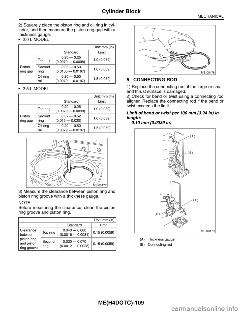
2) Squarely place the piston ring and oil ring in cyl-
inder, and then measure the piston ring gap with a
thickness gauge.
2.0 L MODEL
2.5 L MODEL
3) Measure the clearance between piston ring and
piston ring groove with a thickness gauge.
NOTE:
Before measuring the clearance, clean the piston
ring groove and piston ring.
5. CONNECTING ROD
1) Replace the connecting rod, if the large or small
end thrust surface is damaged.
2) Check for bend or twist using a connecting rod
aligner. Replace the connecting rod if the bend or
twist exceeds the limit.
Limit of bend or twist per 100 mm (3.94 in) in
length:
0.10 mm (0.0039 in)
Unit: mm (in)
Standard Limit
Piston
ring gapTop ring0.20 — 0.25
(0.0079 — 0.0098)1.0 (0.039)
Second
ring0.35 — 0.50
(0.0138 — 0.0197)1.0 (0.039)
Oil ring
rail0.20 — 0.50
(0.0079 — 0.0197)1.5 (0.059)
Unit: mm (in)
Standard Limit
Piston
ring gapTop ring0.20 — 0.25
(0.0079 — 0.0098)1.0 (0.039)
Second
ring0.37 — 0.52
(0.015 — 0.020)1.0 (0.039)
Oil ring
rail0.20 — 0.50
(0.0079 — 0.0197)1.5 (0.059)
Unit: mm (in)
Standard Limit
Clearance
between
piston ring
and piston
ring grooveTop ring0.040 — 0.080
(0.0016 — 0.0031)0.15 (0.0059)
Second
ring0.030 — 0.070
(0.0012 — 0.0028)0.15 (0.0059)
ME-00177
(A) Thickness gauge
(B) Connecting rod
ME-00178
(A)
(A) (B)
(B)
ME-00179
Page 1618 of 2870

IG(H4DOTC)-2
IGNITION
General Description
1. General Description
A: SPECIFICATION
Item Designation
Ignition coil and ignitor
ASSYModel FK0186
Ignition type Direct ignition
Manufacturer DIAMOND
Spark plugType and manufacturer2.0 L model NGK: PFR6G
2.5 L model NGK: ILFR6B
Thread diameter, pitch, length mm 14, 1.25, 26.5
Spark gap mm (in) 0.7 — 0.8 (0.028 — 0.031)
Electrode2.0 L model Platinum
2.5 L model Irigium
Page 1992 of 2870
FU(H4DOTC 2.5)-62
FUEL INJECTION (FUEL SYSTEM)
Fuel Delivery, Return and Evaporation Lines
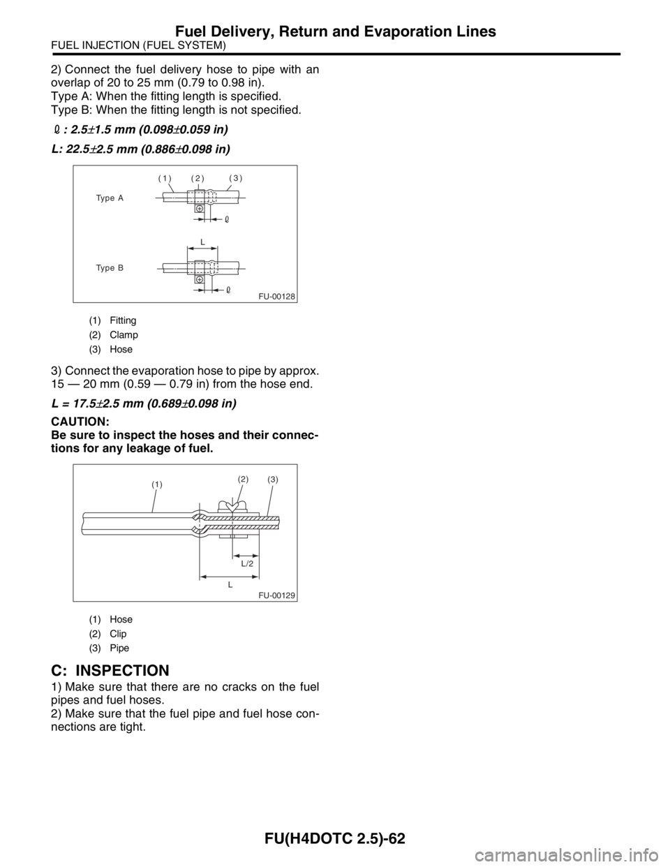
2) Connect the fuel delivery hose to pipe with an
overlap of 20 to 25 mm (0.79 to 0.98 in).
Type A: When the fitting length is specified.
Type B: When the fitting length is not specified.
2: 2.5
±1.5 mm (0.098±0.059 in)
L: 22.5
±2.5 mm (0.886±0.098 in)
3) Connect the evaporation hose to pipe by approx.
15 — 20 mm (0.59 — 0.79 in) from the hose end.
L = 17.5
±2.5 mm (0.689±0.098 in)
CAUTION:
Be sure to inspect the hoses and their connec-
tions for any leakage of fuel.
C: INSPECTION
1) Make sure that there are no cracks on the fuel
pipes and fuel hoses.
2) Make sure that the fuel pipe and fuel hose con-
nections are tight.
(1) Fitting
(2) Clamp
(3) Hose
(1) Hose
(2) Clip
(3) Pipe
FU-00128
(1) (2)(3)
L
Type A
Type B
FU-00129
(1)(2)
L/2
L(3)
Page 2376 of 2870
4AT-63
AUTOMATIC TRANSMISSION
Control Valve Body
B: INSTALLATION
1. NON-TURBO MODEL
1) Set the range select lever in “N” range.
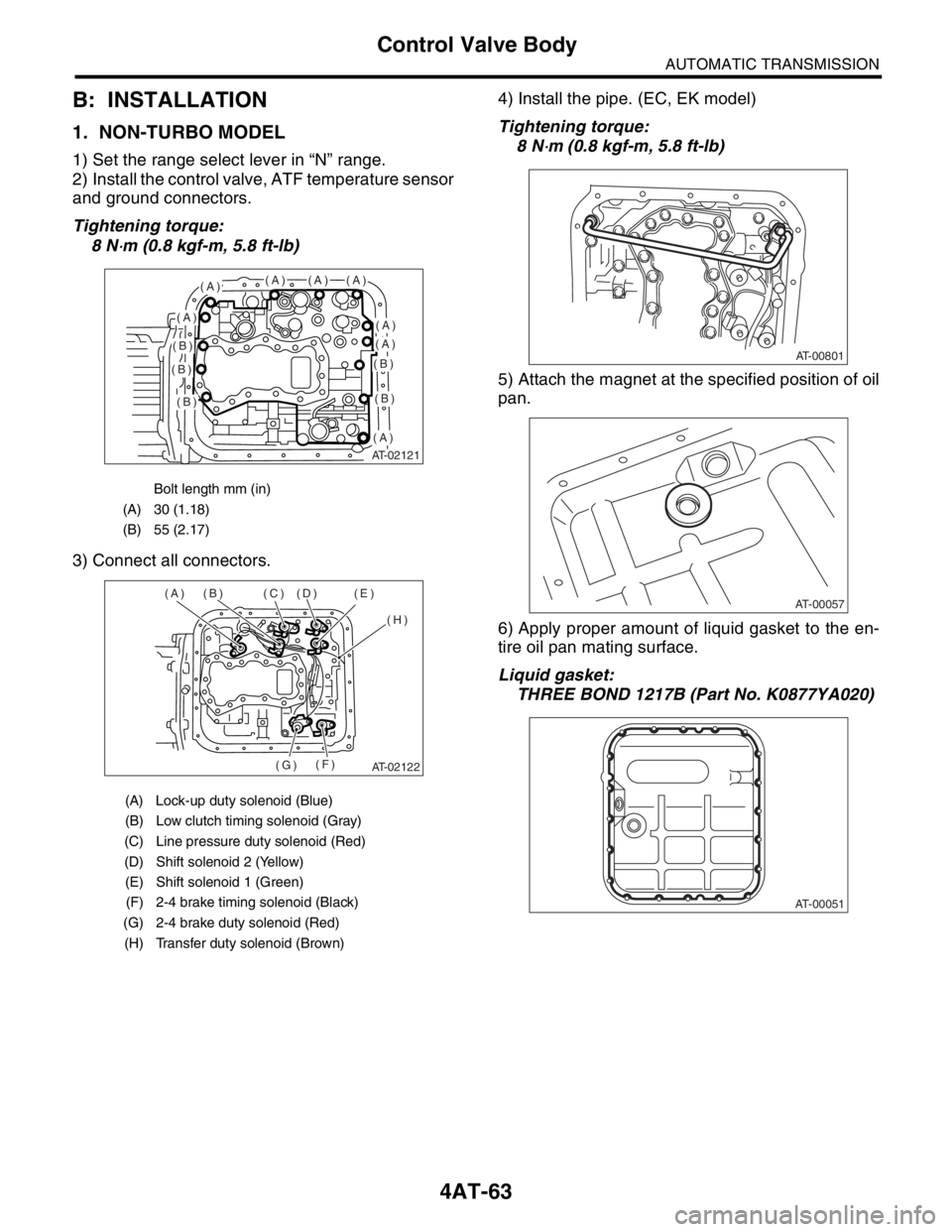
2) Install the control valve, ATF temperature sensor
and ground connectors.
Tightening torque:
8 N
⋅m (0.8 kgf-m, 5.8 ft-lb)
3) Connect all connectors.4) Install the pipe. (EC, EK model)
Tightening torque:
8 N
⋅m (0.8 kgf-m, 5.8 ft-lb)
5) Attach the magnet at the specified position of oil
pan.
6) Apply proper amount of liquid gasket to the en-
tire oil pan mating surface.
Liquid gasket:
THREE BOND 1217B (Part No. K0877YA020)
Bolt length mm (in)
(A) 30 (1.18)
(B) 55 (2.17)
(A) Lock-up duty solenoid (Blue)
(B) Low clutch timing solenoid (Gray)
(C) Line pressure duty solenoid (Red)
(D) Shift solenoid 2 (Yellow)
(E) Shift solenoid 1 (Green)
(F) 2-4 brake timing solenoid (Black)
(G) 2-4 brake duty solenoid (Red)
(H) Transfer duty solenoid (Brown)
AT-02121
(A)(A)(A)(A)
(A)(A)
(A)
(A)
(B)
(B)
(B)
(B)
(B)
AT-02122
(A) (B) (C) (D) (E)
(H)
(F)
(G)
AT-00801
AT-00057
AT-00051