oxygen SUBARU FORESTER 2004 Service Manual PDF
[x] Cancel search | Manufacturer: SUBARU, Model Year: 2004, Model line: FORESTER, Model: SUBARU FORESTER 2004Pages: 2870, PDF Size: 38.67 MB
Page 1353 of 2870

EN(H4SO)-255
ENGINE (DIAGNOSTIC)
General Diagnostic Table
20.General Diagnostic Table
A: INSPECTION
1. ENGINE
NOTE:
Malfunction of parts other than those listed is also possible.
Symptom Problem parts
1. Engine stalls during idling.1) Idle air control solenoid valve
2) Manifold absolute pressure sensor
3) Intake air temperature sensor
4) Ignition parts (*1)
5) Engine coolant temperature sensor (*2)
6) Crankshaft position sensor (*3)
7) Camshaft position sensor (*3)
8) Fuel injection parts (*4)
2. Rough idling1) Idle air control solenoid valve
2) Manifold absolute pressure sensor
3) Intake air temperature sensor
4) Engine coolant temperature sensor (*2)
5) Ignition parts (*1)
6) Air intake system (*5)
7) Fuel injection parts (*4)
8) Throttle position sensor
9) Crankshaft position sensor (*3)
10) Camshaft position sensor (*3)
11) Oxygen sensor
12) Fuel pump and fuel pump relay
3. Engine does not return to idle.1) Idle air control solenoid valve
2) Engine coolant temperature sensor
3) Accelerator cable (*6)
4) Throttle position sensor
5) Manifold absolute pressure sensor
6) Intake air temperature sensor
4. Poor acceleration1) Manifold absolute pressure sensor
2) Intake air temperature sensor
3) Throttle position sensor
4) Fuel injection parts (*4)
5) Fuel pump and fuel pump relay
6) Engine coolant temperature sensor (*2)
7) Crankshaft position sensor (*3)
8) Camshaft position sensor (*3)
9) A/C switch and A/C cut relay
10) Engine torque control signal circuit
11) Ignition parts (*1)
5. Engine stalls or engine sags or hesitates at
acceleration.1) Manifold absolute pressure sensor
2) Intake air temperature sensor
3) Engine coolant temperature sensor (*2)
4) Crankshaft position sensor (*3)
5) Camshaft position sensor (*3)
6) Purge control solenoid valve
7) Fuel injection parts (*4)
8) Throttle position sensor
9) Fuel pump and fuel pump relay
Page 1356 of 2870

FUEL INJECTION (FUEL SYSTEM)
FU(H4DOTC)
Page
1. General Description ....................................................................................2
2. Throttle Body .............................................................................................13
3. Intake Manifold ..........................................................................................14
4. Engine Coolant Temperature Sensor........................................................29
5. Crankshaft Position Sensor.......................................................................30
6. Camshaft Position Sensor.........................................................................31
7. AVCS Camshaft Position Sensor ..............................................................32
8. Knock Sensor ............................................................................................33
9. Throttle Position Sensor ............................................................................34
10. Mass Air Flow and Intake Air Temperature Sensor ..................................35
11. Manifold Absolute Pressure Sensor ..........................................................36
12. Idle Air Control Solenoid Valve .................................................................37
13. Fuel Injector ..............................................................................................38
14. Tumble Generator Valve Assembly ..........................................................42
15. Tumble Generator Valve Actuator.............................................................43
16. Wastegate Control Solenoid Valve Assembly ...........................................44
17. Front Oxygen (A/F) Sensor .......................................................................45
18. Rear Oxygen Sensor.................................................................................47
19. Exhaust Temperature Sensor ...................................................................49
20. Engine Control Module (ECM) ..................................................................50
21. Main Relay ................................................................................................51
22. Fuel Pump Relay.......................................................................................52
23. Fuel Pump Control Unit .............................................................................53
24. Fuel ...........................................................................................................54
25. Fuel Tank ..................................................................................................55
26. Fuel Filler Pipe ..........................................................................................58
27. Fuel Pump .................................................................................................62
28. Fuel Level Sensor .....................................................................................64
29. Fuel Sub Level Sensor ..............................................................................65
30. Fuel Filter ..................................................................................................67
31. Fuel Cut Valve...........................................................................................68
32. Fuel Damper Valve ...................................................................................69
33. Fuel Delivery, Return and Evaporation Lines............................................70
34. Fuel System Trouble in General ...............................................................73
Page 1400 of 2870
FU(H4DOTC)-45
FUEL INJECTION (FUEL SYSTEM)
Front Oxygen (A/F) Sensor
17.Front Oxygen (A/F) Sensor
A: REMOVAL
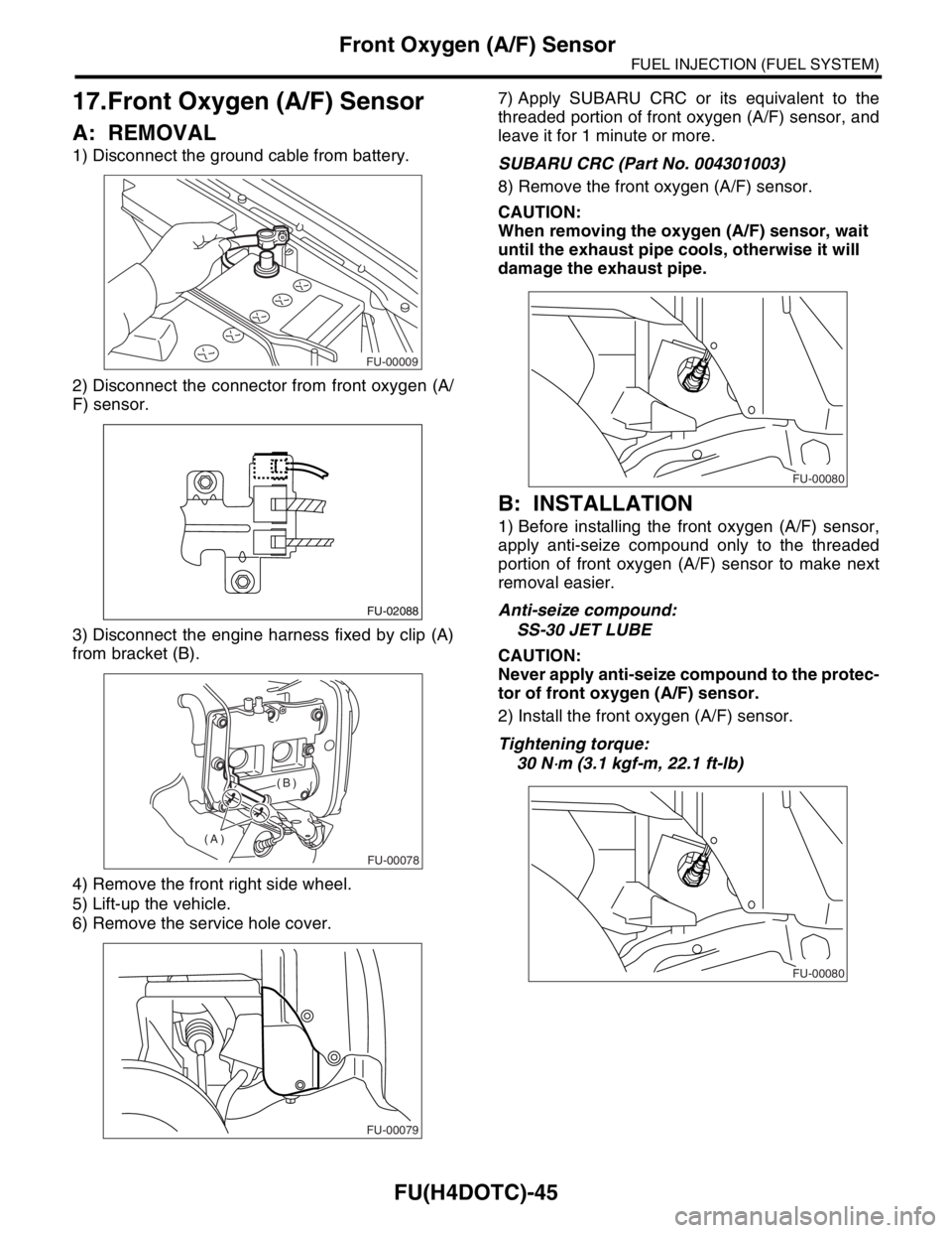
1) Disconnect the ground cable from battery.
2) Disconnect the connector from front oxygen (A/
F) sensor.
3) Disconnect the engine harness fixed by clip (A)
from bracket (B).
4) Remove the front right side wheel.
5) Lift-up the vehicle.
6) Remove the service hole cover.7) Apply SUBARU CRC or its equivalent to the
threaded portion of front oxygen (A/F) sensor, and
leave it for 1 minute or more.
SUBARU CRC (Part No. 004301003)
8) Remove the front oxygen (A/F) sensor.
CAUTION:
When removing the oxygen (A/F) sensor, wait
until the exhaust pipe cools, otherwise it will
damage the exhaust pipe.
B: INSTALLATION
1) Before installing the front oxygen (A/F) sensor,
apply anti-seize compound only to the threaded
portion of front oxygen (A/F) sensor to make next
removal easier.
Anti-seize compound:
SS-30 JET LUBE
CAUTION:
Never apply anti-seize compound to the protec-
tor of front oxygen (A/F) sensor.
2) Install the front oxygen (A/F) sensor.
Tightening torque:
30 N
⋅m (3.1 kgf-m, 22.1 ft-lb)
FU-00009
FU-02088
FU-00078
(A)(B)
FU-00079
FU-00080
FU-00080
Page 1401 of 2870
FU(H4DOTC)-46
FUEL INJECTION (FUEL SYSTEM)
Front Oxygen (A/F) Sensor
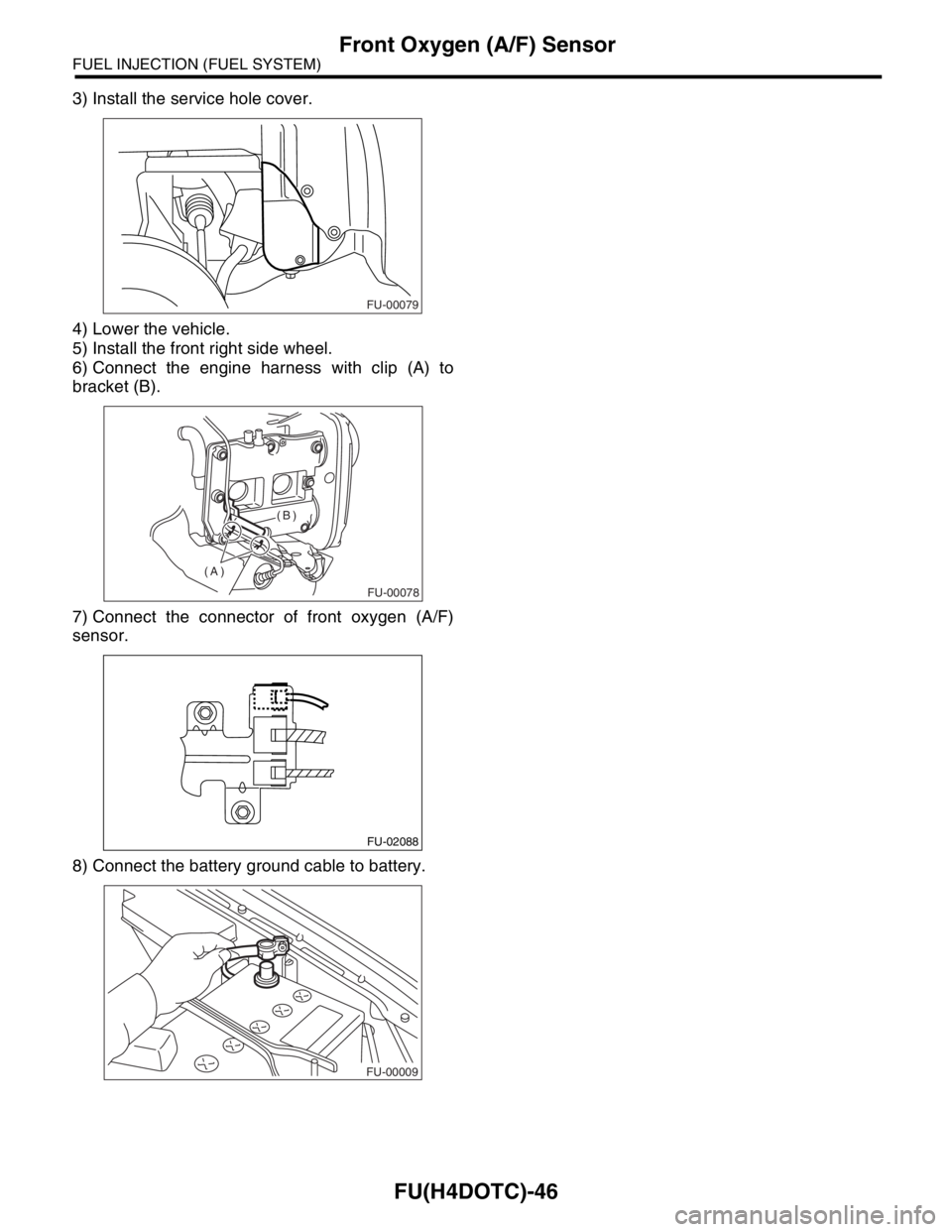
3) Install the service hole cover.
4) Lower the vehicle.
5) Install the front right side wheel.
6) Connect the engine harness with clip (A) to
bracket (B).
7) Connect the connector of front oxygen (A/F)
sensor.
8) Connect the battery ground cable to battery.
FU-00079
FU-00078
(A)(B)
FU-02088
FU-00009
Page 1402 of 2870
FU(H4DOTC)-47
FUEL INJECTION (FUEL SYSTEM)
Rear Oxygen Sensor
18.Rear Oxygen Sensor
A: REMOVAL
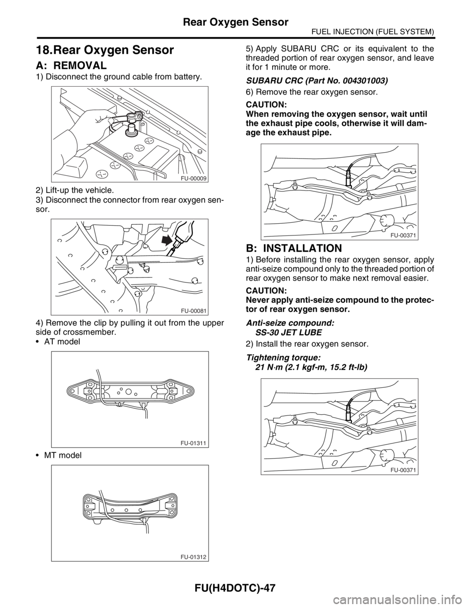
1) Disconnect the ground cable from battery.
2) Lift-up the vehicle.
3) Disconnect the connector from rear oxygen sen-
sor.
4) Remove the clip by pulling it out from the upper
side of crossmember.
AT model
MT model5) Apply SUBARU CRC or its equivalent to the
threaded portion of rear oxygen sensor, and leave
it for 1 minute or more.
SUBARU CRC (Part No. 004301003)
6) Remove the rear oxygen sensor.
CAUTION:
When removing the oxygen sensor, wait until
the exhaust pipe cools, otherwise it will dam-
age the exhaust pipe.
B: INSTALLATION
1) Before installing the rear oxygen sensor, apply
anti-seize compound only to the threaded portion of
rear oxygen sensor to make next removal easier.
CAUTION:
Never apply anti-seize compound to the protec-
tor of rear oxygen sensor.
Anti-seize compound:
SS-30 JET LUBE
2) Install the rear oxygen sensor.
Tightening torque:
21 N
⋅m (2.1 kgf-m, 15.2 ft-lb)
FU-00009
FU-00081
FU-01311
FU-01312
FU-00371
FU-00371
Page 1403 of 2870
FU(H4DOTC)-48
FUEL INJECTION (FUEL SYSTEM)
Rear Oxygen Sensor
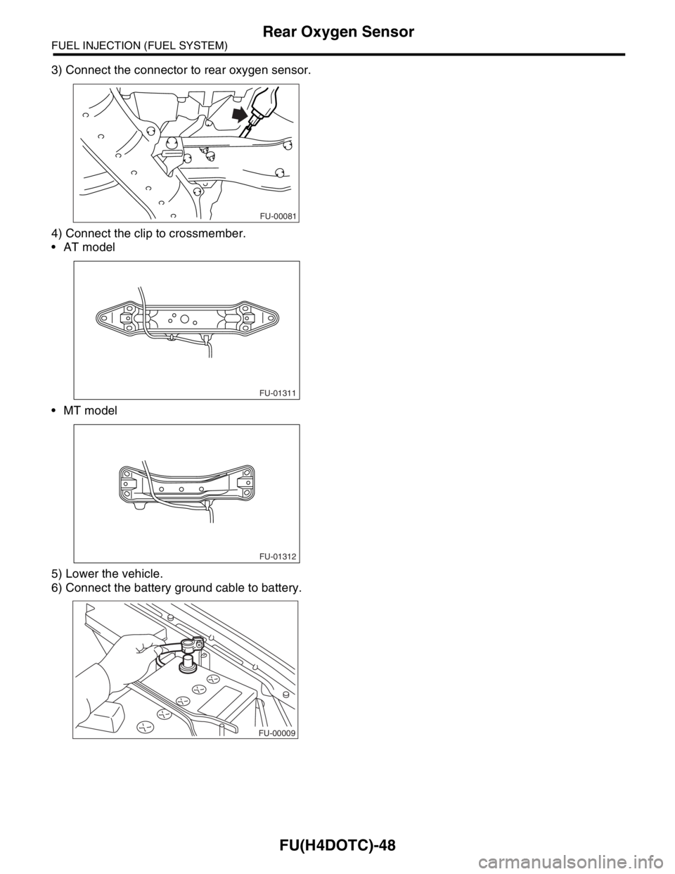
3) Connect the connector to rear oxygen sensor.
4) Connect the clip to crossmember.
AT model
MT model
5) Lower the vehicle.
6) Connect the battery ground cable to battery.
FU-00081
FU-01311
FU-01312
FU-00009
Page 1589 of 2870

EX(H4DOTC)-3
EXHAUST
General Description
(1) Gasket (12) Exhaust manifold upper cover
(LH)Tightening torque: N·m (kgf-m, ft-lb)
(2) Exhaust manifold upper cover
(RH)T1: 19 (1.9, 13.7)
(13) Exhaust manifold lower cover (LH)T2: 7.5 (0.8, 5.5)
(3) Exhaust manifold (RH) (14) GasketT3: 35 (3.6, 26.0)
(4) Exhaust manifold lower cover
(RH)(15) Turbocharger joint pipeT4: 40 (4, 28.9)
(16) GasketT5:
(A/F) Sensor.> or
INSTALLATION, Front Oxygen
(A/F) Sensor.> (5) Front exhaust pipe upper cover (17) Front oxygen (A/F) sensor
(6) Front exhaust pipe upper insulator
(RH)(18) Exhaust temperature sensor
(19) Precatalytic converter
(7) Gasket (20) Front exhaust pipe upper insulator
(LH)
(8) Front exhaust pipeT6:
Temperature Sensor.> or
INSTALLATION, Exhaust
Temperature Sensor.> (9) Front exhaust pipe lower insulator
(RH)(21) Front exhaust pipe lower insulator
(LH)
(10) Front exhaust pipe lower cover (22) Exhaust manifold (LH)
(11) Gasket
Page 1590 of 2870
EX(H4DOTC)-4
EXHAUST
General Description
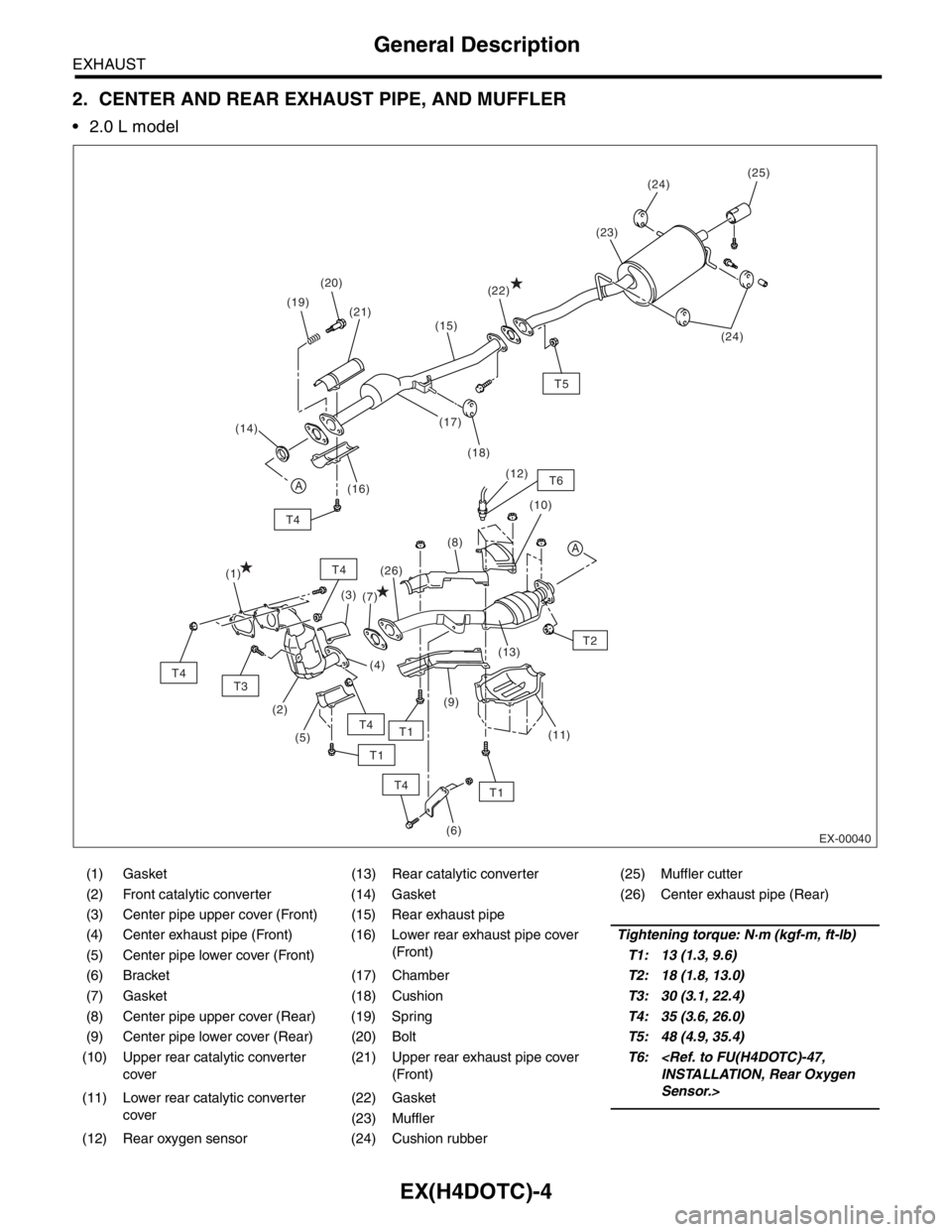
2. CENTER AND REAR EXHAUST PIPE, AND MUFFLER
2.0 L model
(1) Gasket (13) Rear catalytic converter (25) Muffler cutter
(2) Front catalytic converter (14) Gasket (26) Center exhaust pipe (Rear)
(3) Center pipe upper cover (Front) (15) Rear exhaust pipe
(4) Center exhaust pipe (Front) (16) Lower rear exhaust pipe cover
(Front)Tightening torque: N·m (kgf-m, ft-lb)
(5) Center pipe lower cover (Front)T1: 13 (1.3, 9.6)
(6) Bracket (17) ChamberT2: 18 (1.8, 13.0)
(7) Gasket (18) CushionT3: 30 (3.1, 22.4)
(8) Center pipe upper cover (Rear) (19) SpringT4: 35 (3.6, 26.0)
(9) Center pipe lower cover (Rear) (20) BoltT5: 48 (4.9, 35.4)
(10) Upper rear catalytic converter
cover(21) Upper rear exhaust pipe cover
(Front)T6:
Sensor.>
(11) Lower rear catalytic converter
cover(22) Gasket
(23) Muffler
(12) Rear oxygen sensor (24) Cushion rubber
EX-00040
T4
A
T1
T5
T6
T4
(25)
(19)(24)
(24) (20)
(18) (17)
(16)(23)
(22)
(21)
A
(14)
T3
T4
T4
T4
(1)
(2)
(6)
(3)
(5)
T2 (8)(10) (12)
(11) (13)
(9) (26)
(7)
T1
T1
(15)
(4)
Page 1591 of 2870
EX(H4DOTC)-5
EXHAUST
General Description
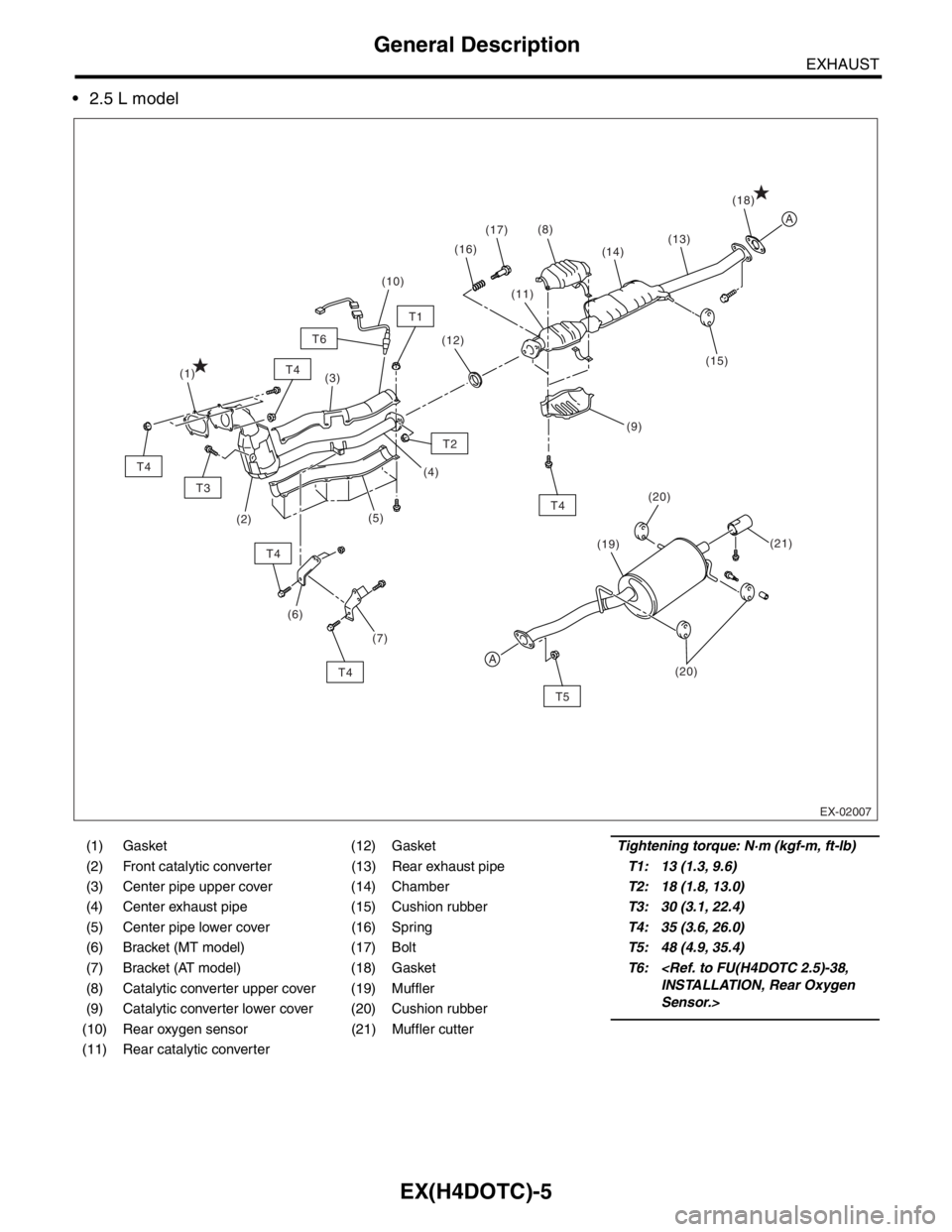
2.5 L model
(1) Gasket (12) GasketTightening torque: N·m (kgf-m, ft-lb)
(2) Front catalytic converter (13) Rear exhaust pipeT1: 13 (1.3, 9.6)
(3) Center pipe upper cover (14) ChamberT2: 18 (1.8, 13.0)
(4) Center exhaust pipe (15) Cushion rubberT3: 30 (3.1, 22.4)
(5) Center pipe lower cover (16) SpringT4: 35 (3.6, 26.0)
(6) Bracket (MT model) (17) BoltT5: 48 (4.9, 35.4)
(7) Bracket (AT model) (18) GasketT6:
Sensor.> (8) Catalytic converter upper cover (19) Muffler
(9) Catalytic converter lower cover (20) Cushion rubber
(10) Rear oxygen sensor (21) Muffler cutter
(11) Rear catalytic converter
A
A
T5
T4
T3
T4
T4
T4
T4
T2
(21) (20)
(19)(18)
(15) (14)
(1)
(2)(3)
(5)
(6)(4)(11) (17)
(16)(8)
(12)
(10)
(13)
T1
T6
(7)
EX-02007
(9)
(20)
Page 1593 of 2870
EX(H4DOTC)-7
EXHAUST
Front Exhaust Pipe
2. Front Exhaust Pipe
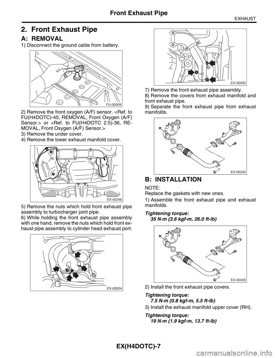
A: REMOVAL
1) Disconnect the ground cable from battery.
2) Remove the front oxygen (A/F) sensor.
Sensor.> or
3) Remove the under cover.
4) Remove the lower exhaust manifold cover.
5) Remove the nuts which hold front exhaust pipe
assembly to turbocharger joint pipe.
6) While holding the front exhaust pipe assembly
with one hand, remove the nuts which hold front ex-
haust pipe assembly to cylinder head exhaust port.7) Remove the front exhaust pipe assembly.
8) Remove the covers from exhaust manifold and
front exhaust pipe.
9) Separate the front exhaust pipe from exhaust
manifolds.
B: INSTALLATION
NOTE:
Replace the gaskets with new ones.
1) Assemble the front exhaust pipe and exhaust
manifolds.
Tightening torque:
35 N·m (3.6 kgf-m, 26.0 ft-lb)
2) Install the front exhaust pipe covers.
Tightening torque:
7.5 N·m (0.8 kgf-m, 5.5 ft-lb)
3) Install the exhaust manifold upper cover (RH).
Tightening torque:
19 N·m (1.9 kgf-m, 13.7 ft-lb)
FU-00009
EX-00246
EX-00004
EX-00005
EX-00245
EX-00245