ECM IO Signal SUBARU FORESTER 2004 Service Repair Manual
[x] Cancel search | Manufacturer: SUBARU, Model Year: 2004, Model line: FORESTER, Model: SUBARU FORESTER 2004Pages: 2870, PDF Size: 38.67 MB
Page 74 of 2870

AC-18
HVAC SYSTEM (AUTO A/C)(DIAGNOSTIC)
Diagnostics for A/C System Malfunction
Step Check Yes No
1 CHECK FUSE.
1) Turn the ignition switch to OFF.
2) Remove the main fan fuse and sub fan fuse
in main fuse box.
3) Check the condition of fuse.Is the fuse blown out? Replace the fuse. Go to step 2.
2 CHECK THE POWER SUPPLY TO PRES-
SURE SWITCH.
1) Disconnect the connector from pressure
switch.
2) Turn the ignition switch to ON.
3) Measure the voltage between harness con-
nector and chassis ground.
Connector & terminal
(F79) No. 1 (+) — Chassis ground (
−):Is the voltage more than 10 V? Go to step 3.Repair the har-
ness for pressure
switch power sup-
ply circuit.
3 CHECK THE HARNESS BETWEEN PRES-
SURE SWITCH AND A/C RELAY HARNESS.
1) Turn the ignition switch to OFF.
2) Remove the A/C relay in the main fuse box.
3) Measure the resistance between A/C relay
and pressure switch connector.
Connector & terminal
(F27) No. 17 — (F79) No. 2:Is the resistance less than 1
Ω?Go to step 4.Repair the har-
ness between A/C
relay and pres-
sure switch.
4 CHECK THE PRESSURE SWITCH.
Measure the resistance between pressure
switch terminals.
Te r m i n a l s
No. 1 — No. 2:Is the resistance less than 1
Ω?Go to step 5.Replace the pres-
sure switch.
5 CHECK THE A/C CUT SIGNAL CIRCUIT.
1) Disconnect the connector from auto A/C
control module.
2) Measure the resistance between auto A/C
control module and pressure switch connector.
Connector & terminal
(i48) No. 10 — (F79) No. 2:Is the resistance less than 1
Ω?Go to step 6.Repair the har-
ness between auto
A/C control mod-
ule and pressure
switch.
6 CHECK THE A/C ON SIGNAL CIRCUIT.
1) Disconnect the connector from ECM.
2) Measure the resistance between ECM and
auto A/C control module connector.
Connector & terminal
Turbo model
(B137) No. 17 — (i49) No. 17:
Non-turbo model
(B136) No. 11 — (i49) No. 17:Is the resistance less than 1
Ω?Go to step 7.Repair the har-
ness between auto
A/C control mod-
ule and ECM.
7 CHECK A/C RELAY.
1) Remove the A/C relay in main fuse box.
2) Check the A/C relay.
OK?Go to step 8.Replace the A/C
relay.
8 CHECK POWER SUPPLY TO MAGNET
CLUTCH OF A/C COMPRESSOR.
1) Turn the ignition switch to OFF, and then
connect the A/C relay connector and all
removed connectors.
2) Start the engine, and turn A/C switch to
ON.
3) Set the temperature control dial to maxi-
mum cold position.
4) Measure the voltage between magnet
clutch harness connector and chassis ground.
Connector & terminal
(F24) No. 1 (+) — Chassis ground (
−):Is the voltage more than 10.5 V
(at normal temperature)?Go to step 9.Repair the har-
ness for power
supply line of A/C
compressor.
Page 391 of 2870

IDI-7
INSTRUMENTATION/DRIVER INFO
Combination Meter System
5. CHECK ENGINE CONTROL MODULE (ECM)
6. CHECK FUEL LEVEL SENSOR
Step Check Yes No
1 CHECK ECM SIGNAL.
1) Start the engine.
2) Measure the voltage between ECM con-
nector and engine ground.
Connector & terminal
Non-turbo model
(B134) No. 10 (+) — Engine ground (
−):
Turbo model
(B134) No. 23 (+) — Engine ground (
−):Is the voltage 0 V ← → 14 V? Go to step 2.Check ECM.
Basic Diagnostics
Procedure.>
Basic Diagnostics
Procedure.>
2 CHECK HARNESS BETWEEN COMBINA-
TION METER AND ECM.
1) Turn the ignition switch to OFF.
2) Disconnect the connector from ECM and
combination meter.
3) Measure the resistance between ECM har-
ness connector and combination meter har-
ness connector.
Connector & terminal
Non-turbo model
(B134) No. 10 — (i10) No. 11:
Turbo model
(B134) No. 23 — (i10) No. 11:Is the resistance less than 10
Ω?Check the tachom-
eter.
Tachometer.>Repair the wiring
harness.
Step Check Yes No
1 CHECK FUEL LEVEL SENSOR.
1) Remove the fuel level sensor.
sor.>
2) Measure the resistance between fuel level
sensor terminals when setting the float to
FULL and EMPTY position.
Te r m i n a l s
No. 3 — No. 5:Is the resistance 0.5 to 2.5 Ω
(FULL) and 50 to 52 Ω
(EMPTY)?Go to step 2.Replace the fuel
level sensor.
2 CHECK FUEL SUB LEVEL SENSOR.
1) Remove the fuel sub level sensor.
Sensor.>
2) Measure the resistance between fuel sub
level sensor terminals when setting the float to
FULL and EMPTY position.
Te r m i n a l s
No. 1 — No. 2:Is the resistance 0.5 to 2.5 Ω
(FULL) and 42 to 44 Ω
(EMPTY)?Go to step 3.Replace the fuel
sub level sensor.
3 CHECK HARNESS BETWEEN FUEL SUB
LEVEL SENSOR AND COMBINATION
METER.
1) Disconnect the connector from combination
meter.
2) Measure the resistance between fuel sub
level sensor harness connector terminal and
combination meter harness connector termi-
nal.
Connector & terminal
(R59) No. 1 — (i11) No. 1:Is the resistance less than 10
Ω?Go to step 4.Repair the wiring
harness.
Page 613 of 2870

CRUISE CONTROL SYSTEM
(DIAGNOSTIC)
CC(H4DOTC 2.5)
Page
1. Basic Diagnostic Procedure ........................................................................2
2. General Description ....................................................................................4
3. Electrical Components Location..................................................................5
4. Engine Control Module (ECM) I/O Signal ...................................................6
5. Subaru Select Monitor.................................................................................8
6. Diagnostic Procedure with Symptom ........................................................10
7. List of Diagnostic Trouble Code (DTC) .....................................................13
8. Diagnostic Procedure with Diagnostic Trouble Code (DTC) .....................16
Page 618 of 2870
CC(H4DOTC 2.5)-6
CRUISE CONTROL SYSTEM (DIAGNOSTIC)
Engine Control Module (ECM) I/O Signal
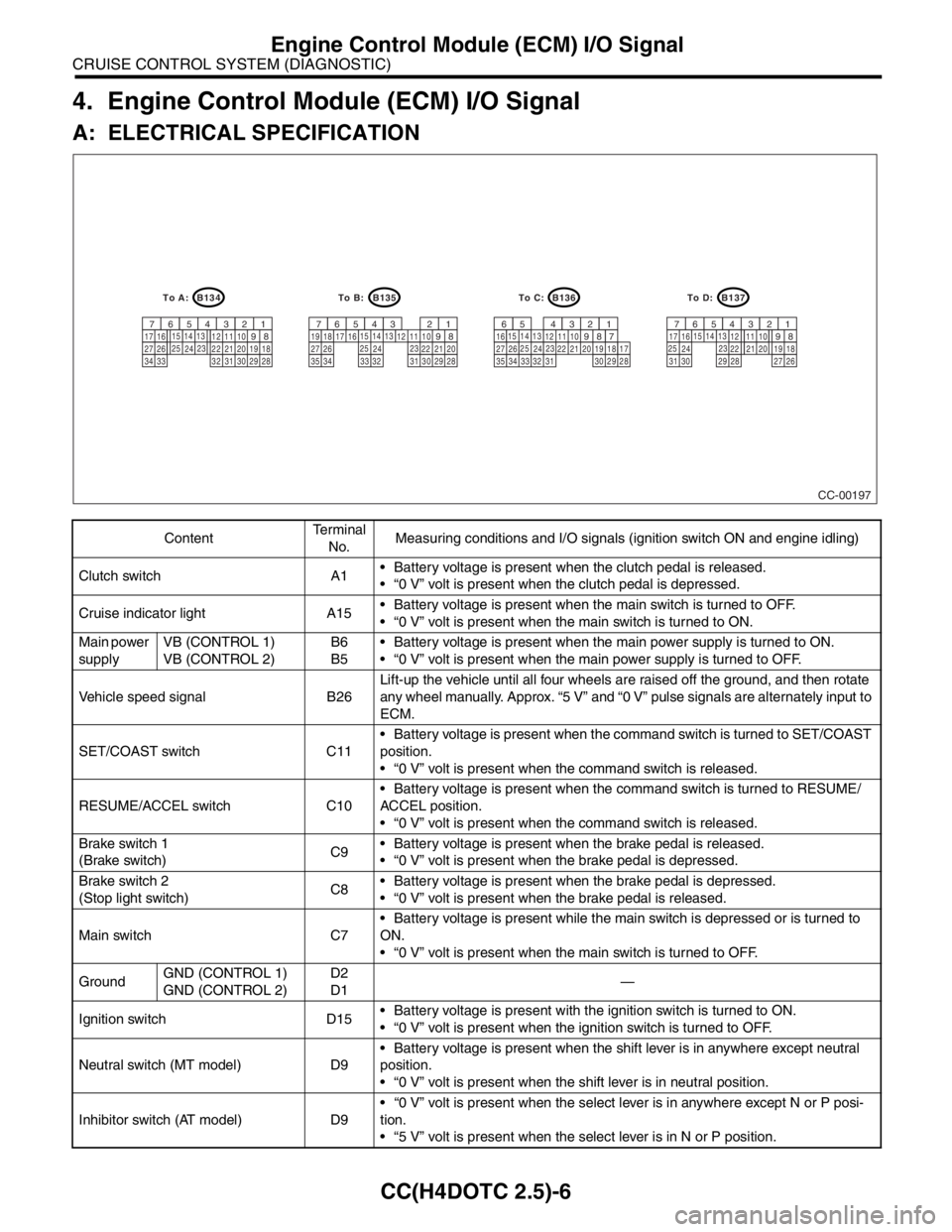
4. Engine Control Module (ECM) I/O Signal
A: ELECTRICAL SPECIFICATION
ContentTe r m i n a l
No.Measuring conditions and I/O signals (ignition switch ON and engine idling)
Clutch switch A1 Battery voltage is present when the clutch pedal is released.
“0 V” volt is present when the clutch pedal is depressed.
Cruise indicator light A15 Battery voltage is present when the main switch is turned to OFF.
“0 V” volt is present when the main switch is turned to ON.
Main power
supplyVB (CONTROL 1)
VB (CONTROL 2)B6
B5 Battery voltage is present when the main power supply is turned to ON.
“0 V” volt is present when the main power supply is turned to OFF.
Vehicle speed signal B26Lift-up the vehicle until all four wheels are raised off the ground, and then rotate
any wheel manually. Approx. “5 V” and “0 V” pulse signals are alternately input to
ECM.
SET/COAST switch C11 Battery voltage is present when the command switch is turned to SET/COAST
position.
“0 V” volt is present when the command switch is released.
RESUME/ACCEL switch C10 Battery voltage is present when the command switch is turned to RESUME/
ACCEL position.
“0 V” volt is present when the command switch is released.
Brake switch 1
(Brake switch)C9 Battery voltage is present when the brake pedal is released.
“0 V” volt is present when the brake pedal is depressed.
Brake switch 2
(Stop light switch)C8 Battery voltage is present when the brake pedal is depressed.
“0 V” volt is present when the brake pedal is released.
Main switch C7 Battery voltage is present while the main switch is depressed or is turned to
ON.
“0 V” volt is present when the main switch is turned to OFF.
GroundGND (CONTROL 1)
GND (CONTROL 2)D2
D1—
Ignition switch D15 Battery voltage is present with the ignition switch is turned to ON.
“0 V” volt is present when the ignition switch is turned to OFF.
Neutral switch (MT model) D9 Battery voltage is present when the shift lever is in anywhere except neutral
position.
“0 V” volt is present when the shift lever is in neutral position.
Inhibitor switch (AT model) D9 “0 V” volt is present when the select lever is in anywhere except N or P posi-
tion.
“5 V” volt is present when the select lever is in N or P position.
CC-00197
B134
9
30 29 28 32 3120 19 18 22 2110 12 1114
24
34 3327 2617 16123456713
23 15
258
B135
9
30 29 28
323120 22 2110 12 1114
24
35
3327 2617 16123456713
23 15
258
B136
9
30 29 28
32 3120 19 18 22 2110 12 1114
24
34 3327 261612345613
23 15
258
B137
9
29 2820 19 18 22
2110 12
1114
2417 16123456713
23 15
2581819
34
7173530 3127 26
To D: To C: To B: To A:
Page 619 of 2870

CC(H4DOTC 2.5)-7
CRUISE CONTROL SYSTEM (DIAGNOSTIC)
Engine Control Module (ECM) I/O Signal
B: WIRING DIAGRAM
Page 620 of 2870
CC(H4DOTC 2.5)-8
CRUISE CONTROL SYSTEM (DIAGNOSTIC)
Subaru Select Monitor
5. Subaru Select Monitor
A: OPERATION
1. GENERAL
The on-board diagnosis function of the cruise con-
trol system uses the Subaru Select Monitor.
The on-board diagnosis function operates in two
categories, which are used depending on the type
of problems;
1) Cruise cancel conditions diagnosis:
(1) This category of diagnosis requires actual ve-
hicle driving in order to determine the cause, (as
when cruise speed is cancelled during driving al-
though cruise cancel condition is not entered).
(2) Cruise control memory of ECM stores the
cancel condition (Code No.) which occurred dur-
ing driving. When there are plural cancel condi-
tions (Code No.), they are shown on the Subaru
Select Monitor.
CAUTION:
The cruise control memory stores not only the
cruise “cancel” which occurred (although “can-
cel” operation is not entered by the driver), but
also the “cancel” condition input by the driver.
The content of memory is cleared when igni-
tion switch or cruise main switch is turned OFF.
2) Real-time diagnosis:
The real-time diagnosis function is used to deter-
mine whether or not the input signal system is in
good order, according to signal emitted from
switches, sensors, etc.
(1) Vehicle cannot be driven at cruise speed be-
cause problem occurs in the cruise control sys-
tem or its associated circuits.
(2) Monitor the signal conditions from switches
and sensors.
2. CRUISE CANCEL CONDITIONS DIAG-
NOSIS
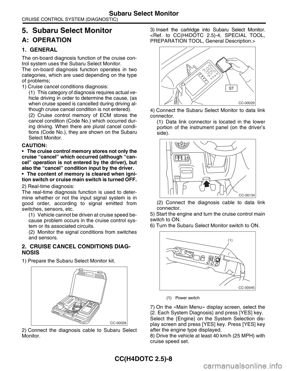
1) Prepare the Subaru Select Monitor kit.
2) Connect the diagnosis cable to Subaru Select
Monitor.3) Insert the cartridge into Subaru Select Monitor.
4) Connect the Subaru Select Monitor to data link
connector.
(1) Data link connector is located in the lower
portion of the instrument panel (on the driver’s
side).
(2) Connect the diagnosis cable to data link
connector.
5) Start the engine and turn the cruise control main
switch to ON.
6) Turn the Subaru Select Monitor switch to ON.
7) On the «Main Menu» display screen, select the
{2. Each System Diagnosis} and press [YES] key.
Select the {Engine} on the System Selection dis-
play screen and press [YES] key. Press [YES] key
after the engine type displayed.
8) Drive the vehicle at least 40 km/h (25 MPH) with
cruise speed set.
CC-00028
(1) Power switch
CC-00029
CC-00134
CC-00045
(1)
Page 626 of 2870

CC(H4DOTC 2.5)-14
CRUISE CONTROL SYSTEM (DIAGNOSTIC)
List of Diagnostic Trouble Code (DTC)
21 Cruise control switch is
abnormal when the igni-
tion switch is turned to ON.Each switch of cruise control command switch has
already been ON when the ignition switch is turned to
ON.This DTC is indicated
without operating the main
switch.
DTC 11, 15, 21 AND 24
CRUISE CONTROL
COMMAND SWITCH,
Diagnostic Procedure with
Diagnostic Trouble Code
(DTC).>
22 Vehicle speed variation is
abnormal.Abnormality of vehicle speed variation is detected.
VEHICLE SPEED SEN-
SOR, Diagnostic Proce-
dure with Diagnostic
Trouble Code (DTC).>
23 Engine-related sensor is
abnormal.Abnormality related to engine is detected.
Procedure.>
24 Cruise control-related
switch is abnormal.Abnormality of command switch is detected. (Open cir-
cuit is detected when continuing to be ON for an
extremely long time [approx. two minutes].)This DTC is indicated with
normal operation.
DTC 11, 15, 21 AND 24
CRUISE CONTROL
COMMAND SWITCH,
Diagnostic Procedure with
Diagnostic Trouble Code
(DTC).>
25 Brake switch input circuit
is abnormal.Abnormality of brake switch input circuit in ECM is
detected.
STOP LIGHT SWITCH
AND BRAKE SWITCH,
Diagnostic Procedure with
Diagnostic Trouble Code
(DTC).>
26 Engine speed signal. Abnormal increase of engine speed is detected.
Gear is shifted to neutral, 1st or reverse position.Cruise with more than 2nd
shift position.
32 Out of vehicle speed range
of cruise control operation. Vehicle speed becomes under the control limit during
cruise driving.
Set operation is conducted out of vehicle speed range
for setting
RESUME operation is conducted without vehicle
speed memory.This DTC is also indicated
when increasing the
speed to the cruise set
available vehicle speed
and conducting the set
operation again.
DTC 22 AND 32 VEHICLE
SPEED SENSOR, Diag-
nostic Procedure with
Diagnostic Trouble Code
(DTC).>
33 Prohibition of WAIT after
acceleration operation.Vehicle speed becomes over the control limit during
cruise driving.This DTC is indicated
when running at the high
speed which is not suit-
able for cruise control. In
this case, conduct the
cruise set operation again
after decreasing the
speed to the cruise set
available vehicle speed. DTC Item Contents of diagnosis Reference
Page 811 of 2870
FU(H4SO)-29
FUEL INJECTION (FUEL SYSTEM)
Throttle Position Sensor
8. Throttle Position Sensor
A: REMOVAL
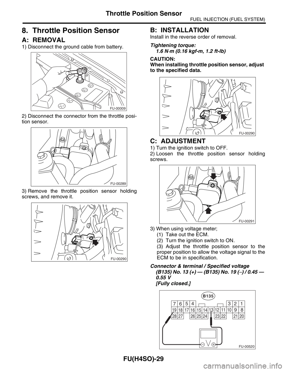
1) Disconnect the ground cable from battery.
2) Disconnect the connector from the throttle posi-
tion sensor.
3) Remove the throttle position sensor holding
screws, and remove it.
B: INSTALLATION
Install in the reverse order of removal.
Tightening torque:
1.6 N
⋅m (0.16 kgf-m, 1.2 ft-lb)
CAUTION:
When installing throttle position sensor, adjust
to the specified data.
C: ADJUSTMENT
1) Turn the ignition switch to OFF.
2) Loosen the throttle position sensor holding
screws.
3) When using voltage meter;
(1) Take out the ECM.
(2) Turn the ignition switch to ON.
(3) Adjust the throttle position sensor to the
proper position to allow the voltage signal to the
ECM to be in specification.
Connector & terminal / Specified voltage
(B135) No. 13 (+) — (B135) No. 19 (
−) / 0.45 —
0.55 V
[Fully closed.]
FU-00009
FU-00289
FU-00290
FU-00290
FU-00291
FU-00520
4
1 526
18 1516
7
891011
17
19
20121314
B135
3
2122232425262728
Page 1099 of 2870

ENGINE (DIAGNOSTIC)
EN(H4SO)
Page
1. Basic Diagnostics Procedure ......................................................................2
2. Check List for Interview ...............................................................................4
3. General Description ....................................................................................6
4. Electrical Component Location ...................................................................9
5. Engine Control Module (ECM) I/O Signal .................................................21
6. Engine Condition Data ..............................................................................24
7. Transmission Control Module (TCM) I/O Signal .......................................25
8. Data Link Connector .................................................................................26
9. OBD-II General Scan Tool ........................................................................27
10. Subaru Select Monitor...............................................................................29
11. Read Diagnostic Trouble Code (DTC) ......................................................36
12. Inspection Mode ........................................................................................37
13. Drive Cycle ................................................................................................42
14. Clear Memory Mode..................................................................................44
15. Compulsory Valve Operation Check Mode ...............................................45
16. Malfunction Indicator Light ........................................................................47
17. Diagnostics for Engine Starting Failure .....................................................57
18. List of Diagnostic Trouble Code (DTC) .....................................................72
19. Diagnostic Procedure with Diagnostic Trouble Code (DTC) .....................78
20. General Diagnostic Table........................................................................255
Page 1119 of 2870
EN(H4SO)-21
ENGINE (DIAGNOSTIC)
Engine Control Module (ECM) I/O Signal
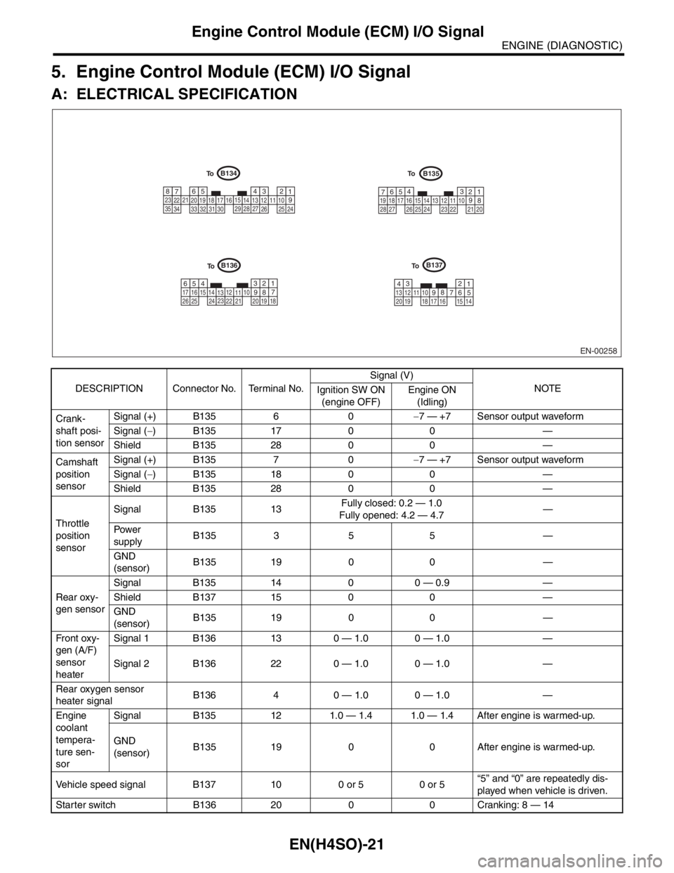
5. Engine Control Module (ECM) I/O Signal
A: ELECTRICAL SPECIFICATION
DESCRIPTION Connector No. Terminal No.Signal (V)
NOTE
Ignition SW ON
(engine OFF)Engine ON
(Idling)
Crank-
shaft posi-
tion sensorSignal (+) B135 6 0−7 — +7 Sensor output waveform
Signal (−) B135 17 0 0 —
Shield B135 28 0 0 —
Camshaft
position
sensorSignal (+) B135 7 0−7 — +7 Sensor output waveform
Signal (−) B135 18 0 0 —
Shield B135 28 0 0 —
Throttle
position
sensorSignal B135 13Fully closed: 0.2 — 1.0
Fully opened: 4.2 — 4.7—
Pow er
supplyB135 3 5 5 —
GND
(sensor)B135 19 0 0 —
Rear oxy-
gen sensorSignal B135 14 0 0 — 0.9 —
Shield B137 15 0 0 —
GND
(sensor)B135 19 0 0 —
Fr o nt ox y-
gen (A/F)
sensor
heaterSignal 1 B136 13 0 — 1.0 0 — 1.0 —
Signal 2 B136 22 0 — 1.0 0 — 1.0 —
Rear oxygen sensor
heater signalB136 4 0 — 1.0 0 — 1.0 —
Engine
coolant
tempera-
ture sen-
sorSignal B135 12 1.0 — 1.4 1.0 — 1.4 After engine is warmed-up.
GND
(sensor)B135 19 0 0 After engine is warmed-up.
Vehicle speed signal B137 10 0 or 5 0 or 5“5” and “0” are repeatedly dis-
played when vehicle is driven.
Starter switch B136 20 0 0 Cranking: 8 — 14
EN-00258
B135B134
B137B136
1234567891011121314151617181920
1 2 3 4
5
6
7 8
910 11 12 13 14 15
16
17 18
19 20 21
22 23
24
25 26 27
28
29
30 31 32
33
34 351 2 3
4
5
6
7
8 910 11
12
13 14
15 16 17
18 19
20
21 22
23 24 25
26 27
28
1 2
3
4 5 6
7
8
910
11 12
13 14 15 16
17
18 19 20 21 22 23
24
25 26
To
To
To To