lock SUBARU FORESTER 2004 Service Repair Manual
[x] Cancel search | Manufacturer: SUBARU, Model Year: 2004, Model line: FORESTER, Model: SUBARU FORESTER 2004Pages: 2870, PDF Size: 38.67 MB
Page 1 of 2870
FUJI HEAVY INDUSTRIES LTD. G8080GE7
2004 FORESTER SERVICE MANUAL QUICK REFERENCE INDEX
BODY SECTION
This service manual has been prepared
to provide SUBARU service personnel
with the necessary information and data
for the correct maintenance and repair
of SUBARU vehicles.
This manual includes the procedures
for maintenance, disassembling, reas-
sembling, inspection and adjustment of
components and diagnostics for guid-
ance of experienced mechanics.
Please peruse and utilize this manual
fully to ensure complete repair work for
satisfying our customers by keeping
their vehicle in optimum condition.
When replacement of parts during
repair work is needed, be sure to use
SUBARU genuine parts.
All information, illustration and specifi-
cations contained in this manual are
based on the latest product information
available at the time of publication
approval.HVAC SYSTEM
(HEATER, VENTILATOR AND A/C)AC
HVAC SYSTEM (AUTO A/C)
(DIAGNOSTIC)AC
AIRBAG SYSTEM AB
AIRBAG SYSTEM (DIAGNOSTIC) AB
SEAT BELT SYSTEM SB
LIGHTING SYSTEM LI
WIPER AND WASHER SYSTEM WW
ENTERTAINMENT ET
COMMUNICATION SYSTEM COM
GLASS/WINDOW/MIRROR GW
BODY STRUCTURE BS
INSTRUMENTATION/DRIVER INFO IDI
SEAT SE
SECURITY AND LOCK SL
SUNROOF/T-TOP/CONVERTIBLE TOP
(SUNROOF)SR
EXTERIOR/INTERIOR TRIM EI
EXTERIOR BODY PANEL EB
Page 55 of 2870
FUJI HEAVY INDUSTRIES LTD. G8080GE7
2004 FORESTER SERVICE MANUAL QUICK REFERENCE INDEX
BODY SECTION
This service manual has been prepared
to provide SUBARU service personnel
with the necessary information and data
for the correct maintenance and repair
of SUBARU vehicles.
This manual includes the procedures
for maintenance, disassembling, reas-
sembling, inspection and adjustment of
components and diagnostics for guid-
ance of experienced mechanics.
Please peruse and utilize this manual
fully to ensure complete repair work for
satisfying our customers by keeping
their vehicle in optimum condition.
When replacement of parts during
repair work is needed, be sure to use
SUBARU genuine parts.
All information, illustration and specifi-
cations contained in this manual are
based on the latest product information
available at the time of publication
approval.HVAC SYSTEM
(HEATER, VENTILATOR AND A/C)AC
HVAC SYSTEM (AUTO A/C)
(DIAGNOSTIC)AC
AIRBAG SYSTEM AB
AIRBAG SYSTEM (DIAGNOSTIC) AB
SEAT BELT SYSTEM SB
LIGHTING SYSTEM LI
WIPER AND WASHER SYSTEM WW
ENTERTAINMENT ET
COMMUNICATION SYSTEM COM
GLASS/WINDOW/MIRROR GW
BODY STRUCTURE BS
INSTRUMENTATION/DRIVER INFO IDI
SEAT SE
SECURITY AND LOCK SL
SUNROOF/T-TOP/CONVERTIBLE TOP
(SUNROOF)SR
EXTERIOR/INTERIOR TRIM EI
EXTERIOR BODY PANEL EB
Page 60 of 2870

AC-4
HVAC SYSTEM (AUTO A/C)(DIAGNOSTIC)
General Description
5. CONTROL SWITCHES
Start and warm-up the engine completely.
1) Inspection using switches
2) Compressor operation inspection
3) Inspection of illumination control
No. Point to check Switch operation Judgment standard
1 Fan speed control dial Turn the fan speed control dial clockwise.Fan speed changes 1st → 2nd → 3rd → 4th
as dial turn.
2AUTO switch1) Press the AUTO switch.
2) Turn the temperature control dial to the left
fully, and set maximum cool position. Outlet air temperature: COOL
Fan speed: 4th
Outlet opening: VENT
Inlet opening: RECIRC
Compressor: AUTO
3) Turn the temperature control dial to the right
slowly, and change the setting from maximum
cool position to maximum hot position gradually. Outlet air temperature: COOL → HOT
Fan speed: AUTO
Outlet opening: AUTO
Inlet opening: AUTO
Compressor: AUTO
4) Turn the temperature control dial to the right
fully, and set maximum hot position. Outlet air temperature: HOT
Fan speed: 4th
Outlet opening: HEAT
Inlet opening: FRESH
Compressor: AUTO
3 Defroster switch Press the defroster switch. Outlet air temperature: AUTO
Fan speed: AUTO
Outlet opening: DEF
Inlet opening: FRESH
Compressor: ON
4FRESH/RECIRC
switchPress the FRESH/RECIRC switch.Inlet opening switches RECIRC → FRESH or
FRESH → RECIRC each time pressing the
switch.
5 Mode control dial Press the mode control dial.Outlet opening switches VENT → BI-LEVEL
→ HEAT → DEF/HEAT each time dialing
clockwise.
No. Point to check Switch operation Judgment standard
1 Compressor1) A/C switch is turned to ON.
2) Turn the fan speed control clockwise.Compressor: ON
No. Point to check Switch operation Judgment standard
1 Illumination1) Turn the lighting switch to ON. Illumination comes on.
2) Press the OFF switch one second or more. Illumination dimming is cancelled.
Page 71 of 2870

AC-15
HVAC SYSTEM (AUTO A/C)(DIAGNOSTIC)
Diagnostics for A/C System Malfunction
Step Check Yes No
1 CHECK FUSE.
1) Remove the fuse No. 1, 2 and 17 from fuse
& relay box.
2) Check the condition of fuse.Is any fuse blown-out? Replace the fuse. Go to step 2.
2 CHECK POWER SUPPLY FOR BLOWER
MOTOR.
1) Turn the ignition switch to ON.
2) Turn the fan speed control dial clockwise.
3) Measure the voltage between blower motor
and chassis ground.
Connector & terminal
(B87) No. 1 (+) — Chassis ground (
−):Is the voltage more than 8 V (at
normal temperature)?Go to step 3.Repair the open
circuit of blower
motor power sup-
ply line harness.
3 CHECK BLOWER MOTOR RELAY.
1) Turn the ignition switch to OFF.
2) Remove the blower motor relay.
3) Connect the battery positive (+) terminal to
terminal No. 1 of blower motor relay, and nega-
tive (−) terminal to terminal No. 3.
4) Measure the resistance between terminals
No. 2 and 4.
Te r m i n a l s
No. 2 — No. 4:Is the resistance less than 1
Ω?Go to step 4.Replace the
blower motor relay.
4 CHECK BLOWER MOTOR.
1) Disconnect the connector from blower
motor.
2) Connect the battery positive (+) terminal to
terminal No. 1 of blower motor connector, and
negative (−) terminal to terminal No. 2 and No.
5.
3) Make sure the blower motor runs.Does the blower motor run? Go to step 5.Replace the
blower motor.
5 CHECK POOR CONTACT.
Check poor contact in auto A/C control module
connector.Is there poor contact in con-
nector?Repair the con-
nector.Replace the auto
A/C control mod-
ule.
Page 99 of 2870
FUJI HEAVY INDUSTRIES LTD. G8080GE7
2004 FORESTER SERVICE MANUAL QUICK REFERENCE INDEX
BODY SECTION
This service manual has been prepared
to provide SUBARU service personnel
with the necessary information and data
for the correct maintenance and repair
of SUBARU vehicles.
This manual includes the procedures
for maintenance, disassembling, reas-
sembling, inspection and adjustment of
components and diagnostics for guid-
ance of experienced mechanics.
Please peruse and utilize this manual
fully to ensure complete repair work for
satisfying our customers by keeping
their vehicle in optimum condition.
When replacement of parts during
repair work is needed, be sure to use
SUBARU genuine parts.
All information, illustration and specifi-
cations contained in this manual are
based on the latest product information
available at the time of publication
approval.HVAC SYSTEM
(HEATER, VENTILATOR AND A/C)AC
HVAC SYSTEM (AUTO A/C)
(DIAGNOSTIC)AC
AIRBAG SYSTEM AB
AIRBAG SYSTEM (DIAGNOSTIC) AB
SEAT BELT SYSTEM SB
LIGHTING SYSTEM LI
WIPER AND WASHER SYSTEM WW
ENTERTAINMENT ET
COMMUNICATION SYSTEM COM
GLASS/WINDOW/MIRROR GW
BODY STRUCTURE BS
INSTRUMENTATION/DRIVER INFO IDI
SEAT SE
SECURITY AND LOCK SL
SUNROOF/T-TOP/CONVERTIBLE TOP
(SUNROOF)SR
EXTERIOR/INTERIOR TRIM EI
EXTERIOR BODY PANEL EB
Page 109 of 2870
AB-9
AIRBAG SYSTEM
Airbag Connector
2. Airbag Connector
A: OPERATION
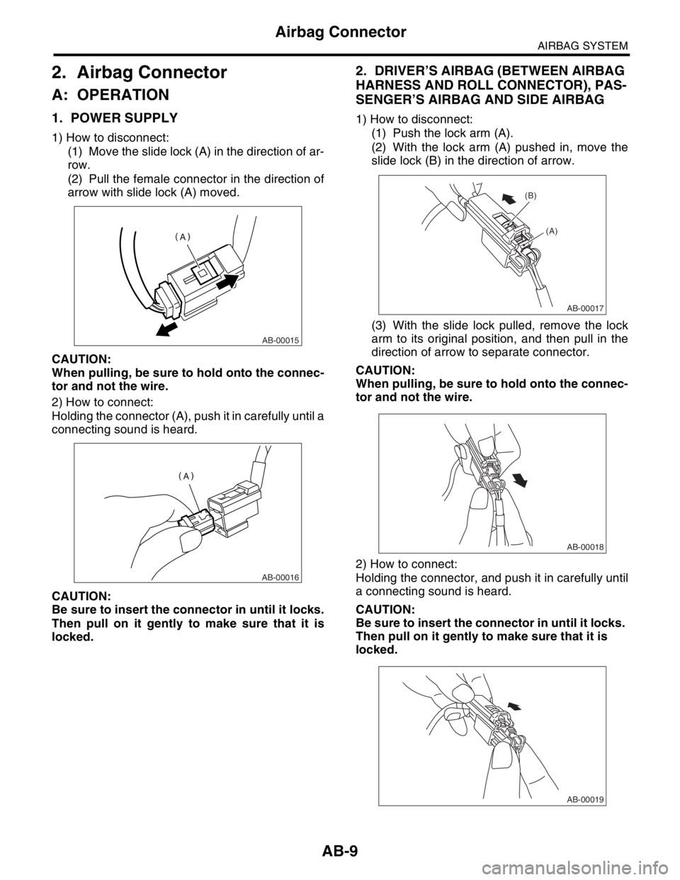
1. POWER SUPPLY
1) How to disconnect:
(1) Move the slide lock (A) in the direction of ar-
row.
(2) Pull the female connector in the direction of
arrow with slide lock (A) moved.
CAUTION:
When pulling, be sure to hold onto the connec-
tor and not the wire.
2) How to connect:
Holding the connector (A), push it in carefully until a
connecting sound is heard.
CAUTION:
Be sure to insert the connector in until it locks.
Then pull on it gently to make sure that it is
locked.
2. DRIVER’S AIRBAG (BETWEEN AIRBAG
HARNESS AND ROLL CONNECTOR), PAS-
SENGER’S AIRBAG AND SIDE AIRBAG
1) How to disconnect:
(1) Push the lock arm (A).
(2) With the lock arm (A) pushed in, move the
slide lock (B) in the direction of arrow.
(3) With the slide lock pulled, remove the lock
arm to its original position, and then pull in the
direction of arrow to separate connector.
CAUTION:
When pulling, be sure to hold onto the connec-
tor and not the wire.
2) How to connect:
Holding the connector, and push it in carefully until
a connecting sound is heard.
CAUTION:
Be sure to insert the connector in until it locks.
Then pull on it gently to make sure that it is
locked.
AB-00015
AB-00016
AB-00017
(A) (B)
AB-00018
AB-00019
Page 110 of 2870

AB-10
AIRBAG SYSTEM
Airbag Connector
3. DRIVER’S AIRBAG MODULE AND PRE-
TENSIONER
1) How to disconnect:
(1) Using a flat tip screwdriver, pry the push
lock upward to unlock.
(2) Pull the connector to disconnect from driv-
er’s side airbag module assembly or retractor
assembly.
2) How to connect:
Connect the connector in reverse order of discon-
necting. At this time, be sure to insert the connector
in until a connecting sound is heard.
CAUTION:
Be sure to insert the connector in until it
locks. Then pull it gently to make sure that it is
locked.
Be sure to insert the push lock in.
4. FRONT SUB-SENSOR AND SIDE AIR-
BAG SENSOR
1) How to disconnect:
Holding outer part (A), pull it in the direction of ar-
row.
CAUTION:
When pulling, be sure to hold onto the connec-
tor and not the wire.
2) How to connect:
Holding the connector, and push it in carefully until
a connecting sound is heard.
CAUTION:
Do not put your hand on the outer part, since
outer (A) moves back.
Be sure to insert the connector in until it
locks. Then pull it gently to make sure that it is
locked.
5. PASSENGER’S AIRBAG
1) How to disconnect:
(1) Move the slide lock (A) in the direction of ar-
row.
AB-00478
AB-00479
AB-00480
AB-00024
AB-00025
AB-00021
(A)
Page 111 of 2870
AB-11
AIRBAG SYSTEM
Airbag Connector
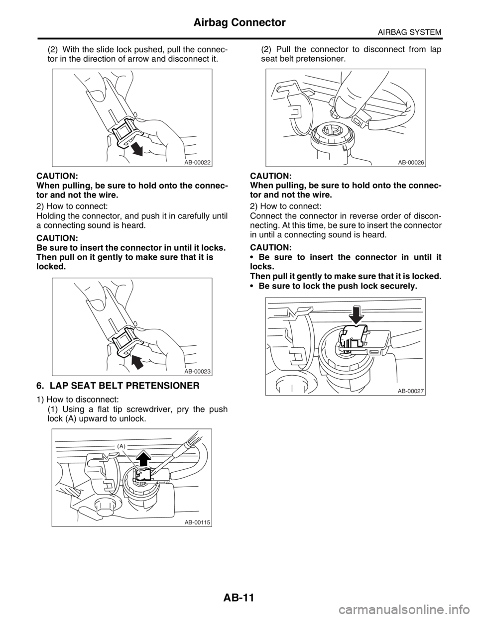
(2) With the slide lock pushed, pull the connec-
tor in the direction of arrow and disconnect it.
CAUTION:
When pulling, be sure to hold onto the connec-
tor and not the wire.
2) How to connect:
Holding the connector, and push it in carefully until
a connecting sound is heard.
CAUTION:
Be sure to insert the connector in until it locks.
Then pull on it gently to make sure that it is
locked.
6. LAP SEAT BELT PRETENSIONER
1) How to disconnect:
(1) Using a flat tip screwdriver, pry the push
lock (A) upward to unlock.(2) Pull the connector to disconnect from lap
seat belt pretensioner.
CAUTION:
When pulling, be sure to hold onto the connec-
tor and not the wire.
2) How to connect:
Connect the connector in reverse order of discon-
necting. At this time, be sure to insert the connector
in until a connecting sound is heard.
CAUTION:
Be sure to insert the connector in until it
locks.
Then pull it gently to make sure that it is locked.
Be sure to lock the push lock securely.
AB-00022
AB-00023
AB-00115
(A)
AB-00026
AB-00027
Page 120 of 2870
AB-20
AIRBAG SYSTEM
Roll Connector
9. Roll Connector
A: REMOVAL
1) Turn the ignition switch to OFF.
2) Disconnect the ground cable from battery, and
wait for at least 20 seconds before starting work.
3) Remove the driver’s airbag module.
4) Remove the steering wheel.
5) Remove the steering column cover.
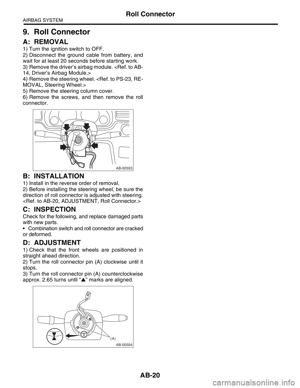
6) Remove the screws, and then remove the roll
connector.
B: INSTALLATION
1) Install in the reverse order of removal.
2) Before installing the steering wheel, be sure the
direction of roll connector is adjusted with steering.
C: INSPECTION
Check for the following, and replace damaged parts
with new parts.
Combination switch and roll connector are cracked
or deformed.
D: ADJUSTMENT
1) Check that the front wheels are positioned in
straight ahead direction.
2) Turn the roll connector pin (A) clockwise until it
stops.
3) Turn the roll connector pin (A) counterclockwise
approx. 2.65 turns until “▲” marks are aligned.
AB-00593
AB-00594
(A)
Page 131 of 2870
FUJI HEAVY INDUSTRIES LTD. G8080GE7
2004 FORESTER SERVICE MANUAL QUICK REFERENCE INDEX
BODY SECTION
This service manual has been prepared
to provide SUBARU service personnel
with the necessary information and data
for the correct maintenance and repair
of SUBARU vehicles.
This manual includes the procedures
for maintenance, disassembling, reas-
sembling, inspection and adjustment of
components and diagnostics for guid-
ance of experienced mechanics.
Please peruse and utilize this manual
fully to ensure complete repair work for
satisfying our customers by keeping
their vehicle in optimum condition.
When replacement of parts during
repair work is needed, be sure to use
SUBARU genuine parts.
All information, illustration and specifi-
cations contained in this manual are
based on the latest product information
available at the time of publication
approval.HVAC SYSTEM
(HEATER, VENTILATOR AND A/C)AC
HVAC SYSTEM (AUTO A/C)
(DIAGNOSTIC)AC
AIRBAG SYSTEM AB
AIRBAG SYSTEM (DIAGNOSTIC) AB
SEAT BELT SYSTEM SB
LIGHTING SYSTEM LI
WIPER AND WASHER SYSTEM WW
ENTERTAINMENT ET
COMMUNICATION SYSTEM COM
GLASS/WINDOW/MIRROR GW
BODY STRUCTURE BS
INSTRUMENTATION/DRIVER INFO IDI
SEAT SE
SECURITY AND LOCK SL
SUNROOF/T-TOP/CONVERTIBLE TOP
(SUNROOF)SR
EXTERIOR/INTERIOR TRIM EI
EXTERIOR BODY PANEL EB