tire SUBARU FORESTER 2004 Service Repair Manual
[x] Cancel search | Manufacturer: SUBARU, Model Year: 2004, Model line: FORESTER, Model: SUBARU FORESTER 2004Pages: 2870, PDF Size: 38.67 MB
Page 32 of 2870
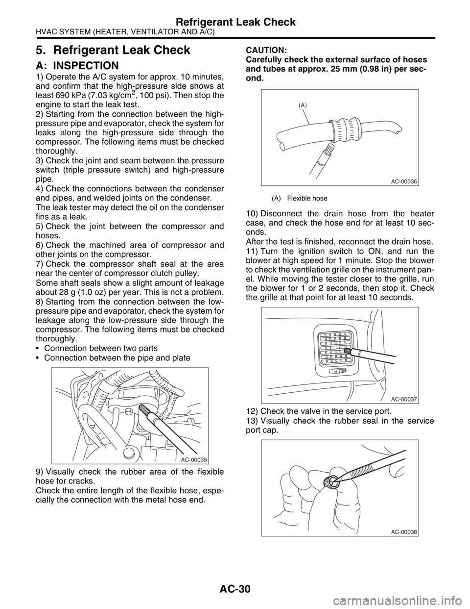
AC-30
HVAC SYSTEM (HEATER, VENTILATOR AND A/C)
Refrigerant Leak Check
5. Refrigerant Leak Check
A: INSPECTION
1) Operate the A/C system for approx. 10 minutes,
and confirm that the high-pressure side shows at
least 690 kPa (7.03 kg/cm
2, 100 psi). Then stop the
engine to start the leak test.
2) Starting from the connection between the high-
pressure pipe and evaporator, check the system for
leaks along the high-pressure side through the
compressor. The following items must be checked
thoroughly.
3) Check the joint and seam between the pressure
switch (triple pressure switch) and high-pressure
pipe.
4) Check the connections between the condenser
and pipes, and welded joints on the condenser.
The leak tester may detect the oil on the condenser
fins as a leak.
5) Check the joint between the compressor and
hoses.
6) Check the machined area of compressor and
other joints on the compressor.
7) Check the compressor shaft seal at the area
near the center of compressor clutch pulley.
Some shaft seals show a slight amount of leakage
about 28 g (1.0 oz) per year. This is not a problem.
8) Starting from the connection between the low-
pressure pipe and evaporator, check the system for
leakage along the low-pressure side through the
compressor. The following items must be checked
thoroughly.
Connection between two parts
Connection between the pipe and plate
9) Visually check the rubber area of the flexible
hose for cracks.
Check the entire length of the flexible hose, espe-
cially the connection with the metal hose end.CAUTION:
Carefully check the external surface of hoses
and tubes at approx. 25 mm (0.98 in) per sec-
ond.
10) Disconnect the drain hose from the heater
case, and check the hose end for at least 10 sec-
onds.
After the test is finished, reconnect the drain hose.
11) Turn the ignition switch to ON, and run the
blower at high speed for 1 minute. Stop the blower
to check the ventilation grille on the instrument pan-
el. While moving the tester closer to the grille, run
the blower for 1 or 2 seconds, then stop it. Check
the grille at that point for at least 10 seconds.
12) Check the valve in the service port.
13) Visually check the rubber seal in the service
port cap.
AC-00035
(A) Flexible hose
AC-00036
(A)
AC-00037
AC-00038
Page 38 of 2870
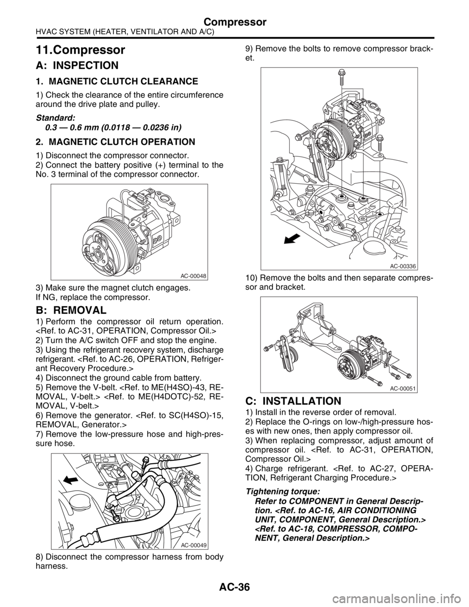
AC-36
HVAC SYSTEM (HEATER, VENTILATOR AND A/C)
Compressor
11.Compressor
A: INSPECTION
1. MAGNETIC CLUTCH CLEARANCE
1) Check the clearance of the entire circumference
around the drive plate and pulley.
Standard:
0.3 — 0.6 mm (0.0118 — 0.0236 in)
2. MAGNETIC CLUTCH OPERATION
1) Disconnect the compressor connector.
2) Connect the battery positive (+) terminal to the
No. 3 terminal of the compressor connector.
3) Make sure the magnet clutch engages.
If NG, replace the compressor.
B: REMOVAL
1) Perform the compressor oil return operation.
2) Turn the A/C switch OFF and stop the engine.
3) Using the refrigerant recovery system, discharge
refrigerant.
4) Disconnect the ground cable from battery.
5) Remove the V-belt.
6) Remove the generator.
7) Remove the low-pressure hose and high-pres-
sure hose.
8) Disconnect the compressor harness from body
harness.9) Remove the bolts to remove compressor brack-
et.
10) Remove the bolts and then separate compres-
sor and bracket.
C: INSTALLATION
1) Install in the reverse order of removal.
2) Replace the O-rings on low-/high-pressure hos-
es with new ones, then apply compressor oil.
3) When replacing compressor, adjust amount of
compressor oil.
4) Charge refrigerant.
Tightening torque:
Refer to COMPONENT in General Descrip-
tion.
AC-00048
AC-00049
AC-00336
AC-00051
Page 127 of 2870
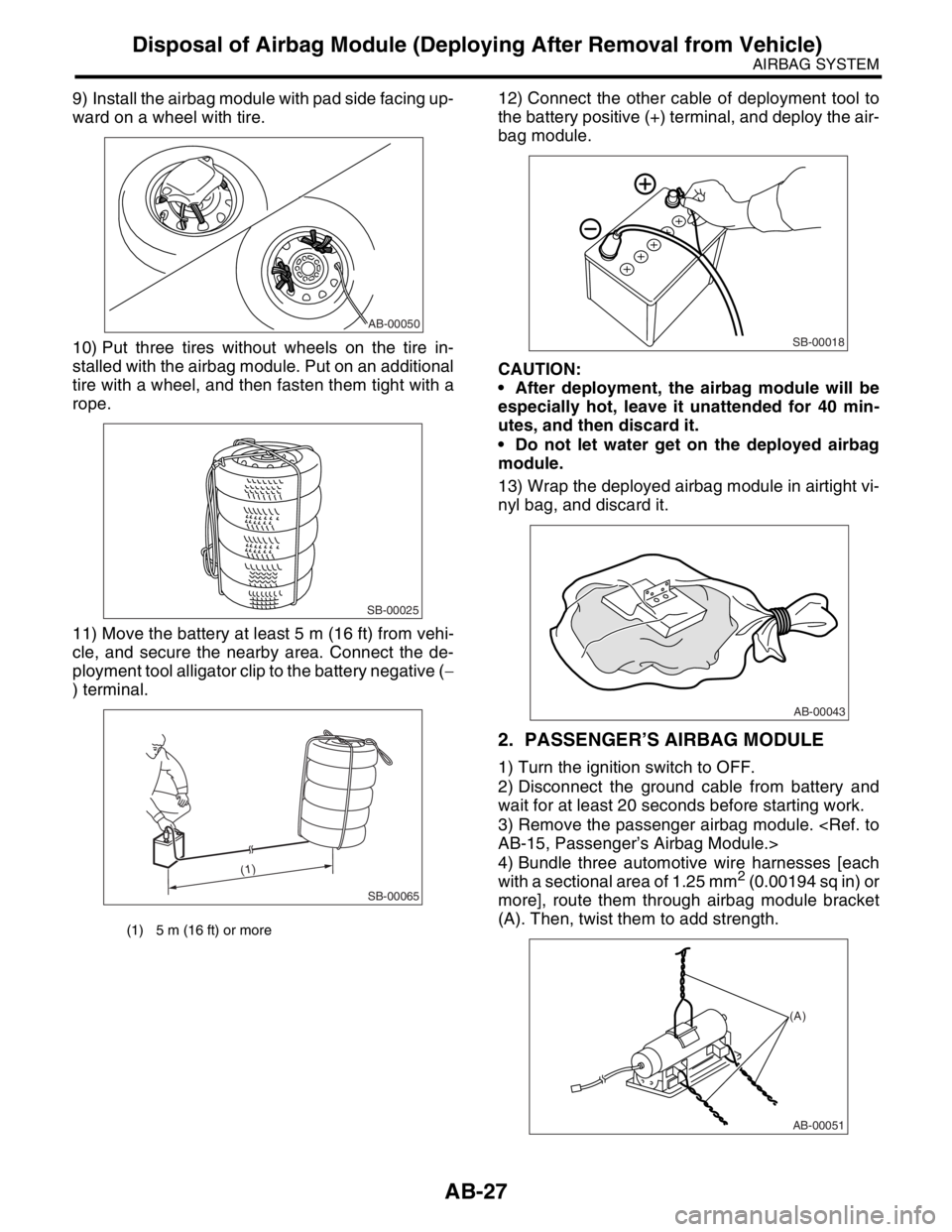
AB-27
AIRBAG SYSTEM
Disposal of Airbag Module (Deploying After Removal from Vehicle)
9) Install the airbag module with pad side facing up-
ward on a wheel with tire.
10) Put three tires without wheels on the tire in-
stalled with the airbag module. Put on an additional
tire with a wheel, and then fasten them tight with a
rope.
11) Move the battery at least 5 m (16 ft) from vehi-
cle, and secure the nearby area. Connect the de-
ployment tool alligator clip to the battery negative (−
) terminal.12) Connect the other cable of deployment tool to
the battery positive (+) terminal, and deploy the air-
bag module.
CAUTION:
After deployment, the airbag module will be
especially hot, leave it unattended for 40 min-
utes, and then discard it.
Do not let water get on the deployed airbag
module.
13) Wrap the deployed airbag module in airtight vi-
nyl bag, and discard it.
2. PASSENGER’S AIRBAG MODULE
1) Turn the ignition switch to OFF.
2) Disconnect the ground cable from battery and
wait for at least 20 seconds before starting work.
3) Remove the passenger airbag module.
4) Bundle three automotive wire harnesses [each
with a sectional area of 1.25 mm
2 (0.00194 sq in) or
more], route them through airbag module bracket
(A). Then, twist them to add strength.
(1) 5 m (16 ft) or more
AB-00050
SB-00025
SB-00065
(1)
SB-00018
AB-00043
AB-00051
(A)
Page 128 of 2870
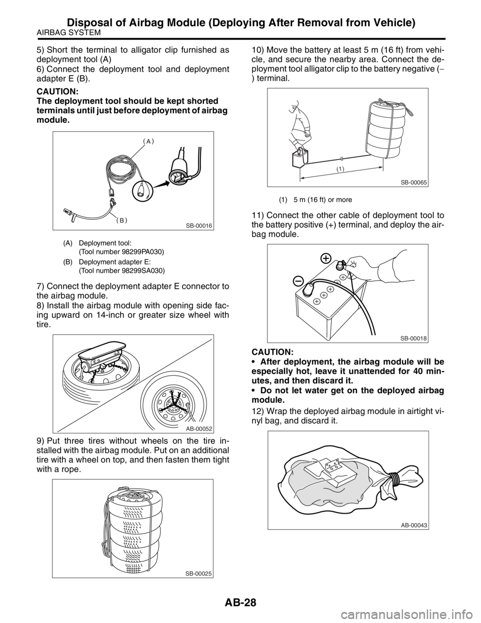
AB-28
AIRBAG SYSTEM
Disposal of Airbag Module (Deploying After Removal from Vehicle)
5) Short the terminal to alligator clip furnished as
deployment tool (A)
6) Connect the deployment tool and deployment
adapter E (B).
CAUTION:
The deployment tool should be kept shorted
terminals until just before deployment of airbag
module.
7) Connect the deployment adapter E connector to
the airbag module.
8) Install the airbag module with opening side fac-
ing upward on 14-inch or greater size wheel with
tire.
9) Put three tires without wheels on the tire in-
stalled with the airbag module. Put on an additional
tire with a wheel on top, and then fasten them tight
with a rope.10) Move the battery at least 5 m (16 ft) from vehi-
cle, and secure the nearby area. Connect the de-
ployment tool alligator clip to the battery negative (−
) terminal.
11) Connect the other cable of deployment tool to
the battery positive (+) terminal, and deploy the air-
bag module.
CAUTION:
After deployment, the airbag module will be
especially hot, leave it unattended for 40 min-
utes, and then discard it.
Do not let water get on the deployed airbag
module.
12) Wrap the deployed airbag module in airtight vi-
nyl bag, and discard it.
(A) Deployment tool:
(Tool number 98299PA030)
(B) Deployment adapter E:
(Tool number 98299SA030)
SB-00016
AB-00052
SB-00025
(1) 5 m (16 ft) or more
SB-00065
(1)
SB-00018
AB-00043
Page 129 of 2870
AB-29
AIRBAG SYSTEM
Disposal of Airbag Module (Deploying After Removal from Vehicle)
3. SIDE AIRBAG MODULE
1) Turn the ignition switch to OFF.
2) Disconnect the ground cable from battery and
wait for at least 20 seconds before starting work.
3) Remove the front seats.
4) Remove the side airbag module.
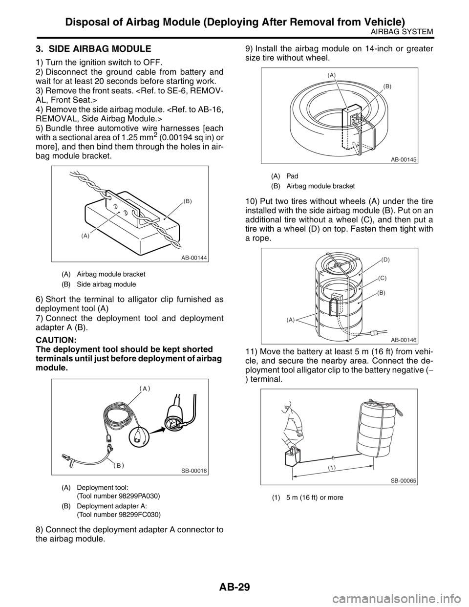
5) Bundle three automotive wire harnesses [each
with a sectional area of 1.25 mm
2 (0.00194 sq in) or
more], and then bind them through the holes in air-
bag module bracket.
6) Short the terminal to alligator clip furnished as
deployment tool (A)
7) Connect the deployment tool and deployment
adapter A (B).
CAUTION:
The deployment tool should be kept shorted
terminals until just before deployment of airbag
module.
8) Connect the deployment adapter A connector to
the airbag module.9) Install the airbag module on 14-inch or greater
size tire without wheel.
10) Put two tires without wheels (A) under the tire
installed with the side airbag module (B). Put on an
additional tire without a wheel (C), and then put a
tire with a wheel (D) on top. Fasten them tight with
a rope.
11) Move the battery at least 5 m (16 ft) from vehi-
cle, and secure the nearby area. Connect the de-
ployment tool alligator clip to the battery negative (−
) terminal.
(A) Airbag module bracket
(B) Side airbag module
(A) Deployment tool:
(Tool number 98299PA030)
(B) Deployment adapter A:
(Tool number 98299FC030)
AB-00144
(A)(B)
SB-00016
(A) Pad
(B) Airbag module bracket
(1) 5 m (16 ft) or more
AB-00145
(A)
(B)
AB-00146
(A)
(B)
(C)
(D)
SB-00065
(1)
Page 250 of 2870
SB-16
SEAT BELT SYSTEM
Disposal of Pretensioner
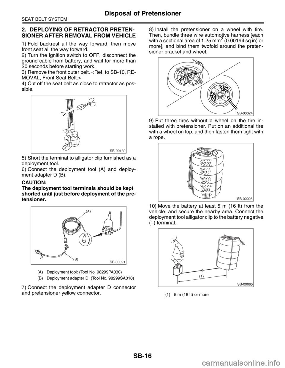
2. DEPLOYING OF RETRACTOR PRETEN-
SIONER AFTER REMOVAL FROM VEHICLE
1) Fold backrest all the way forward, then move
front seat all the way forward.
2) Turn the ignition switch to OFF, disconnect the
ground cable from battery, and wait for more than
20 seconds before starting work.
3) Remove the front outer belt.
4) Cut off the seat belt as close to retractor as pos-
sible.
5) Short the terminal to alligator clip furnished as a
deployment tool.
6) Connect the deployment tool (A) and deploy-
ment adapter D (B).
CAUTION:
The deployment tool terminals should be kept
shorted until just before deployment of the pre-
tensioner.
7) Connect the deployment adapter D connector
and pretensioner yellow connector.8) Install the pretensioner on a wheel with tire.
Then, bundle three wire automotive harness [each
with a sectional area of 1.25 mm
2 (0.00194 sq in) or
more], and bind them twofold around the preten-
sioner bracket and wheel.
9) Put three tires without a wheel on the tire in-
stalled with pretensioner. Put on an additional tire
with a wheel on top, and then fasten them tight with
a rope.
10) Move the battery at least 5 m (16 ft) from the
vehicle, and secure the nearby area. Connect the
deployment tool alligator clip to the battery negative
(−) terminal.
(A) Deployment tool: (Tool No. 98299PA030)
(B) Deployment adapter D: (Tool No. 98299SA010)
SB-00130
SB-00021
(A)
(B)
(1) 5 m (16 ft) or more
SB-00024
SB-00025
SB-00065
(1)
Page 251 of 2870
SB-17
SEAT BELT SYSTEM
Disposal of Pretensioner
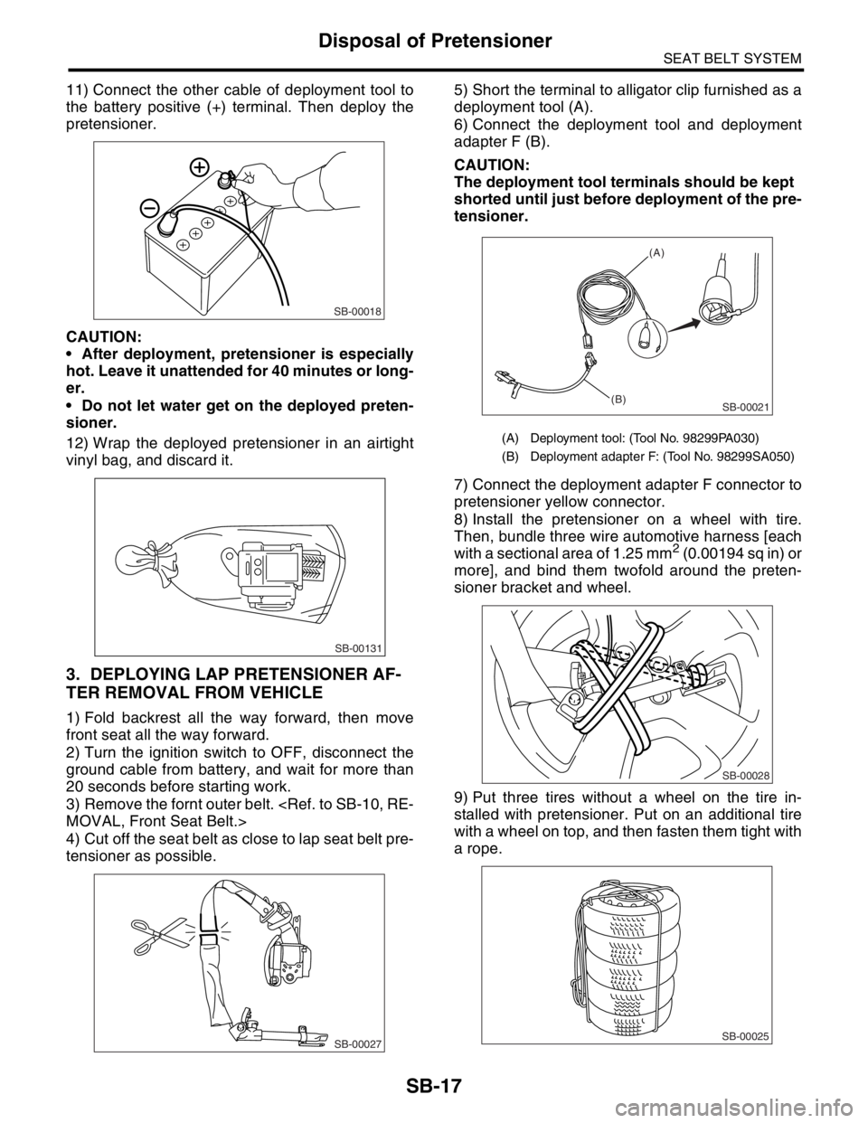
11) Connect the other cable of deployment tool to
the battery positive (+) terminal. Then deploy the
pretensioner.
CAUTION:
After deployment, pretensioner is especially
hot. Leave it unattended for 40 minutes or long-
er.
Do not let water get on the deployed preten-
sioner.
12) Wrap the deployed pretensioner in an airtight
vinyl bag, and discard it.
3. DEPLOYING LAP PRETENSIONER AF-
TER REMOVAL FROM VEHICLE
1) Fold backrest all the way forward, then move
front seat all the way forward.
2) Turn the ignition switch to OFF, disconnect the
ground cable from battery, and wait for more than
20 seconds before starting work.
3) Remove the fornt outer belt.
4) Cut off the seat belt as close to lap seat belt pre-
tensioner as possible.5) Short the terminal to alligator clip furnished as a
deployment tool (A).
6) Connect the deployment tool and deployment
adapter F (B).
CAUTION:
The deployment tool terminals should be kept
shorted until just before deployment of the pre-
tensioner.
7) Connect the deployment adapter F connector to
pretensioner yellow connector.
8) Install the pretensioner on a wheel with tire.
Then, bundle three wire automotive harness [each
with a sectional area of 1.25 mm
2 (0.00194 sq in) or
more], and bind them twofold around the preten-
sioner bracket and wheel.
9) Put three tires without a wheel on the tire in-
stalled with pretensioner. Put on an additional tire
with a wheel on top, and then fasten them tight with
a rope.
SB-00018
SB-00131
SB-00027
(A) Deployment tool: (Tool No. 98299PA030)
(B) Deployment adapter F: (Tool No. 98299SA050)
SB-00021
(A)
(B)
SB-00028
SB-00025
Page 268 of 2870
LI-14
LIGHTING SYSTEM
Headlight Assembly
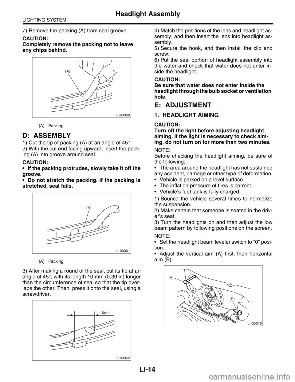
7) Remove the packing (A) from seal groove.
CAUTION:
Completely remove the packing not to leave
any chips behind.
D: ASSEMBLY
1) Cut the tip of packing (A) at an angle of 45°.
2) With the cut end facing upward, insert the pack-
ing (A) into groove around seal.
CAUTION:
If the packing protrudes, slowly take it off the
groove.
Do not stretch the packing. If the packing is
stretched, seal fails.
3) After making a round of the seal, cut its tip at an
angle of 45°, with its length 10 mm (0.39 in) longer
than the circumference of seal so that the tip over-
laps the other. Then, press it onto the seal, using a
screwdriver.4) Match the positions of the lens and headlight as-
sembly, and then insert the lens into headlight as-
sembly.
5) Secure the hook, and then install the clip and
screw.
6) Put the seal portion of headlight assembly into
the water and check that water does not enter in-
side the headlight.
CAUTION:
Be sure that water does not enter inside the
headlight through the bulb socket or ventilation
hole.
E: ADJUSTMENT
1. HEADLIGHT AIMING
CAUTION:
Turn off the light before adjusting headlight
aiming. If the light is necessary to check aim-
ing, do not turn on for more than two minutes.
NOTE:
Before checking the headlight aiming, be sure of
the following:
The area around the headlight has not sustained
any accident, damage or other type of deformation.
Vehicle is parked on a level surface.
The inflation pressure of tires is correct.
Vehicle’s fuel tank is fully charged.
1) Bounce the vehicle several times to normalize
the suspension.
2) Make certain that someone is seated in the driv-
er’s seat.
3) Turn the headlights on and then adjust the low
beam pattern by following positions on the screen.
NOTE:
Set the headlight beam leveler switch to “0” posi-
tion.
Adjust the vertical aim (A) first, then horizontal
aim (B).(A) Packing
(A) Packing
LI-00060
(A)
LI-00061
(A)
LI-00062
10mm
LI-00015
(A)
(B)
Page 502 of 2870

EI-26
EXTERIOR/INTERIOR TRIM
Front Bumper
2. REPAIR INSTRUCTIONS FOR COLORED PP BUMPER
NOTE:
All PP bumpers are provided with a grained surface, and if the surface is damaged, it cannot normally be re-
stored to its former condition. Damage limited to shallow scratches that cause only a change in the lustre of
the base material or coating, can be almost fully restored. Before repairing a damaged area, explain this point
to the customer and get an understanding about the matter. Repair methods are outlined below, based on a
classification of the extent of damage.
1) Minor damage causing only a change in the lustre of the bumper due to a light touch
Almost restorable.
2) Deep damage caused by scratching fences, etc.
A dent cannot be repaired but a whitened or swelled part can be removed.
Pro-
cess
No.Process name Job contents
1 Cleaning Clean the area to be repaired using water.
2 Sanding Grind the repairing area with #500 sand paper in a “feathering” motion.
3FinishResin section Coated section
Repeatedly apply wax to the affected area
using a soft cloth (such as flannel). Recom-
mended wax: NITTO KASEI Soft 99 TIRE WAX
BLACK, or equivalent.Perform either the same operation as for the
resin section or process No. 18 and subse-
quent operations in the “3)” section, depending
on the degree and nature of damage.
Polish the waxed area with a clean cloth after 5
to 10 minutes.
Pro-
cess
No.Process name Job contents
1 Cleaning Clean the damaged area with water.
2Removal of dam-
aged areaCut off protruding area, if any, due to collision, using a putty knife.
3 Sanding Grind the affected area with #100 to #500 sand paper.
4FinishResin section Coated section
Same as Process No. 3 in the “1)” section.Perform Process No. 12 and subsequent oper-
ations in the “3)” section.
Page 504 of 2870
EI-28
EXTERIOR/INTERIOR TRIM
Front Bumper
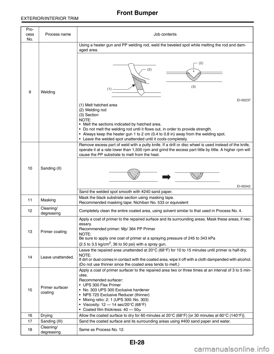
9 WeldingUsing a heater gun and PP welding rod, weld the beveled spot while melting the rod and dam-
aged area.
(1) Melt hatched area
(2) Welding rod
(3) Section
N
OTE:
Melt the sections indicated by hatched area.
Do not melt the welding rod until it flows out, in order to provide strength.
Always keep the heater gun 1 to 2 cm (0.4 to 0.8 in) away from the welding spot.
Leave the welded spot unattended until it cools completely.
10 Sanding (II)Remove excess part of weld with a putty knife. If a drill or disc wheel is used instead of the knife,
operate it at a rate lower than 1,500 rpm and grind the excess part little by little. A higher rpm will
cause the PP substrate to melt from the heat.
Sand the welded spot smooth with #240 sand paper.
11 MaskingMask the black substrate section using masking tape.
Recommended masking tape: Nichiban No. 533 or equivalent
12Cleaning/
degreasingCompletely clean the entire coated area, using solvent similar to that used in Process No. 4.
13 Primer coatingApply a coat of primer to the repaired surface and its surrounding areas. Mask these areas, if nec-
essary.
Recommended primer: Mp/ 364 PP Primer
N
OTE:
Be sure to apply one coat of primer at a spraying pressure of 245 to 343 kPa
(2.5 to 3.5 kg/cm
2, 36 to 50 psi) with a spray gun.
14 Leave unattended.Leave the repaired area unattended at 20°C (68°F) for 10 to 15 minutes until primer is half-dry.
N
OTE:
If dirt or dust comes in contact with the coated area, wipe it off with a cloth dampended with alcohol.
(Do not use thinner since the coated area tends to melt.)
15Primer surfacer
coatingApply a coat of primer surfacer to the repaired area two or three times at an interval of 3 to 5 min-
utes.
Recommended surfacer:
UPS 300 Flex Primer
No. 303 UPS 300 Exclusive hardener
NPS 725 Exclusive Reducer (thinner)
Mixing ratio: 2: 1 (UPS 300: No. 303)
Viscosity: 12 — 14 sec/20°C (68°F)
Coated film thickness: 40 — 50µ
16 Drying Allow the coated surface to dry for 60 minutes at 20°C (68°F) [or 30 minutes at 60°C (140°F)].
17 Sanding (III) Sand the coated surface and its surrounding areas using #400 sand paper and water.
18Cleaning/
degreasingSame as Process No. 12. Pro-
cess
No.Process name Job contents
EI-00237 (1)(2)(2)
(3)
EI-00042