SUBARU FORESTER 2009 SH / 3.G Owners Manual
Manufacturer: SUBARU, Model Year: 2009, Model line: FORESTER, Model: SUBARU FORESTER 2009 SH / 3.GPages: 384, PDF Size: 13.91 MB
Page 351 of 384

12-4Specifications
&Capacities
Fuel tank 16.9 US gal (64 liters, 14.1 Imp gal)
Engine oil 4.2 US qt (4.0 liters, 3.5 Imp qt)
Transmission oil (MT) 3.7 US qt (3.5 liters, 3.1 Imp qt)
Transmission fluid (AT) 9.8 US qt (9.3 liters, 8.2 Imp qt)
Front differential gear oil (AT) 1.3 US qt (1.2 liters, 1.1 Imp qt)
Rear differential gear oil 0.8 US qt (0.8 liters, 0.7 Imp qt)
Power steering fluid 0.7 US qt (0.7 liter, 0.6 Imp qt)
Engine coolant Non-turbo engine MT 7.2 US qt (6.8 liters, 6.0 Imp qt)
AT 7.1 US qt (6.7 liters, 5.9 Imp qt)
Turbo engine 8.5 US qt (8.0 liters, 7.0 Imp qt)
AT: Automatic transmission
MT: Manual transmission
Page 352 of 384

&Tires
Tire size P215/65R16 96H P225/55R17 95H
Wheel size 16 66
1/2J1 66 61/2JJ 17 67JJ
Pressure Front 30 psi (210 kPa, 2.1 kgf/cm2) 32 psi (220 kPa, 2.2 kgf/cm2)
Rear 29 psi (200 kPa, 2.0 kgf/cm2) 30 psi (210 kPa, 2.1 kgf/cm2)
Temporary
spare tire Size
T155/70 D17
Pressure 60 psi (420 kPa, 4.2 kgf/cm
2)
NOTE
For the Latin American models, there is a conventional tire installed under the floor of the cargo area. & Wheel alignment
Item 2.5-liter non-turbo 2.5-liter turbo
2.5X 2.5X Premium 2.5X Touring 2.5X LLBean 2.5X Limited 2.5XT 2.5XT Limited
Drive system AWD
Toe Front 0 in (0 mm)
Rear 0 in (0 mm)
Camber Front 0800 ’
Rear 0
800 ’ Specifications
12-5
Page 353 of 384
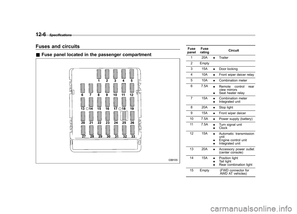
12-6Specifications
Fuses and circuits &Fuse panel located in the passenger compartmentFuse
panel Fuse
rating Circuit
1 20A .Trailer
2 Empty
3 15A .Door locking
4 10A .Front wiper deicer relay
5 10A .Combination meter
6 7.5A .Remote control rear
view mirrors
. Seat heater relay
7 15A .Combination meter
. Integrated unit
8 20A .Stop light
9 15A .Front wiper deicer
10 7.5A .Power supply (battery)
11 7.5A .Turn signal unit
. Clock
12 15A .Automatic transmission
unit
. Engine control unit
. Integrated unit
13 20A .Accessory power outlet
(center console)
14 15A .Position light
. Tail light
. Rear combination light
15 Empty (FWD connector for AWD AT vehicles)
Page 354 of 384

Fuse
panel Fuse
rating Circuit
16 10A .Illumination
17 15A .Seat heaters
18 10A .Back-up light
19 Empty
20 10A .Accessory power outlet
(instrument panel)
21 7.5A .Starter relay
22 15A .Air conditioner
. Rear window defogger
relay coil
23 15A .Rear wiper
. Rear window washer
24 15A .Audio unit
. Clock
25 15A .SRS airbag system
26 7.5A .Power window relay
. Radiator main fan relay
. Tail and illumination re-
lay
27 15A .Blower fan
28 15A .Blower fan
29 15A .Fog light
30 30A .Front wiper
31 7.5A .Auto air conditioner unit
. Integrated unit Fuse
panel Fuse
rating Circuit
32 Empty
33 7.5A .ABS/Vehicle dynamics
control unit Specifications
12-7
– CONTINUED –
Page 355 of 384
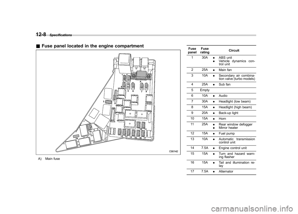
12-8Specifications
&Fuse panel located in the engine compartment
A) Main fuse Fuse
panel Fuse
rating Circuit
1 30A .ABS unit
. Vehicle dynamics con-
trol unit
2 25A .Main fan
3 10A .Secondary air combina-
tion valve (turbo models)
4 25A .Sub fan
5 Empty
6 10A .Audio
7 30A .Headlight (low beam)
8 15A .Headlight (high beam)
9 20A .Back-up light
10 15A .Horn
11 25A .Rear window defogger
. Mirror heater
12 15A .Fuel pump
13 10A .Automatic transmission
control unit
14 7.5A .Engine control unit
15 15A .Turn and hazard warn-
ing flasher
16 15A .Tail and illumination re-
lay
17 7.5A .Alternator
Page 356 of 384

Fuse
panel Fuse
rating Circuit
18 15A .Headlight (right hand)
19 15A .Headlight (left hand) Bulb chart
Description Wattage Bulb No.
Headlight Low beam headlight 12V-55W H11
High beam headlight 12V-60W 9005 (HB3)
Front fog light 12V-51W 9006 (HB4)
Front turn signal light 12V-21W WY21W
Position light 12V-5W 168 (W5W)
Front side marker light 12V-5W 168 (W5W)
Rear combination light
Brake/tail light/Rear side marker light 12V-21W/5W 7443
Rear turn signal light 12V-21W (WY21W)
Back-up light 12V-21W 7440
License plate light 12V-5W 168 (W5W)
Cargo area light 12V-13W –
Dome light 12V-8W –
Map light 12V-8W –
Door step light 12V-5W –Specifications
12-9
Page 357 of 384
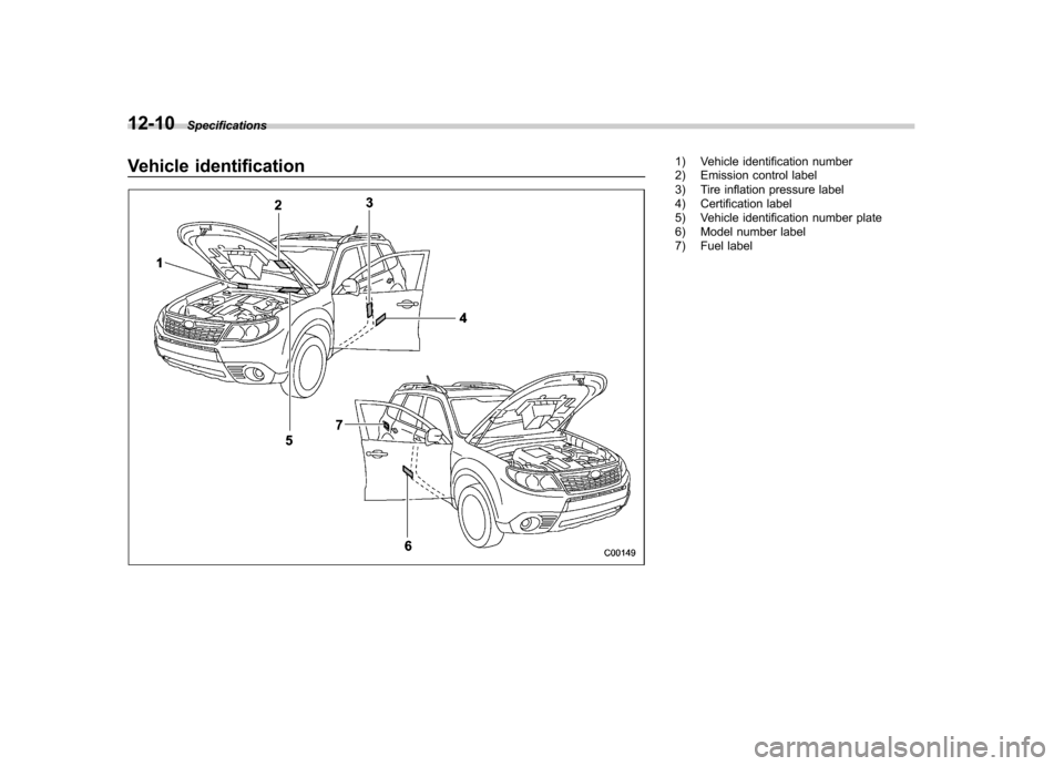
12-10Specifications
Vehicle identification1) Vehicle identification number
2) Emission control label
3) Tire inflation pressure label
4) Certification label
5) Vehicle identification number plate
6) Model number label
7) Fuel label
Page 358 of 384
For U.S.A............................................................ 13-2
Tire information .................................................. 13-2
Tire labeling ....................................................... 13-2
Recommended tire inflation pressure .................. 13-5
Glossary of tire terminology ............................... 13-6
Tire care –maintenance and safety practices ...... 13-7
Vehicle load limit –how to determine .................. 13-8
Determining compatibility of tire and vehicle load capacities ...................................................... 13-11 Adverse safety consequences of overloading on
handling and stopping and on tires ................ 13-11
Steps for Determining Correct Load Limit ......... 13-11
Uniform tire quality grading standards .......... 13-12
Treadwear ....................................................... 13-12
Traction AA, A, B, C ......................................... 13-12
Temperature A, B, C ......................................... 13-13
Reporting safety defects (U.S.A.) ................... 13-13
Consumer information and Reporting safety defects
13
Page 359 of 384
13-2Consumer information and Reporting safety defects
For U.S.A.
The following information has been
compiled according to Code of
Federal Regulations “Title 49, Part
575 ”. Tire information &
Tire labeling
Many markings (e.g. Tire size, Tire
Identification Number or TIN) are
placed on the sidewall of a tire by
tire manufacturers. These markings
can provide you with useful infor-
mation on the tire. ! Tire size
Your vehicle comes equipped with
P-Metric tire size. It is important to
understand the sizing system in
selecting the proper tire for your
vehicles. Here is a brief review of
the tire sizing system with a break-
down of its individual elements. ! P Metric
With the P-Metric system, Section
Width is measured in millimeters.
To convert millimeters into inches,
divide by 25.4. The Aspect Ratio
(Section Height divided by Section
Width) helps provide more dimen-
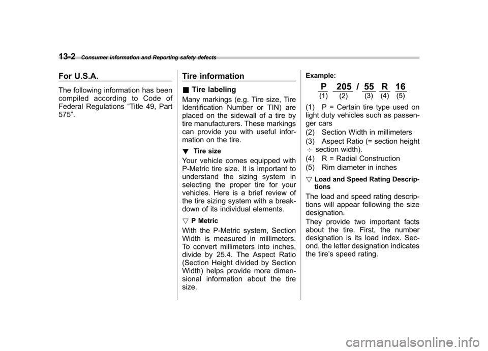
sional information about the tiresize. Example:
(1) P = Certain tire type used on
light duty vehicles such as passen-
ger cars
(2) Section Width in millimeters
(3) Aspect Ratio (= section height 7
section width).
(4) R = Radial Construction
(5) Rim diameter in inches ! Load and Speed Rating Descrip- tions
The load and speed rating descrip-
tions will appear following the size designation.
They provide two important facts
about the tire. First, the number
designation is its load index. Sec-
ond, the letter designation indicates
the tire ’s speed rating.
Page 360 of 384
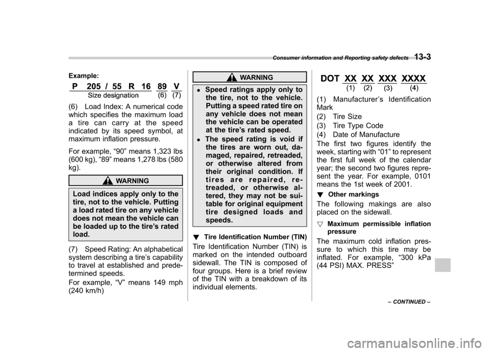
Example:
(6) Load Index: A numerical code
which specifies the maximum load
a tire can carry at the speed
indicated by its speed symbol, at
maximum inflation pressure.
For example,“90 ”means 1,323 lbs
(600 kg), “89 ”means 1,278 lbs (580
kg).
WARNING
Load indices apply only to the
tire, not to the vehicle. Putting
a load rated tire on any vehicle
does not mean the vehicle can
be loaded up to the tire ’s rated
load.
(7) Speed Rating: An alphabetical
system describing a tire ’s capability
to travel at established and prede-
termined speeds.
For example, “V ” means 149 mph
(240 km/h)
WARNING
. Speed ratings apply only to
the tire, not to the vehicle.
Putting a speed rated tire on
any vehicle does not mean
the vehicle can be operated
at the tire ’s rated speed.
. The speed rating is void if
the tires are worn out, da-
maged, repaired, retreaded,
or otherwise altered from
their original condition. If
tires are repaired, re-
treaded, or otherwise al-
tered, they may not be sui-
table for original equipment
tire designed loads andspeeds.
! Tire Identification Number (TIN)
Tire Identification Number (TIN) is
marked on the intended outboard
sidewall. The TIN is composed of
four groups. Here is a brief review
of the TIN with a breakdown of its
individual elements.
(1) Manufacturer ’s Identification
Mark
(2) Tire Size
(3) Tire Type Code
(4) Date of Manufacture
The first two figures identify the
week, starting with “01 ”to represent
the first full week of the calendar
year; the second two figures repre-
sent the year. For example, 0101
means the 1st week of 2001.
! Other markings
The following makings are also
placed on the sidewall. ! Maximum permissible inflation
pressure
The maximum cold inflation pres-
sure to which this tire may be
inflated. For example, “300 kPa
(44 PSI) MAX. PRESS ”
Consumer information and Reporting safety defects
13-3
– CONTINUED –