immobilizer SUBARU FORESTER 2009 SH / 3.G Owners Manual
[x] Cancel search | Manufacturer: SUBARU, Model Year: 2009, Model line: FORESTER, Model: SUBARU FORESTER 2009 SH / 3.GPages: 384, PDF Size: 13.91 MB
Page 88 of 384

Keys..................................................................... 2-2
Key number plate ................................................ 2-2
Immobilizer .......................................................... 2-2
Security ID plate .................................................. 2-3
Security indicator light ........................................ 2-3
Key replacement ................................................. 2-4
Door locks ........................................................... 2-4
Locking and unlocking from the outside .. ............ 2-4
Locking and unlocking from the inside ................ 2-5
Battery drainage prevention function ................... 2-5
Power door locking switches ............................. 2-6
Key lock-in prevention function ........................... 2-6
Remote keyless entry system ............................ 2-7
Locking the doors ............................................... 2-8
Unlocking the doors ............................................ 2-8
Unlocking the rear gate ....................................... 2-9
Illuminated entry ................................................. 2-9
Vehicle finder function ......................................... 2-9
Sounding a panic alarm ....................................... 2-9
Selecting audible signal operation ....................... 2-9
Replacing the battery ......................................... 2-10 Replacing lost transmitters
................................ 2-10
Alarm system ..................................................... 2-14
System operation ............................................... 2-14
Activating and deactivating the alarm system ..... 2-14
If you have accidentally triggered the alarm system ............................................................ 2-14
Arming the system ............................................ 2-15
Disarming the system ........................................ 2-16
Valet mode ........................................................ 2-16
Passive arming .................................................. 2-16
Tripped sensor identification .............................. 2-17
Shock sensors (dealer option).. .......................... 2-18
Child safety locks .............................................. 2-18
Windows ............................................................. 2-19
Power windows ................................................. 2-19
Rear gate ............................................................ 2-21
Moonroof (if equipped) ...................................... 2-22
To open the moonroof ....................................... 2-23
To close the moonroof ....................................... 2-23
Anti-entrapment function .................................... 2-23
Sun shade ......................................................... 2-23 Keys and doors
2
Page 89 of 384
2-2Keys and doors
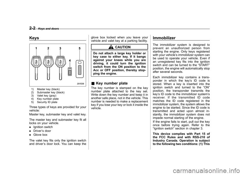
Keys
1) Master key (black)
2) Submaster key (black)
3) Valet key (gray)
4) Key number plate
5) Security ID plate
Three types of keys are provided for your vehicle:
Master key, submaster key and valet key.
The master key and submaster key fit all
locks on your vehicle. . Ignition switch
. Driver ’s door
. Glove box
The valet key fits only the ignition switch
and driver ’s door lock. You can keep the glove box locked when you leave your
vehicle and valet key at a parking facility.
CAUTION
Do not attach a large key holder or
key case to either key. If it bangs
against your knees while you are
driving, it could turn the ignition
switch from the ON position to the
Acc or OFF position, thereby stop-
ping the engine.
& Key number plate
The key number is stamped on the key
number plate attached to the key set.
Write down the key number and keep it in
another safe place, not in the vehicle. This
number is needed to make a replacement
key if you lose your key or lock it inside thevehicle. Immobilizer
The immobilizer system is designed to
prevent an unauthorized person from
starting the engine. Only keys registered
with your vehicle
’s immobilizer system can
be used to operate your vehicle. Even if
an unregistered key fits into the ignition
switch and can be turned to the “START ”
position, the engine will automatically stop
after several seconds.
Each immobilizer key contains a trans-
ponder in which the key ’s ID code is
stored. When a key is inserted into the
ignition switch and turned to the “ON ”
position, the transponder transmits thekey ’s ID code to the immobilizer system ’s
receiver. If the transmitted ID code
matches the ID code registered in the
immobilizer system, the system allows the
engine to be started. Since the ID code is
transmitted and acted upon almost in-
stantly, the immobilizer system does not
impede normal starting of the engine.
If the engine fails to start, pull out the key
once before trying again. Refer to the“ Ignition switch ”section in chapter 3.
This device complies with Part 15 of
the FCC Rules and with RSS-210 of
Industry Canada. Operation is subject
to the following two conditions: (1) This
Page 90 of 384
device may not cause harmful inter-
ference, and (2) this device must
accept any interference received, in-
cluding interference that may cause
undesired operation.
Changes or modifications not ex-
pressly approved by the party respon-
sible for compliance could void theuser’s authority to operate the equip-
ment. NOTE
To protect your vehicle from theft,
please pay close attention to the fol-
lowing security precautions: . Never leave your vehicle unattended
with its keys inside. . Before leaving your vehicle, close all
windows and lock the doors and reargate.. Do not leave spare keys or any
record of your key number in thevehicle.
CAUTION
. Do not place the key under direct
sunlight or anywhere it may
become hot. .
Do not get the key wet. If the key
gets wet, wipe it dry with a cloth
immediately.
& Security ID plate
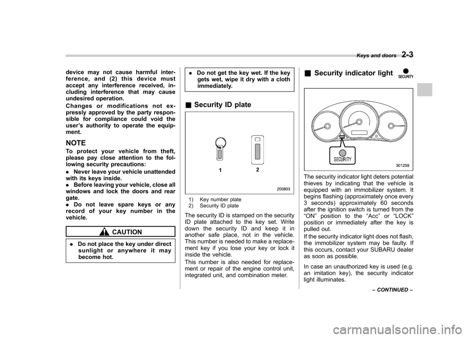
1) Key number plate
2) Security ID plate
The security ID is stamped on the security
ID plate attached to the key set. Write
down the security ID and keep it in
another safe place, not in the vehicle.
This number is needed to make a replace-
ment key if you lose your key or lock it
inside the vehicle.
This number is also needed for replace-
ment or repair of the engine control unit,
integrated unit, and combination meter. &
Security indicator light
The security indicator light deters potential
thieves by indicating that the vehicle is
equipped with an immobilizer system. It
begins flashing (approximately once every
3 seconds) approximately 60 seconds
after the ignition switch is turned from the“ON ”position to the “Acc ”or “LOCK ”
position or immediately after the key is
pulled out.
If the security indicator light does not flash,
the immobilizer system may be faulty. If
this occurs, contact your SUBARU dealer
as soon as possible.
In case an unauthorized key is used (e.g.
an imitation key), the security indicator
light illuminates. Keys and doors
2-3
– CONTINUED –
Page 91 of 384

2-4Keys and doors
NOTE
Even if the security indicator light
flashes irregularly or its fuse blows
(the light does not flash if its fuse is
blown), the immobilizer system will
function normally. &Key replacement
Your key number plate and security ID
plate will be required if you ever need a
replacement key made. Any new key must
be registered for use with your vehicle ’s
immobilizer system before it can be used.
Up to four keys can be registered for use
with one vehicle.
For security, all the keys registered with
your vehicle ’s immobilizer system will
have their ID codes erased and re-
registered when a new key is made.
Therefore, all of your vehicle ’s keys must
be presented when a new key is regis-
tered. Any key that is not re-registered
when a new key is made cannot be used
after the other keys are re-registered. For
information on replacement keys and on
the registration of keys with your immo-
bilizer system, contact your SUBARU
dealer. NOTE
A vehicle that is equipped with the
remote engine start system as a dealer
option can register up to three keys for
use with one vehicle.
Door locks &
Locking and unlocking from
the outside
To lock the driver ’s door from the outside
with the key, turn the key toward the rear.
To unlock the door, turn the key toward thefront.
Pull the outside door handle to open an
unlocked door.
Page 116 of 384
contains an immobilizer transponder. .The key is near or touching another
transmitter. & Key reminder chime
The reminder chime sounds when the driver ’s door opens and the key is in the
“ LOCK ”or “Acc ”position. The chime stops
when the ignition switch is turned to the“ ON ”position or the key is removed from
the ignition switch.
& Ignition switch light
For easy access to the ignition switch in
the dark, the ignition switch light illumi-
nates when driver ’s door is opened. The
light remains on for 20 seconds and turns
off after driver ’s door is closed. The light
turns off immediately if the key is turned tothe “ON ”position. Hazard warning flasher
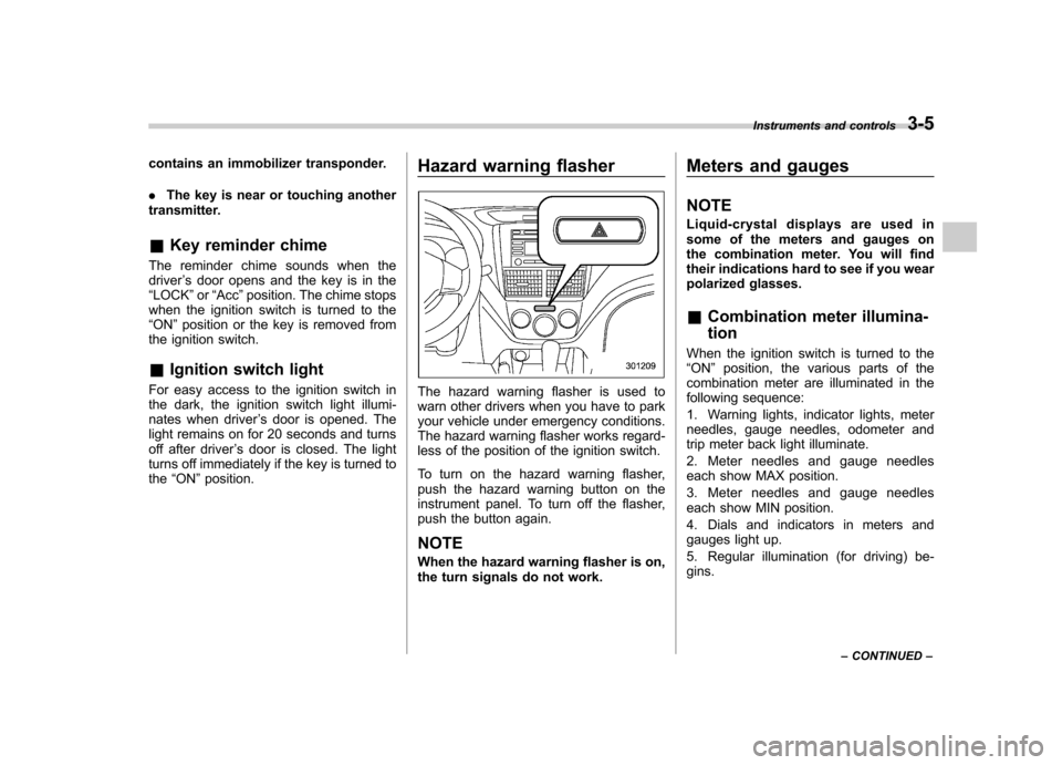
The hazard warning flasher is used to
warn other drivers when you have to park
your vehicle under emergency conditions.
The hazard warning flasher works regard-
less of the position of the ignition switch.
To turn on the hazard warning flasher,
push the hazard warning button on the
instrument panel. To turn off the flasher,
push the button again. NOTE
When the hazard warning flasher is on,
the turn signals do not work. Meters and gauges NOTE
Liquid-crystal displays are used in
some of the meters and gauges on
the combination meter. You will find
their indications hard to see if you wear
polarized glasses. &
Combination meter illumina- tion
When the ignition switch is turned to the “ ON ”position, the various parts of the
combination meter are illuminated in the
following sequence:
1. Warning lights, indicator lights, meter
needles, gauge needles, odometer and
trip meter back light illuminate.
2. Meter needles and gauge needles
each show MAX position.
3. Meter needles and gauge needles
each show MIN position.
4. Dials and indicators in meters and
gauges light up.
5. Regular illumination (for driving) be- gins. Instruments and controls
3-5
– CONTINUED –
Page 130 of 384
ABS systems are inoperative in this case,
the ordinary functions of the brake system
are still available. You will be safe while
driving with this condition, but have your
vehicle checked at a SUBARU dealer as
soon as possible. NOTE
If the warning light behavior is as
described below, the Vehicle Dynamics
Control system may be considerednormal. .The warning light illuminates right
after the engine is started but turns off
immediately, remaining off.. The warning light illuminates after
engine startup and turns off while the
vehicle is subsequently being driven.. The warning light illuminates during
driving, but it turns off immediately and
remains off. ! Vehicle Dynamics Control OFF in-
dicator light
. It illuminates when the Vehicle Dy-
namics Control OFF switch is pressed. . It also illuminates when the Vehicle
Dynamics Control system is deactivated. NOTE . The light may stay on for a while
after the engine has been started, especially in cold weather. This does
not indicate the existence of a problem.
The light should turn off as soon as the
engine has warmed up..
The indicator light illuminates when
the engine has developed a problem
and the CHECK ENGINE warning light/
malfunction indicator lamp is on.
The Vehicle Dynamics Control system is
probably faulty under the following condi-
tion. Have your vehicle checked at a
SUBARU dealer as soon as possible. . The light does not turn off even after
the lapse of several minutes (the engine
has warmed up) after the engine hasstarted. &
Security indicator light
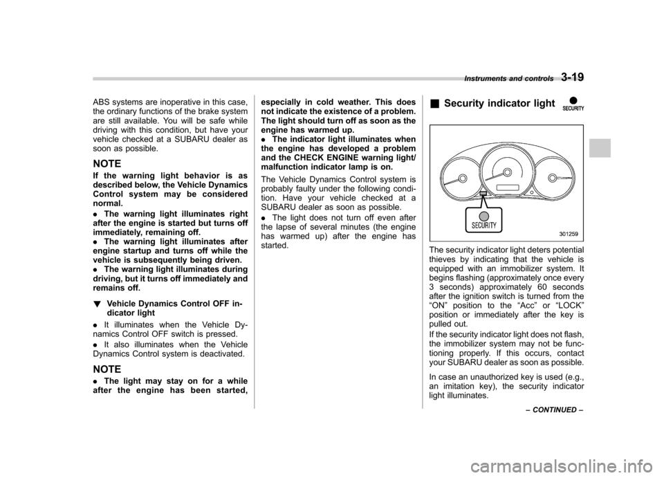
The security indicator light deters potential
thieves by indicating that the vehicle is
equipped with an immobilizer system. It
begins flashing (approximately once every
3 seconds) approximately 60 seconds
after the ignition switch is turned from the“ON ”position to the “Acc ”or “LOCK ”
position or immediately after the key is
pulled out.
If the security indicator light does not flash,
the immobilizer system may not be func-
tioning properly. If this occurs, contact
your SUBARU dealer as soon as possible.
In case an unauthorized key is used (e.g.,
an imitation key), the security indicator
light illuminates. Instruments and controls
3-19
– CONTINUED –
Page 131 of 384
3-20Instruments and controls
NOTE
Even if the security indicator light
flashes irregularly or its fuse blows
(the light does not flash if its fuse is
blown), the immobilizer system will
function normally. & SPORT mode indicator
light (AT vehicles)
This light illuminates when the ignition
switch is turned to the “ON ”position and
turns off after the engine has started.
When the selector lever is moved to the
manual gate, the SPORT mode is se-
lected and the indicator light illuminates.
Refer to the “SPORT mode ”section in
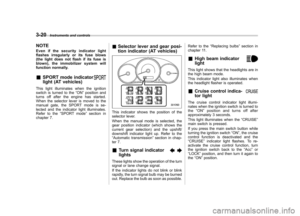
chapter 7. &
Selector lever and gear posi-
tion indicator (AT vehicles)
This indicator shows the position of the
selector lever.
When the manual mode is selected, the
gear position indicator (which shows the
current gear selection) and the upshift/
downshift indicator light up. Refer to the“Automatic transmission ”section in chap-
ter 7. & Turn signal indicator lights
These lights show the operation of the turn
signal or lane change signal.
If the indicator lights do not blink or blink
rapidly, the turn signal bulb may be burned
out. Replace the bulb as soon as possible. Refer to the
“Replacing bulbs ”section in
chapter 11.
& High beam indicator light
This light shows that the headlights are in
the high beam mode.
This indicator light also illuminates when
the headlight flasher is operated. &Cruise control indica-
tor light
The cruise control indicator light illumi-
nates when the ignition switch is turned tothe “ON ”position and turns off after
approximately 3 seconds.
This light illuminates when the “CRUISE ”
main switch is pressed.
If you press the main switch button while
turning the ignition switch “ON ”, the cruise
control function is deactivated and the“ CRUISE ”indicator light flashes. To re-
activate the cruise control function, turn
the ignition switch back to the “Acc ”or
“ LOCK ”position, and then turn it again to
the “ON ”position.
Page 376 of 384

Fuel........................................................................... 7-2
Economy hints ......................................................... 8-2
Filler lid and cap ...................................................... 7-3
Gauge .................................................................... 3-8
Requirements .......................................................... 7-2
Fuses ...................................................................... 11-44
Fuses and circuits ...................................................... 12-6
G
GAWR (Gross Axle Weight Rating) .............................. 8-13
Glove box ................................................................... 6-5
GVWR (Gross Vehicle Weight Rating) .......................... 8-13
H
Hazard warning flasher ........................................... 3-5, 9-2
Head restraint adjustment
Front seat ............................................................... 1-5
Rearseat ................................................................. 1-7
Headlight
Beam lever ........................................................... 3-26
Flasher ................................................................. 3-25
Indicator light ......................................................... 3-21
Headlights ........................................................ 3-24, 11-47
Heater operation (manual climate control system) ............ 4-5
High beam indicator light ............................................ 3-20
High/low beam change (dimmer) .................................. 3-25
Hill start assist (MT vehicles) .............................. 7-33, 11-29
Hill start assist warning light ................................ 3-17, 7-34
Horn ......................................................................... 3-38
Hose and connections ............................................... 11-12 I
Ignition switch
............................................................. 3-3
Light ...................................................................... 3-5
Illuminated entry .......................................................... 2-9
Illumination brightness control ...................................... 3-26
Immobilizer ................................................................. 2-2
Indicator light (security indicator light) ................. 2-3, 3-19
Indicator light Coolant temperature low .......................................... 3-13
Cruise control ................................................ 3-20, 7-37
Cruise control set ........................................... 3-21, 7-38
Front fog light ......................................................... 3-21
Headlight ............................................................... 3-21
High beam ............................................................. 3-20
Immobilizer ............................................................. 2-3
Security .......................................................... 2-3, 3-19
Selector lever/Gear position ..................................... 3-20
SPORT mode ........................................................ 3-20
Traction control system OFF .................................... 3-18
Turn signal ............................................................ 3-20
Vehicle Dynamics Control OFF ......................... 3-19, 7-28
Vehicle Dynamics Control operation .................. 3-18, 7-27
Information display ...................................................... 3-22
Inside mirror .............................................................. 3-33
Interior lights ............................................................... 6-2
J
Jack handle ............................................................... 9-17
Jump starting .............................................................. 9-9 Index
14-5