Control unit SUBARU FORESTER 2017 SJ / 4.G Owners Manual
[x] Cancel search | Manufacturer: SUBARU, Model Year: 2017, Model line: FORESTER, Model: SUBARU FORESTER 2017 SJ / 4.GPages: 634, PDF Size: 11.77 MB
Page 6 of 634
Warranties
&Warranties for U.S.A.
All SUBARU vehicles distributed by
Subaru of America, Inc. and sold at retail
by an authorized SUBARU dealer in the
United States come with the following
warranties:
. SUBARU Limited Warranty
. Emission Control Systems Warranty
. Emissions Performance Warranty
All warranty information, including details
of coverage and exclusions, is in the
“ Warranty and Maintenance Booklet ”.
Read these warranties carefully.
& Warranties for Canada
All SUBARU vehicles distributed by
Subaru Canada, Inc. and sold at retail by
an authorized SUBARU dealer in Canada
come with the following warranties:
. SUBARU Limited Warranty
. Anti-Corrosion Warranty
. Emission Control Warranty
All warranty information, including details
of coverage and exclusions, is in the
“ Warranty and Service Booklet ”. Read
these warranties carefully.
& Warranties except for U.S.A.
and Canada
All warranty information, including details
of coverage and exclusions, is in the
“Warranty and Maintenance Booklet ”.
Read these warranties carefully.
How to use this Owner ’s
Manual
& Using your Owner ’s Manual
Before you operate your vehicle, carefully
read this manual. To protect yourself and
extend the service life of your vehicle,
follow the instructions in this manual.
Failure to observe these instructions may
result in serious injury and damage to your
vehicle.
This manual is composed of fourteen
chapters. Each chapter begins with a brief
table of contents, so you can usually tell at
a glance if that chapter contains the
information you want.
Chapter 1: Seat, seatbelt and SRS
airbags
This chapter informs you how to use the
seat and seatbelt and contains precau-
tions for the SRS airbags.
Chapter 2: Keys and doors
This chapter informs you how to operate
the keys, locks and windows.
Chapter 3: Instruments and controls
This chapter informs you about the opera-
tion of instrument panel indicators and
how to use the instruments and other
switches.
– CONTINUED –
1
Page 93 of 634
Seat, seatbelt and SRS airbags/*SRS airbag (Supplemental Restraint System airbag)
between the occupant and the side
window and supplements the seatbelt by
reducing the impact on the occupant’s
head.
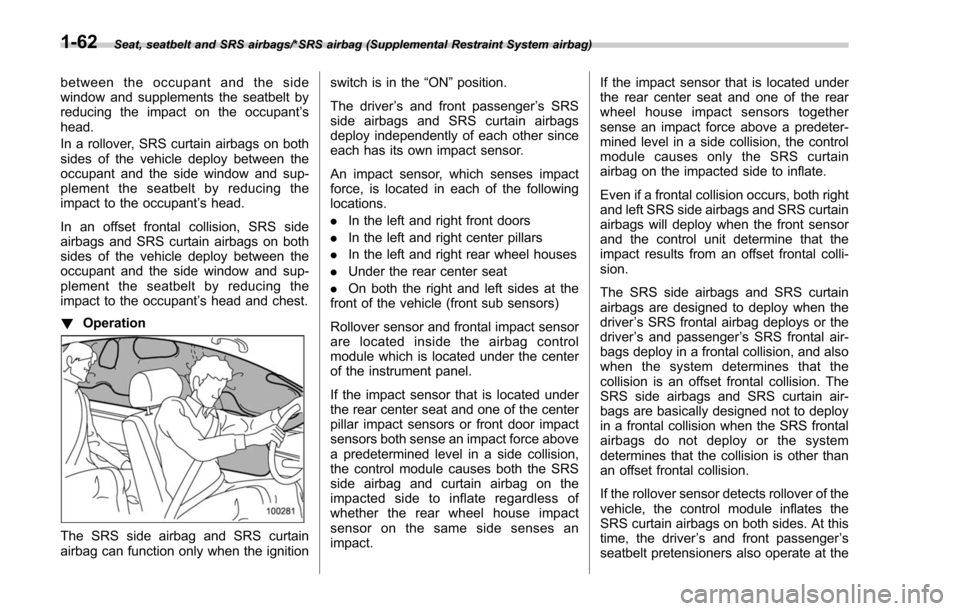
In a rollover, SRS curtain airbags on both
sides of the vehicle deploy between the
occupant and the side window and sup-
plement the seatbelt by reducing the
impact to the occupant ’s head.
In an offset frontal collision, SRS side
airbags and SRS curtain airbags on both
sides of the vehicle deploy between the
occupant and the side window and sup-
plement the seatbelt by reducing the
impact to the occupant ’s head and chest.
! Operation
The SRS side airbag and SRS curtain
airbag can function only when the ignition switch is in the
“ON”position.
The driver ’s and front passenger ’s SRS
side airbags and SRS curtain airbags
deploy independently of each other since
each has its own impact sensor.
An impact sensor, which senses impact
force, is located in each of the following
locations.
. In the left and right front doors
. In the left and right center pillars
. In the left and right rear wheel houses
. Under the rear center seat
. On both the right and left sides at the
front of the vehicle (front sub sensors)
Rollover sensor and frontal impact sensor
are located inside the airbag control
module which is located under the center
of the instrument panel.
If the impact sensor that is located under
the rear center seat and one of the center
pillar impact sensors or front door impact
sensors both sense an impact force above
a predetermined level in a side collision,
the control module causes both the SRS
side airbag and curtain airbag on the
impacted side to inflate regardless of
whether the rear wheel house impact
sensor on the same side senses an
impact. If the impact sensor that is located under
the rear center seat and one of the rear
wheel house impact sensors together
sense an impact force above a predeter-
mined level in a side collision, the control
module causes only the SRS curtain
airbag on the impacted side to inflate.
Even if a frontal collision occurs, both right
and left SRS side airbags and SRS curtain
airbags will deploy when the front sensor
and the control unit determine that the
impact results from an offset frontal colli-
sion.
The SRS side airbags and SRS curtain
airbags are designed to deploy when the
driver
’s SRS frontal airbag deploys or the
driver ’s and passenger ’s SRS frontal air-
bags deploy in a frontal collision, and also
when the system determines that the
collision is an offset frontal collision. The
SRS side airbags and SRS curtain air-
bags are basically designed not to deploy
in a frontal collision when the SRS frontal
airbags do not deploy or the system
determines that the collision is other than
an offset frontal collision.
If the rollover sensor detects rollover of the
vehicle, the control module inflates the
SRS curtain airbags on both sides. At this
time, the driver ’s and front passenger ’s
seatbelt pretensioners also operate at the
1-62
Page 169 of 634
Instruments and controls/Warning and indicator lights
If the engine coolant temperature in-
creases over the specified range, the
indicator light/warning light blinks in
RED. At this time, the engine is close to
overheating.
If the engine coolant temperature in-
creases further, the indicator light/warning
light illuminates in REDcontinuously. At
this time, the engine may be overheating.
When the indicator light/warning light
blinks in REDor illuminates in RED, safely
stop the vehicle as soon as possible, and
refer to the emergency steps to take in the
case of engine overheating. Refer to
“ Engine overheating ”F 9-12. After that,
have the system checked by your nearest
SUBARU dealer.
Also, if the indicator light/warning light
often blinks in RED, the electrical system
may be malfunctioning. Contact your
SUBARU dealer for an inspection.
NOTE
If the engine is restarted after a certain
driving condition, this indicator light/
warning light may illuminate in RED.
However, this is not a malfunction if the
indicator light/warning light turns off
after a short time.
&Charge warning light
If this light illuminates when the engine is
running, it may indicate that the charging
system is not working properly.
If the light illuminates while driving or does
not turn off after the engine starts, stop the
engine at the first safe opportunity and
check the alternator belt. If the belt is
loose, broken or if the belt is in good
condition but the light remains illuminated,
contact your nearest SUBARU dealer
immediately.
&Oil pressure warning
light
If this light illuminates when the engine is
running, it may indicate that the engine oil
pressure is low and the lubricating system
is not working properly.
If the light illuminates while driving or does
not turn off after the engine starts, stop the
engine at the first safe opportunity and
check the engine oil level. If the oil level is
low, add oil immediately. If the engine oil is
at the proper level but the light remains
illuminated, contact your nearest
SUBARU dealer immediately.
For details about checking the engine oil
level or adding the engine oil, refer to
“Engine oil ”F 11-10.
CAUTION
Do not operate the engine with the
oil pressure warning light illumi-
nated. This may cause serious en-
gine damage.
&Engine low oil level
warning light
This light illuminates when the engine oil
level decreases to the lower limit.
If the engine low oil level warning light
illuminates while driving, park the vehicle
in a safe and level location, and then
check the engine oil level. When the
engine oil level is not within the normal
range, refill with engine oil. Refer to
“Engine oil ”F 11-10.
If the warning light does not turn off after
refilling the engine oil, or the warning light
illuminates even though the engine oil
level is within the normal range, have the
vehicle checked by a SUBARU dealer.
NOTE
. After replacing or adding the engine
oil, if the engine oil level is within the
normal range when restarting the en-
gine on a level surface, the warning
light will turn off.
3-18
Page 172 of 634
&ABS warning light
CAUTION
.If any of the following conditions
occur, we recommend that you
have the ABS repaired at the first
available opportunity by your
SUBARU dealer.
– The warning light does not
illuminate when the ignition
switch is turned to the “ON ”
position.
– The warning light illuminates
when the ignition switch is
turned to the “ON ”position,
but it does not turn off even
when the vehicle speed ex-
ceeds approximately 25 mph
(40 km/h).
– The warning light illuminates
during driving.
. When the warning light is on (and
the brake system warning light is
off), the ABS function shuts
down. However, the conventional
brake system continues to oper-
ate normally.
The ABS warning light illuminates to-
gether with the brake system warning light if the EBD system malfunctions. For
further details of the EBD system mal-
function warning, refer to
“Electronic
Brake Force Distribution (EBD) system
warning ”F 3-22.
NOTE
If the warning light behavior is as
described in the following conditions,
the ABS may be considered normal.
. The warning light illuminates when
the ignition switch is turned to the
“ ON ”position and turns off approxi-
mately 2 seconds after the engine has
started.
. The warning light illuminates right
after the engine is started but turns off
immediately, remaining off.
. The warning light remains illumi-
nated after the engine has been started,
but it turns off when the vehicle speed
reaches approximately 25 mph (40
km/h).
. The warning light illuminates during
driving, but it turns off immediately and
remains off.
When driving with an insufficient battery
voltage such as when the engine is jump
started, the ABS warning light may illumi-
nate. This is due to the low battery voltage
and does not indicate a malfunction.
When the battery becomes fully charged, the light will turn off.
&Brake system
warning light
The light illuminates with the parking
brake applied while the ignition switch is
in the
“ON”position. It turns off when the
parking brake is fully released.
WARNING
. Driving with the brake system
warning light on is dangerous.
This indicates your brake system
may not be working properly. If
the light remains illuminated,
have the brakes inspected by a
SUBARU dealer immediately.
. If at all in doubt about whether
the brakes are operating prop-
erly, do not drive the vehicle.
Have your vehicle towed to the
nearest SUBARU dealer for re-
pair.
The brake system warning light has the
following functions.
! Brake fluid level warning
This light illuminates when the brake fluid
level has dropped to near the “MIN”level
of the brake fluid reservoir with the ignition
Instruments and controls/Warning and indicator lights
–CONTINUED –3-21
Page 175 of 634
Instruments and controls/Warning and indicator lights
At this time, there will be more resis-
tance when steering. However this is
not a malfunction. Normal steering
force will be restored after the steering
wheel is not operated for a while and
the power steering control system has
an opportunity to cool down. However,
if the power steering is operated in a
non-standard way which causes power
assist limitation to occur too fre-
quently, that may result in a malfunc-
tion of the power steering control
system.
&Vehicle Dynamics
Control warning light/
Vehicle Dynamics Con-
trol operation indicator
light
!Vehicle Dynamics Control warning
light
CAUTION
The Vehicle Dynamics Control sys-
tem provides its ABS control
through the electrical circuit of the
ABS. Accordingly, if the ABS is
inoperative, the Vehicle Dynamics
Control system becomes unable to provide ABS control. As a result, the
Vehicle Dynamics Control system
also becomes inoperative, causing
the warning light to illuminate.
Although both the Vehicle Dynamics
Control system and ABS are inop-
erative in this case, the ordinary
functions of the brake system are
still available. You will be safe while
driving with this condition, but drive
carefully and have your vehicle
checked at a SUBARU dealer as
soon as possible.
NOTE
.
If the electrical circuit of the Vehicle
Dynamics Control system itself mal-
functions, the warning light only illumi-
nates. At this time, the ABS (Anti-lock
Brake System) remains fully opera-
tional.
. The warning light illuminates when
the electronic control system of the
ABS/Vehicle Dynamics Control system
malfunctions.
The Vehicle Dynamics Control system is
probably inoperative under any of the
following conditions. Have your vehicle
checked at a SUBARU dealer immedi-
ately.
. The warning light does not illuminate when the ignition switch is turned to the
“ON
”position.
. The warning light illuminates while the
vehicle is running.
NOTE
If the warning light behavior is as
described in the following examples,
the Vehicle Dynamics Control system
may be considered normal.
. The warning light illuminates when
the ignition switch is turned to the
“ ON ”position and turns off approxi-
mately 2 seconds after the engine has
started.
. The warning light illuminates right
after the engine is started but turns off
immediately, remaining off.
. The warning light illuminates after
the engine has started and turns off
while the vehicle is subsequently being
driven.
. The warning light illuminates during
driving, but it turns off immediately and
remains off.
. The warning light illuminates when
the engine has stalled and continues to
illuminate after the engine has been
restarted. However, it will turn off once
the vehicle starts moving.
3-24
Page 195 of 634
Instruments and controls/Multi function display
!Default Settings
Select “Ye s ”to use the menu screen to
restore customized settings to the factory
default settings. Select “No”to return to
the previous screen without restoring the
factory default settings.Multi function display (if
equipped)
NOTE
. If your vehicle is equipped with an
information display (monochrome), re-
fer to “Information display (Mexico-
spec. models) ”F 3-34.
. Illustrations show the display for
U.S.-spec. models as an example. For
models other than U.S.-spec. models,
elements in the illustrations (such as
the display indication and measure-
ment unit) may be different than the
ones for U.S.-spec. models.
. When the vehicle is in motion,
certain functions and selections may
not be available.
WARNING
Always pay adequate attention to
safe driving when operating the
multi function display while the
vehicle is in motion. When operation
of the multi function display is
disturbing your awareness and abil-
ity to concentrate on driving, stop
the vehicle in a safe place before
performing operations on the
screen. Also, do not concentrate
on the display while driving. Doing so may cause you to look away from
the road and could result in an
accident.
The multi function display has the follow-
ing functions.
Description Page
Displays useful messages,
such as warning information,
etc. 3-48
Displays basic screens (e.g.
fuel consumption screen, etc.) 3-48
Sets and adjusts maintenance
notification 3-76
Registers driving history 3-79
Sets and customizes car op-
eration 3-80
Reverse Automatic Braking
system display (if equipped) 7-66
Also, the multi function display can also be
used to set and initialize the multi function
display itself.
3-44
Page 202 of 634
!ECO history screen
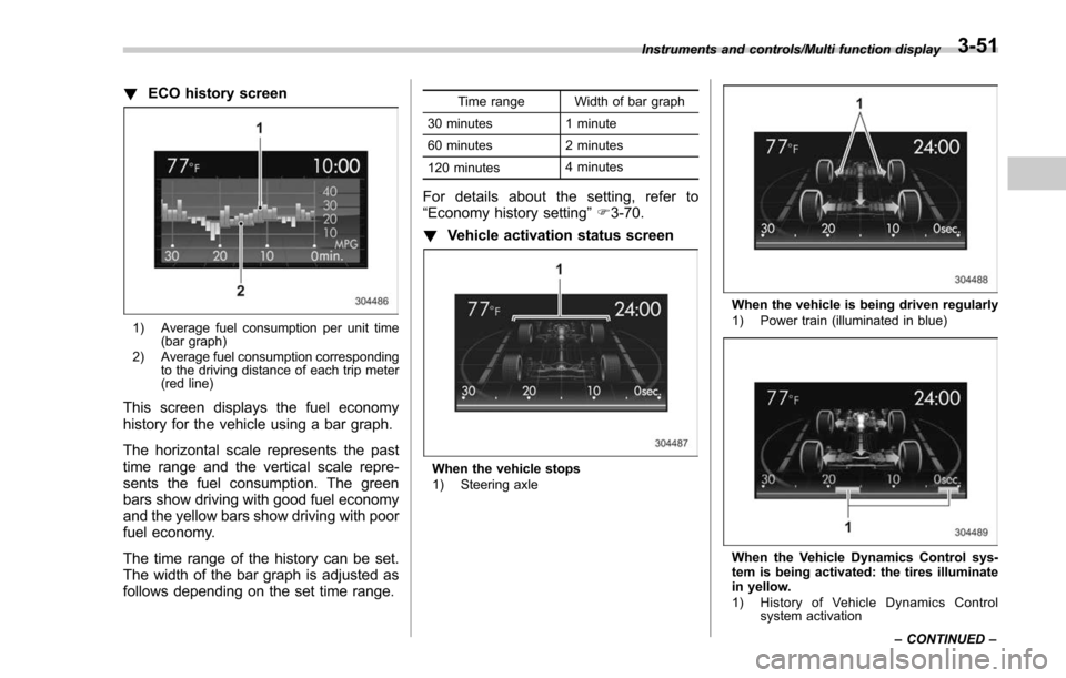
1) Average fuel consumption per unit time
(bar graph)
2) Average fuel consumption corresponding to the driving distance of each trip meter
(red line)
This screen displays the fuel economy
history for the vehicle using a bar graph.
The horizontal scale represents the past
time range and the vertical scale repre-
sents the fuel consumption. The green
bars show driving with good fuel economy
and the yellow bars show driving with poor
fuel economy.
The time range of the history can be set.
The width of the bar graph is adjusted as
follows depending on the set time range.
Time range Width of bar graph
30 minutes 1 minute
60 minutes 2 minutes
120 minutes 4 minutes
For details about the setting, refer to
“Economy history setting
”F 3-70.
! Vehicle activation status screen
When the vehicle stops
1) Steering axle
When the vehicle is being driven regularly
1) Power train (illuminated in blue)
When the Vehicle Dynamics Control sys-
tem is being activated: the tires illuminate
in yellow.
1) History of Vehicle Dynamics Control
system activation
Instruments and controls/Multi function display
–CONTINUED –
3-51
Page 263 of 634
Instruments and controls/Mirrors
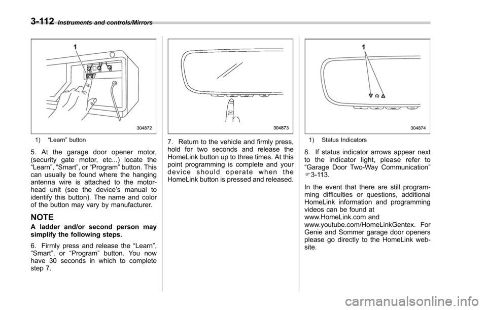
1)“Learn ”button
5. At the garage door opener motor,
(security gate motor, etc...) locate the
“Learn ”,“Smart ”,or“Program ”button. This
can usually be found where the hanging
antenna wire is attached to the motor-
head unit (see the device ’s manual to
identify this button). The name and color
of the button may vary by manufacturer.
NOTE
A ladder and/or second person may
simplify the following steps.
6. Firmly press and release the “Learn ”,
“ Smart ”,or “Program ”button. You now
have 30 seconds in which to complete
step 7.
7. Return to the vehicle and firmly press,
hold for two seconds and release the
HomeLink button up to three times. At this
point programming is complete and your
device should operate when the
HomeLink button is pressed and released.1) Status Indicators
8. If status indicator arrows appear next
to the indicator light, please refer to
“Garage Door Two-Way Communication ”
F 3-113.
In the event that there are still program-
ming difficulties or questions, additional
HomeLink information and programming
videos can be found at
www.HomeLink.com and
www.youtube.com/HomeLinkGentex. For
Genie and Sommer garage door openers
please go directly to the HomeLink web-
site.
3-112
Page 283 of 634
Climate control/Operating tips for heater and air conditioner
Operating tips for heater and
air conditioner
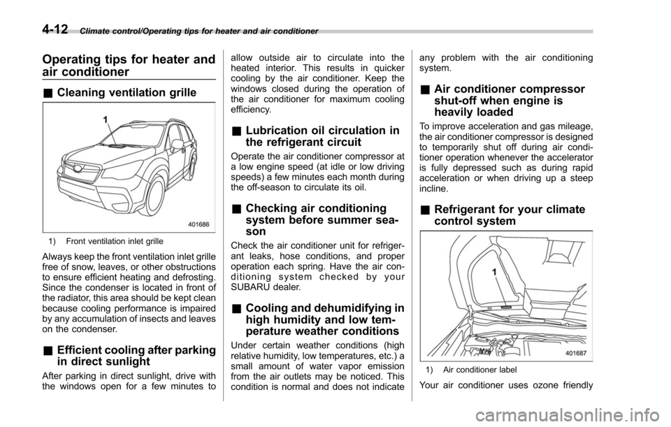
&Cleaning ventilation grille
1) Front ventilation inlet grille
Always keep the front ventilation inlet grille
free of snow, leaves, or other obstructions
to ensure efficient heating and defrosting.
Since the condenser is located in front of
the radiator, this area should be kept clean
because cooling performance is impaired
by any accumulation of insects and leaves
on the condenser.
&Efficient cooling after parking
in direct sunlight
After parking in direct sunlight, drive with
the windows open for a few minutes to allow outside air to circulate into the
heated interior. This results in quicker
cooling by the air conditioner. Keep the
windows closed during the operation of
the air conditioner for maximum cooling
efficiency.
&
Lubrication oil circulation in
the refrigerant circuit
Operate the air conditioner compressor at
a low engine speed (at idle or low driving
speeds) a few minutes each month during
the off-season to circulate its oil.
&Checking air conditioning
system before summer sea-
son
Check the air conditioner unit for refriger-
ant leaks, hose conditions, and proper
operation each spring. Have the air con-
ditioning system checked by your
SUBARU dealer.
&Cooling and dehumidifying in
high humidity and low tem-
perature weather conditions
Under certain weather conditions (high
relative humidity, low temperatures, etc.) a
small amount of water vapor emission
from the air outlets may be noticed. This
condition is normal and does not indicate any problem with the air conditioning
system.
&
Air conditioner compressor
shut-off when engine is
heavily loaded
To improve acceleration and gas mileage,
the air conditioner compressor is designed
to temporarily shut off during air condi-
tioner operation whenever the accelerator
is fully depressed such as during rapid
acceleration or when driving up a steep
incline.
&Refrigerant for your climate
control system
1) Air conditioner label
Your air conditioner uses ozone friendly
4-12
Page 288 of 634
Antenna................................................................ 5-2Roof antenna ...................................................... 5-2
Audio set............................................................. 5-2Base display audio set (if equipped) .................... 5-3
STARLINKTM7.0 Multimedia Plus audio set
(U.S. spec. models only, if equipped) ................. 5-5
Tips for operating the audio/visual system ........... 5-6
Basic information before use .............................. 5-14
Basic operation .................................................. 5-17
Unit settings ...................................................... 5-18
SUBARU STARLINK (if equipped) ....................... 5-25
AM/FM radio ....................................................... 5-27
SiriusXM Satellite Radio (if equipped) ................. 5-36
aha
TMby HARMAN ............................................. 5-43
Pandora®(if equipped) ....................................... 5-49
CD ..................................................................... 5-52
USB memory ...................................................... 5-54
iPod ................................................................... 5-55
Bluetooth audio .................................................. 5-57
AUX ................................................................... 5-60
Steering switches for audio .............................. 5-62
Bluetooth®settings ............................................ 5-65Regulatory information ....................................... 5-65 Registering/connecting Bluetooth
®device
.......... 5-65
Setting Bluetooth details .................................... 5-68
Hands-free phone system ................................. 5-70Control screen................................................... 5-71
Registering/connecting a Bluetooth phone ......... 5-72
Using the phone switch/microphone ................... 5-72
How to change the hands-free phone system ..... 5-72
Making a call ..................................................... 5-73
Receiving a call ................................................. 5-76
Talking on the phone ......................................... 5-77
Phone settings .................................................. 5-78
Voice command system .................................... 5-80Using the voice command system ...................... 5-81
Voice command system operation ...................... 5-82
Command list .................................................... 5-84
What to do if.... ................................................... 5-88Troubleshooting ................................................. 5-88
Appendix............................................................ 5-92Certification ....................................................... 5-92
Certification for the Hands-free system ............... 5-92
Certification for Mexico models .......................... 5-93
Audio
5