SUBARU IMPREZA 2016 5.G Owners Manual
Manufacturer: SUBARU, Model Year: 2016, Model line: IMPREZA, Model: SUBARU IMPREZA 2016 5.GPages: 594, PDF Size: 5.36 MB
Page 381 of 594
Interior equipment/Rear view camera
.Since the range of the image on
the monitor is limited, you should
always check the rear view and
the surrounding area with your
eyes and mirrors, and move
backward at a slow speed. Mov-
ing backward only by checking
the rear view image from the
camera could cause an accident.
. Do not disassemble or modify the
camera, switch or wiring. If
smoke comes out or you smell
a strange odor, stop using the
rear view camera immediately.
Contact your SUBARU dealer
for an inspection. Continued use
may result in accident, fire or
electric shock.
CAUTION
. If your vehicle is washed with a
high-pressure washer, do not
allow water to contact the camera
directly. Entry of water in the
camera lens may result in con-
densation, malfunction, fire or
electric shock.
. Since the camera is a precision
device, do not subject it to strong
impacts. Otherwise, malfunction, fire or electric shock may occur.
. If mud or snow sticks to or is
frozen on the camera, you must
be very careful when removing it.
Otherwise, damage to the camera
may cause a fire or electric
shock. Pour water or lukewarm
water over the camera to remove
mud and ice, and wipe it with a
soft, dry cloth.
. Do not put a flame close to the
camera or wiring. Otherwise, da-
mage or fire may occur.
. When replacing the fuse, be sure
to use a fuse with the specified
rating. Use of a fuse with a
different rating may result in a
malfunction.
. If the rear view camera is used for
a long time while the engine is
not operated, the battery may
become completely discharged.
NOTE
. Do not wipe the camera with alcohol,
benzine or paint thinner. Otherwise,
discoloration may occur. To remove
contamination, wipe the camera with a
cloth moistened with a diluted neutral
detergent and then wipe it with a soft, dry cloth.
.
When waxing the vehicle, be careful
not to apply the wax to the camera. If it
comes in contact with the camera,
moisten a clean cloth with a diluted
neutral detergent to remove the wax.
. The camera lens has a hard coating
to help prevent scratches. However,
when washing the vehicle or cleaning
the camera lens, be careful not to
scratch the camera lens. Do not use a
washing brush directly on the camera
lens. The image quality of the rear view
camera may deteriorate.
. Strong light shined on the camera
lens may develop vertical lines around
the light source. This is not a malfunc-
tion.
. Under fluorescent light, the display
may flicker. However, this is not a
malfunction.
. The image of the rear view camera
may be slightly different from the
actual color of the objects.
6-16
Page 382 of 594
&How to use the rear view
camera
When the shift lever/select lever is set to
“R”, the rear view camera automatically
displays the rear view image from the
vehicle. When the lever is set to other
positions, the image before setting to “R”
is displayed.
1. Set the ignition switch to “ON”.
2. Set the shift lever/select lever to “R”.
NOTE
. For models with the genuine
SUBARU navigation system, while the
navigation system is activated, the
image of the rear view camera will not
be displayed. However, the image of
the rear view camera has priority over
other screen displays.
. The image of the rear view camera is
horizontally reversed as is the case
with the vehicle rearview mirror or the
side view mirror.
. It may be difficult to see the image of
the rear view camera in the following
cases. This is not a malfunction of the
camera.
–The vehicle is in a dark place (at
night, in a tunnel, etc.).
– The vehicle is in an extremely hot
or cold place. –
An object (such as raindrops,
snow, dirt, etc.) that disturbs the
view of the rear view camera sticks
to the lens of the camera.
– Strong light shined directly on
the camera lens (occasionally, there
are vertical lines on the screen).
& Viewing range on the screen
CAUTION
The range that can be viewed with
the rear view camera is limited.
Always be sure to check with your
eyes when moving backward and
proceed slowly.
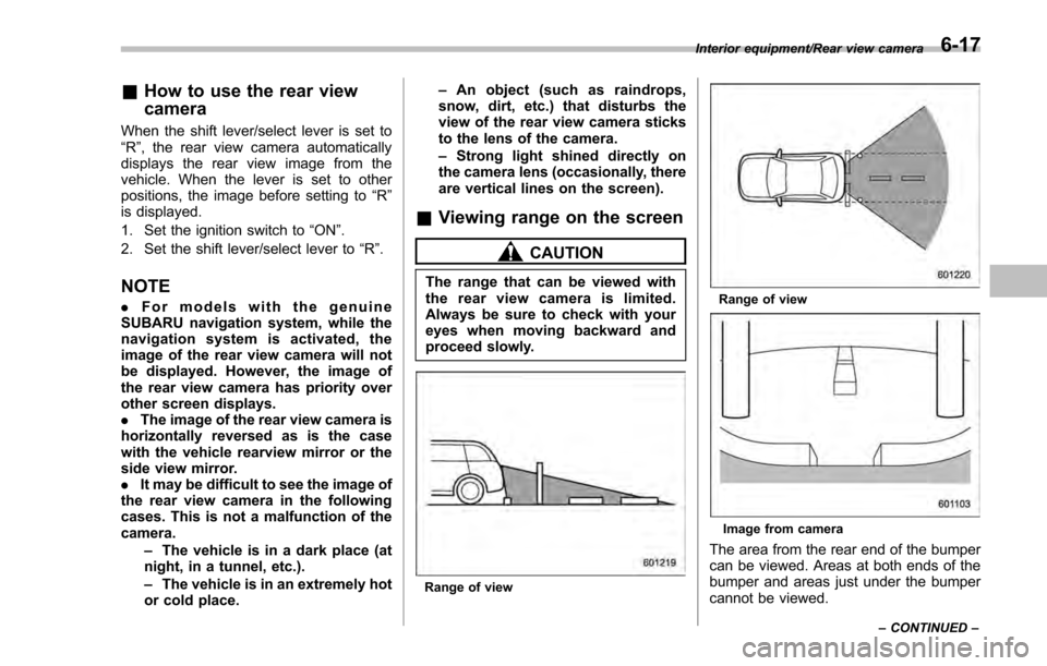
Range of view
Range of view
Image from camera
The area from the rear end of the bumper
can be viewed. Areas at both ends of the
bumper and areas just under the bumper
cannot be viewed.
Interior equipment/Rear view camera
–CONTINUED –6-17
Page 383 of 594
Interior equipment/Rear view camera
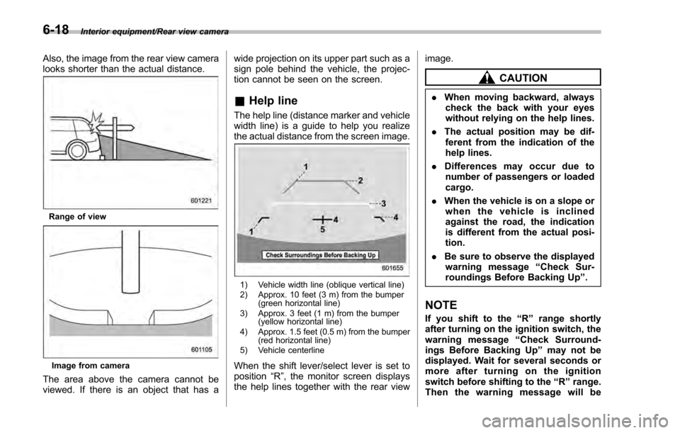
Also, the image from the rear view camera
looks shorter than the actual distance.
Range of view
Image from camera
The area above the camera cannot be
viewed. If there is an object that has awide projection on its upper part such as a
sign pole behind the vehicle, the projec-
tion cannot be seen on the screen.
&
Help line
The help line (distance marker and vehicle
width line) is a guide to help you realize
the actual distance from the screen image.
1) Vehicle width line (oblique vertical line)
2) Approx. 10 feet (3 m) from the bumper
(green horizontal line)
3) Approx. 3 feet (1 m) from the bumper (yellow horizontal line)
4) Approx. 1.5 feet (0.5 m) from the bumper (red horizontal line)
5) Vehicle centerline
When the shift lever/select lever is set to
position “R”, the monitor screen displays
the help lines together with the rear view image.
CAUTION
.
When moving backward, always
check the back with your eyes
without relying on the help lines.
. The actual position may be dif-
ferent from the indication of the
help lines.
. Differences may occur due to
number of passengers or loaded
cargo.
. When the vehicle is on a slope or
when the vehicle is inclined
against the road, the indication
is different from the actual posi-
tion.
. Be sure to observe the displayed
warning message “Check Sur-
roundings Before Backing Up ”.
NOTE
If you shift to the“R”range shortly
after turning on the ignition switch, the
warning message “Check Surround-
ings Before Backing Up ”may not be
displayed. Wait for several seconds or
more after turning on the ignition
switch before shifting to the “R”range.
Then the warning message will be
6-18
Page 384 of 594
displayed.
!Difference between screen image
and actual road
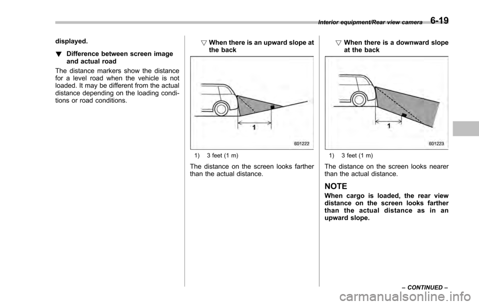
The distance markers show the distance
for a level road when the vehicle is not
loaded. It may be different from the actual
distance depending on the loading condi-
tions or road conditions. !
When there is an upward slope at
the back
1) 3 feet (1 m)
The distance on the screen looks farther
than the actual distance. !
When there is a downward slope
at the back
1) 3 feet (1 m)
The distance on the screen looks nearer
than the actual distance.
NOTE
When cargo is loaded, the rear view
distance on the screen looks farther
thantheactualdistanceasinan
upward slope.
Interior equipment/Rear view camera
–CONTINUED –6-19
Page 385 of 594
Interior equipment/Rear view camera
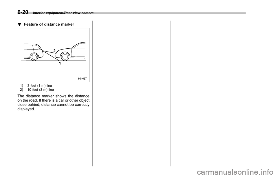
!Feature of distance marker
1) 3 feet (1 m) line
2) 10 feet (3 m) line
The distance marker shows the distance
on the road. If there is a car or other object
close behind, distance cannot be correctly
displayed.
6-20
Page 386 of 594
Fuel...................................................................... 7-3Fuel requirements ............................................... 7-3
Fuel filler lid and cap ........................................... 7-4
State emission testing (U.S. only) ...................... 7-7
Preparing to drive ............................................... 7-8
Starting and stopping the engine (models without push-button start system) .................. 7-9
Starting engine.................................................... 7-9
Stopping the engine ........................................... 7-11
Starting and stopping engine (models with
push-button start system) .............................. 7-12
Safety precautions............................................. 7-12
Operating range for push-button start system ............................................................. 7-12
Starting engine ................................................... 7-12
Stopping engine ................................................. 7-13
When access key does not operate properly ....... 7-14
Remote engine start system (dealer
option) .............................................................. 7-14
Models with “keyless access with push-button
start system ”................................................... 7-15
Models without “keyless access with push-button
start system ”................................................... 7-16
Entering the vehicle while it is running via remote start ................................................................. 7-19
Entering the vehicle following remote engine start shutdown ......................................................... 7-19
Pre-heating or pre-cooling the interior of the vehicle ............................................................. 7-19
Service mode (models without “keyless access
with push-button start system ”)........................ 7-19 Remote transmitter program (models without
“keyless access with push-button start
system ”).......................................................... 7-19
System maintenance .......................................... 7-20
Manual transmission ......................................... 7-22Shifting speeds.................................................. 7-22
Driving tips ........................................................ 7-23
Continuously variable transmission ................. 7-23Continuously variable transmission features . ..... 7-24
Select lever ....................................................... 7-24
Selection of manual mode (if equipped) .............. 7-26
Selection of “L”(if equipped) ... .......................... 7-28
Shift lock function ............................................. 7-28
Driving tips ........................................................ 7-29
Power steering ................................................... 7-30Power steering warning light .............................. 7-30
Power steering system features ......................... 7-30
Braking............................................................... 7-31Braking tips ....................................................... 7-31
Brake system .................................................... 7-31
Disc brake pad wear warning indicators ............. 7-32
ABS (Anti-lock Brake System).......................... 7-32ABS self-check.................................................. 7-32
ABS warning light .............................................. 7-33
Electronic Brake Force Distribution (EBD)
system ............................................................. 7-33
Steps to take if EBD system malfunctions .......... 7-33
Vehicle Dynamics Control system.................... 7-34Safety precautions............................................. 7-34
System features ................................................. 7-35
Vehicle Dynamics Control system monitor .......... 7-36
Starting and operating
7
Page 387 of 594
Starting and operating
Vehicle Dynamics Control OFF switch................. 7-36
Tire pressure monitoring system (TPMS)
(U.S.-spec. models) ......................................... 7-38
Parking your vehicle .......................................... 7-40
Parking brake..................................................... 7-40
Parking tips ....................................................... 7-40
Hill start assist system ...................................... 7-41To activate/deactivate the Hill start assist
system ............................................................. 7-43
Hill start assist warning light/Hill start assist OFF indicator light ................................................... 7-44
Cruise control (if equipped). .............................. 7-45To set cruise control.......................................... 7-45
To temporarily cancel the cruise control ............. 7-46To turn off the cruise control
.............................. 7-47
To change the cruising speed ............................ 7-48
Cruise control indicator light .............................. 7-50
Cruise control set indicator light ... ..................... 7-50
BSD/RCTA (5-door models—if equipped) ...... 7-50System features ................................................. 7-51
System operation ............................................... 7-52
BSD/RCTA approach indicator light/warning buzzer ............................................................. 7-54
BSD/RCTA warning indicator .............................. 7-55
BSD/RCTA OFF switch ....................................... 7-56
Certification for the BSD/RCTA ........................... 7-57
Handling of radar sensors .................................. 7-57
Page 388 of 594
Fuel
CAUTION
Use of a fuel which is low in quality
or use of an inappropriate fuel
additive may cause damage to the
engine and/or fuel system.
&Fuel requirements
The engine is designed to operate using
unleaded gasoline with an octane rating
of 87 AKI (90 RON) or higher .
! Fuel octane rating
Using a gasoline with a lower octane
rating can cause persistent and heavy
knocking, which can damage the engine.
Do not be concerned if your vehicle
sometimes knocks lightly when you drive
up a hill or when you accelerate. Contact
your SUBARU dealer if you use a fuel with
the specified octane rating and your
vehicle knocks heavily or persistently.
!RON
This octane rating is the Research Octane
Number. !
AKI
This octane rating is the average of the
Research Octane and Motor Octane
numbers and is commonly referred to as
the Anti Knock Index (AKI).
! Unleaded gasoline
The neck of the fuel filler pipe is designed
to accept only an unleaded gasoline filler
nozzle. Under no circumstances should
leaded gasoline be used because it will
damage the emission control system and
may impair driveability and fuel economy.
! Gasoline for California-certified
LEV
If your vehicle was certified to California ’s
low emission vehicle (LEV) standards as
indicated on the underhood tune-up label,
it is designed to optimize engine and
emission performance with gasoline that
meets the clean burning low-sulfur Cali-
fornia gasoline specifications. If you live in
any other state than California, your
vehicle will operate on gasoline meeting
Federal specifications. Gasoline sold out-
side California is permitted to have higher
sulfur levels, which may affect the perfor-
mance of your vehicle’ s catalytic converter
and may produce a sulfur exhaust odor or
smell. SUBARU recommends that you try
a different brand of unleaded gasoline
having lower sulfur to determine if the problem is fuel related before returning
your vehicle to an authorized dealer for
service.
!
MMT
Some gasoline contains an octane-en-
hancing additive called MMT (Methylcy-
clopentadienyl Manganese Tricarbonyl). If
you use such fuels, your emission control
system performance may deteriorate and
the CHECK ENGINE warning light/Mal-
function indicator light may turn on. If this
happens, return to your authorized
SUBARU Dealer for service. If it is
determined that the condition is caused
by the type of fuel used, repairs may not
be covered by your warranty.
! Gasoline for cleaner air
Your use of gasoline with detergent
additives will help prevent deposits from
forming in your engine and fuel system.
This helps keep your engine in tune and
your emission control system working
properly, and is a way of doing your part
for cleaner air. If you continuously use a
high quality fuel with the proper detergent
and other additives, you should never
need to add any fuel system cleaning
agents to your fuel tank.
Many gasolines are now blended with
materials called oxygenates. Use of these
fuels can also help keep the air cleaner.
Starting and operating/Fuel
–CONTINUED –7-3
Page 389 of 594
Starting and operating/Fuel
Oxygenated blend fuels, such as MTBE
(Methyl Tertiary Butyl ether) or ethanol
(ethyl or grain alcohol) may be used in
your vehicle, but should contain no more
than 15% MTBE or 10% ethanol for the
proper operation of your SUBARU.
Do not use any gasoline that contains
more than 10% ethanol, including from
any pump labeled E15, E30, E50 or E85
(which are only some examples of fuel
containing more than 10% ethanol).
In addition, some gasoline suppliers are
now producing reformulated gasolines,
which are designed to reduce vehicle
emissions. SUBARU approves the use of
reformulated gasoline.
If you are not sure what the fuel contains,
you should ask your service station
operators if their gasolines contain deter-
gents and oxygenates and if they have
been reformulated to reduce vehicle emis-
sions.
As additional guidance, only use fuels
suited for your vehicle as explained in the
following description.
.Fuel should be unleaded and have an
octane rating no lower than that specified
in this manual.
. Methanol (methyl or wood alcohol) is
sometimes mixed with unleaded gasoline. Methanol can be used in your vehicle
ONLY
if it does not exceed 5% of the fuel
mixture ANDif it is accompanied by
sufficient quantities of the proper cosol-
vents and corrosion inhibitors required to
prevent damage to the fuel system. Do not
use fuel containing methanol EXCEPT
under these conditions.
. If undesirable driveability problems are
experienced and you suspect they may be
fuel related, try a different brand of gaso-
line before seeking service at your
SUBARU dealer.
. Fuel system damage or driveability
problems which result from the use of
improper fuel are not covered under the
SUBARU Limited Warranty.
CAUTION
Do not let fuel spill on the exterior
surfaces of the vehicle. Because
fuel may damage the paint, be sure
to wipe off any spilled fuel quickly.
Paint damage caused by spilled fuel
is not covered under the SUBARU
Limited Warranty.
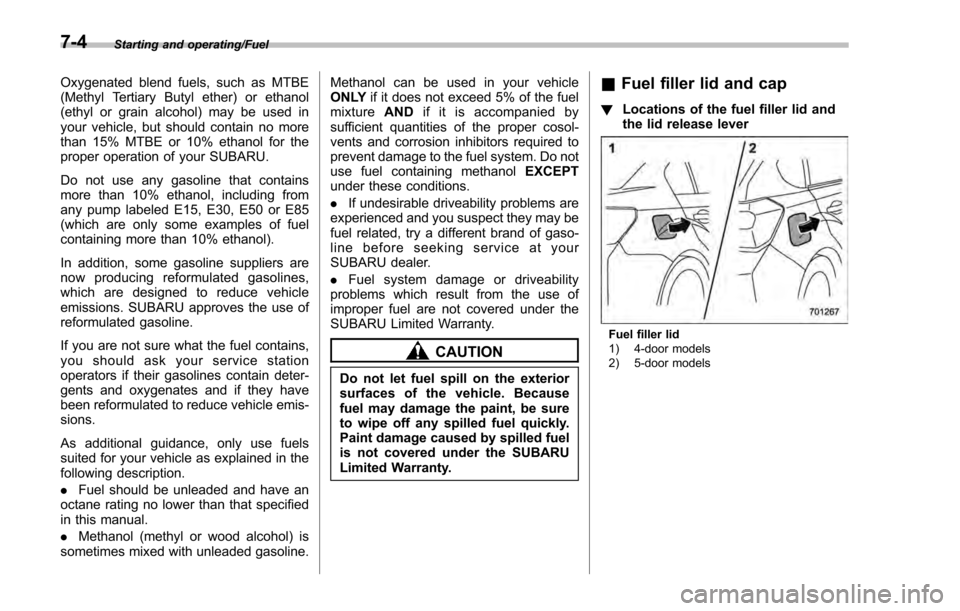
& Fuel filler lid and cap
! Locations of the fuel filler lid and
the lid release lever
Fuel filler lid
1) 4-door models
2) 5-door models
7-4
Page 390 of 594
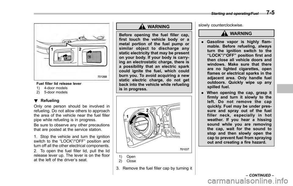
Fuel filler lid release lever
1) 4-door models
2) 5-door models
!Refueling
Only one person should be involved in
refueling. Do not allow others to approach
the area of the vehicle near the fuel filler
pipe while refueling is in progress.
Be sure to observe any other precautions
that are posted at the service station.
1. Stop the vehicle and turn the ignition
switch to the “LOCK”/“OFF ”position and
turn off all the other electrical components.
2. To open the fuel filler lid, pull the lid
release lever up. The lever is on the floor
at the left of the driver ’s seat.
WARNING
Before opening the fuel filler cap,
first touch the vehicle body or a
metal portion of the fuel pump or
similar object to discharge any
static electricity that may be present
on your body. If your body is carry-
ing an electrostatic charge, there is
a possibility that an electric spark
could ignite the fuel, which could
burn you. To avoid acquiring a new
static electric charge, do not get
back into the vehicle while refueling
is in progress.
1) Open
2) Close
3. Remove the fuel filler cap by turning it slowly counterclockwise.
WARNING
.
Gasoline vapor is highly flam-
mable. Before refueling, always
turn the ignition switch to the
“LOCK ”/“OFF ”position first and
then close all vehicle doors and
windows. Make sure that there
are no lighted cigarettes, open
flames or electrical sparks in the
adjacent area. Only handle fuel
outdoors. Quickly wipe up any
spilled fuel.
. When opening the cap, grasp it
firmly and turn it slowly to the
left. Do not remove the cap
quickly. Fuel may be under pres-
sure and spray out of the fuel
filler neck, especially in hot
weather. If you hear a hissing
sound while you are removing
the cap, wait for the sound to
stop and then slowly open the
cap to prevent fuel from spraying
out and creating a fire hazard.
Starting and operating/Fuel
–CONTINUED –7-5