reset SUBARU IMPREZA 2016 5.G Owners Manual
[x] Cancel search | Manufacturer: SUBARU, Model Year: 2016, Model line: IMPREZA, Model: SUBARU IMPREZA 2016 5.GPages: 594, PDF Size: 5.36 MB
Page 23 of 594

&Combination meter
! U.S.-spec. models (type A)
The illustration above is a typical example. For some models, the combination meter
may be slightly different than that shown in the illustration.
1) Tachometer (page 3-11)
2) Trip meter and odometer (page 3-10)
3) Select lever/gear position indicator
(page 3-30)
4) Speedometer (page 3-10)
5) Information display selection knob (page 3-32)
6) ECO gauge (page 3-12)
7) Fuel gauge (page 3-12)
8) Trip meter A/B selection and trip meter reset knob (page 3-11)
18
Page 24 of 594

!U.S.-spec. models (type B)
The illustration above is a typical example. For some models, the combination meter
may be slightly different than that shown in the illustration.
1) Tachometer (page 3-11)
2) Multi information display (page 3-38)
3) Fuel gauge (page 3-12)
4) Select lever/gear position indicator
(page 3-30)
5) Speedometer (page 3-10)
6) Information display selection knob (page 3-32)
7) ECO gauge (page 3-12)
8) Trip meter and odometer (page 3-10)
9) Trip meter A/B selection and trip meter reset knob (page 3-11)
–CONTINUED –
19
Page 25 of 594

!Except U.S.-spec. models (type A)
The illustration above is a typical example. For some models, the combination meter
may be slightly different than that shown in the illustration.
1) Tachometer (page 3-11)
2) Trip meter and odometer (page 3-10)
3) Select lever/gear position indicator
(page 3-30)
4) Speedometer (page 3-10)
5) Information display selection knob (page 3-32)
6) ECO gauge (page 3-12)
7) Fuel gauge (page 3-12)
8) Trip meter A/B selection and trip meter reset knob (page 3-11)
20
Page 26 of 594

!Except U.S.-spec. models (type B)
The illustration above is a typical example. For some models, the combination meter
may be slightly different than that shown in the illustration.
1) Tachometer (page 3-11)
2) Multi information display (page 3-38)
3) Fuel gauge (page 3-12)
4) Select lever/gear position indicator
(page 3-30)
5) Speedometer (page 3-10)
6) Trip meter A/B selection and trip meter reset knob (page 3-11)
7) ECO gauge (page 3-12)
8) Trip meter and odometer (page 3-10)
–CONTINUED –
21
Page 157 of 594
Instruments and controls/Meters and gauges
ving. The engine will resume run-
ning normally after the engine speed
is reduced below the red zone.
NOTE
To protect the engine/transmission
while the select lever is in the“P ” or
“N ”position (for CVT models) or the
shift lever is in the neutral position (for
MT models), the engine is controlled so
that the engine speed may not become
too high even if the accelerator pedal is
pressed hard.
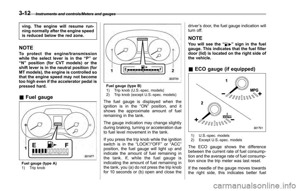
& Fuel gauge
Fuel gauge (type A)
1) Trip knob
Fuel gauge (type B)
1) Trip knob (U.S.-spec. models)
2) Trip knob (except U.S.-spec. models)
The fuel gauge is displayed when the
ignition is in the “ON”position, and it
shows the approximate amount of fuel
remaining in the tank.
The gauge indication may change slightly
during braking, turning or acceleration due
to fuel level movement in the tank.
If you press the trip knob while the ignition
switch is in the “LOCK”/ “OFF”or “ACC ”
position, the fuel gauge will light up and
indicate the amount of fuel remaining in
the tank. If, while the fuel gauge is
indicating the amount of fuel remaining in
the tank, you (a) do not press the trip knob
for 10 seconds or (b) open and close the driver
’s door, the fuel gauge indication will
turn off.
NOTE
You will see the “”sign in the fuel
gauge. This indicates that the fuel filler
door (lid) is located on the right side of
the vehicle.
& ECO gauge (if equipped)
1) U.S.-spec. models
2) Except U.S.-spec. models
The ECO gauge shows the difference
between the current rate of fuel consump-
tion and the average rate of fuel consump-
tion since the trip meter was last reset.
If the needle of the gauge moves towards
the right side, this indicates better fuel
3-12
Page 158 of 594

efficiency.
NOTE
.The ECO gauge shows only an
approximate indication of fuel effi-
ciency.
. After resetting the trip meter, the
average rate of fuel consumption is not
shown until driving 0.6 mile (1 km).
Before that time, the ECO gauge does
not operate.
Warning and indicator lights
& Initial illumination for system
check
Several of the warning and indicator lights
illuminate when the ignition switch is
initially turned to the “ON ”position. This
permits checking the operation of the
bulbs.
Apply the parking brake and turn the
ignition switch to the “ON”position. For
the system check, the following lights
illuminate and then turn off after several
seconds or after the engine has started.
: Seatbelt warning light (The seatbelt warning light turns off
only when the driver fastens the
seatbelt.)
: Front passenger ’s seatbelt warning
light
(The seatbelt warning light turns off
only when the front seat passenger
fastens the seatbelt.)
: SRS airbag system warning light
ON /
: Front passenger ’s frontal airbag
ON indicator light
/: Front passenger ’s frontal airbag
OFF indicator light
: CHECK ENGINE warning light/Mal- function indicator light
: Coolant temperature low indicator light/Coolant temperature high warn-
ing light
: Charge warning light
: Oil pressure warning light
: Engine low oil level warning light
: Windshield washer fluid warning light
: AT OIL TEMP warning light(CVT models)
: Low tire pressure warning light(U.S.- spec. models)
/: ABS warning light
/: Brake system warning light
: Low fuel warning light
: Hill start assist warning light/Hill startassist OFF indicator light
: Door open warning light
: AWD warning light (CVT models)
: Power steering warning light
: Vehicle Dynamics Control warning light/Vehicle Dynamics Control opera-
tion indicator light
Instruments and controls/Warning and indicator lights
–CONTINUED –3-13
Page 165 of 594
Instruments and controls/Warning and indicator lights
Your vehicle has also been equipped with
a TPMS malfunction indicator to indicate
when the system is not operating properly.
The TPMS malfunction indicator is com-
bined with the low tire pressure telltale.
When the system detects a malfunction,
the telltale will flash for approximately one
minute and then remain continuously
illuminated. This sequence will continue
upon subsequent vehicle start-ups as long
as the malfunction exists. When the
malfunction indicator is illuminated, the
system may not be able to detect or signal
low tire pressure as intended. TPMS
malfunctions may occur for a variety of
reasons, including the installation of re-
placement or alternate tires or wheels on
the vehicle that prevent the TPMS from
functioning properly. Always check the
TPMS malfunction telltale after replacing
one or more tires or wheels on your
vehicle to ensure that the replacement or
alternate tires and wheels allow the TPMS
to continue to function properly.
Should the warning light illuminate stea-
dily after blinking for approximately one
minute, have the system inspected by
your nearest SUBARU dealer as soon as
possible.
WARNING
If this light does not illuminatebriefly after the ignition switch is
turned ON or the light illuminates
steadily after blinking for approxi-
mately one minute, you should have
your Tire Pressure Monitoring Sys-
tem checked at a SUBARU dealer as
soon as possible.
If this light illuminates while driving,
never brake suddenly and keep
driving straight ahead while gradu-
ally reducing speed. Then slowly
pull off the road to a safe place.
Otherwise an accident involving
serious vehicle damage and serious
personal injury could occur.
If this light still illuminates while
driving after adjusting the tire pres-
sure, a tire may have significant
damage and a fast leak that causes
the tire to lose air rapidly. If you have
a flat tire, replace it with a spare tire
as soon as possible.
When a spare tire is mounted or a
wheel rim is replaced without the
original pressure sensor/transmitter
being transferred, the Low tire pres-
sure warning light will illuminate
steadily after blinking for approxi-
mately one minute. This indicates
the TPMS is unable to monitor all
four road wheels. Contact your
SUBARU dealer as soon as possiblefor tire and sensor replacement and/
or system resetting.
If the light illuminates steadily after
blinking for approximately one min-
ute, promptly contact a SUBARU
dealer to have the system inspected.
CAUTION
The tire pressure monitoring system
is NOT a substitute for manually
checking tire pressure. The tire
pressure should be checked peri-
odically (at least monthly) using a
tire gauge. After any change to tire
pressure(s), the tire pressure mon-
itoring system will not re-check tire
inflation pressures until the vehicle
is first driven more than 20 mph (32
km/h). After adjusting the tire pres-
sures, increase the vehicle speed to
at least 20 mph (32 km/h) to start the
TPMS re-checking of the tire infla-
tion pressures. If the tire pressures
are now above the severe low
pressure threshold, the low tire
pressure warning light should turn
off a few minutes later. Therefore, be
sure to install the specified size for
the front and rear tires.
3-20
Page 180 of 594
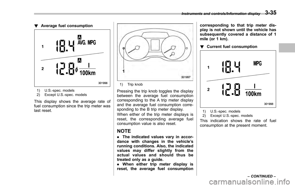
!Average fuel consumption
1) U.S.-spec. models
2) Except U.S.-spec. models
This display shows the average rate of
fuel consumption since the trip meter was
last reset.
1) Trip knob
Pressing the trip knob toggles the display
between the average fuel consumption
corresponding to the A trip meter display
and the average fuel consumption corre-
sponding to the B trip meter display.
When either of the trip meter displays is
reset, the correspon ding average fuel
consumption value is also reset.
NOTE
. The indicated values vary in accor-
dance with changes in the vehicle ’s
running conditions. Also, the indicated
values may differ slightly from the
actual values and should thus be
treated only as a guide.
. When either trip meter display is
reset, the average fuel consumption corresponding to that trip meter dis-
play is not shown until the vehicle has
subsequently covered a distance of 1
mile (or 1 km).
!
Current fuel consumption
1) U.S.-spec. models
2) Except U.S.-spec. models
This indication shows the rate of fuel
consumption at the present moment.
Instruments and controls/Information display
–CONTINUED –3-35
Page 181 of 594
Instruments and controls/Information display
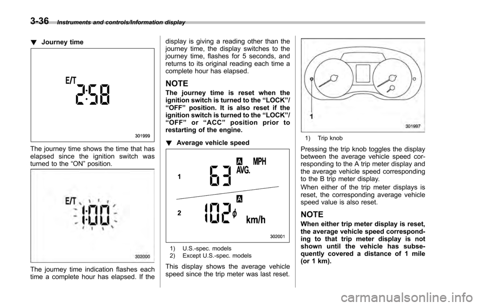
!Journey time
The journey time shows the time that has
elapsed since the ignition switch was
turned to the “ON”position.
The journey time indication flashes each
time a complete hour has elapsed. If the display is giving a reading other than the
journey time, the display switches to the
journey time, flashes for 5 seconds, and
returns to its original reading each time a
complete hour has elapsed.
NOTE
The journey time is reset when the
ignition switch is turned to the
“LOCK”/
“OFF ”position. It is also reset if the
ignition switch is turned to the “LOCK”/
“ OFF ”or “ACC” position prior to
restarting of the engine.
! Average vehicle speed
1) U.S.-spec. models
2) Except U.S.-spec. models
This display shows the average vehicle
speed since the trip meter was last reset.
1) Trip knob
Pressing the trip knob toggles the display
between the average vehicle speed cor-
responding to the A trip meter display and
the average vehicle speed corresponding
to the B trip meter display.
When either of the trip meter displays is
reset, the corresponding average vehicle
speed value is also reset.
NOTE
When either trip meter display is reset,
the average vehicle speed correspond-
ing to that trip meter display is not
shown until the vehicle has subse-
quently covered a distance of 1 mile
(or 1 km).
3-36
Page 190 of 594
NOTE
.Displaying the birthday/anniversary
screen can be set to on or off. Refer to
“Bypass screen setting” F3-72.
. Up to five items can be set for
birthdays and anniversaries respec-
tively. Refer to “Selection screen ”F 3-
54.
& Ending screen
If“Eco Summary ”is set to “On”in the
“Bypass screen setting ”, the“Fuel con-
sumption results screen” will be displayed
before the screen turns off when the
ignition switch is turned to the “LOCK” /
“ OFF ”position.
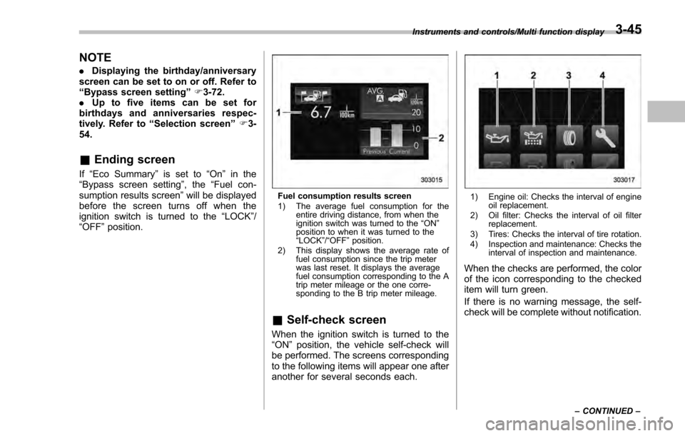
Fuel consumption results screen
1) The average fuel consumption for the
entire driving distance, from when the
ignition switch was turned to the “ON ”
position to when it was turned to the
“ LOCK ”/“ OFF ”position.
2) This display shows the average rate of fuel consumption since the trip meter
was last reset. It displays the average
fuel consumption corresponding to the A
trip meter mileage or the one corre-
sponding to the B trip meter mileage.
&Self-check screen
When the ignition switch is turned to the
“ON ”position, the vehicle self-check will
be performed. The screens corresponding
to the following items will appear one after
another for several seconds each.
1) Engine oil: Checks the interval of engine oil replacement.
2) Oil filter: Checks the interval of oil filter replacement.
3) Tires: Checks the interval of tire rotation.
4) Inspection and maintenance: Checks the interval of inspection and maintenance.
When the checks are performed, the color
of the icon corresponding to the checked
item will turn green.
If there is no warning message, the self-
check will be complete without notification.
Instruments and controls/Multi function display
–CONTINUED –3-45