warning SUBARU IMPREZA WRX 2004 2.G User Guide
[x] Cancel search | Manufacturer: SUBARU, Model Year: 2004, Model line: IMPREZA WRX, Model: SUBARU IMPREZA WRX 2004 2.GPages: 491, PDF Size: 5.93 MB
Page 56 of 491
1-29
Seat, seatbelt and SRS airbags
– CONTINUED –
your SUBARU dealer.
! System monitors
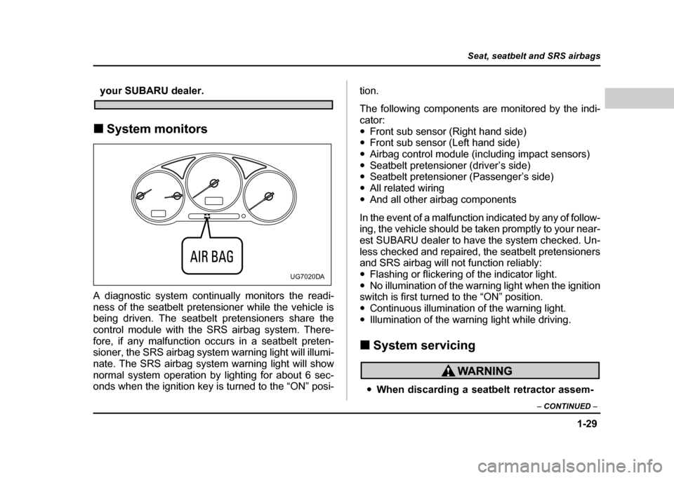
A diagnostic system continually monitors the readi-
ness of the seatbelt pretensioner while the vehicle is
being driven. The seatbelt pretensioners share the
control module with the SRS airbag system. There-
fore, if any malfunction occurs in a seatbelt preten-
sioner, the SRS airbag system warning light will illumi-
nate. The SRS airbag system warning light will show
normal system operation by lighting for about 6 sec-
onds when the ignition key is turned to the “ON” posi- tion.
The following components are monitored by the indi- cator:"
Front sub sensor (Right hand side)
" Front sub sensor (Left hand side)
" Airbag control module (including impact sensors)
" Seatbelt pretensioner (driver’s side)
" Seatbelt pretensioner (Passenger’s side)
" All related wiring
" And all other airbag components
In the event of a malfunction indicated by any of follow-
ing, the vehicle should be taken promptly to your near-
est SUBARU dealer to have the system checked. Un-
less checked and repaired, the seatbelt pretensioners
and SRS airbag will not function reliably: " Flashing or flickering of the indicator light.
" No illumination of the warning light when the ignition
switch is first turned to the “ON” position." Continuous illumination of the warning light.
" Illumination of the warning light while driving.
! System servicing
"When discarding a seatbelt retractor assem-
UG7020DA
Page 99 of 491
1-72
Seat, seatbelt and SRS airbags
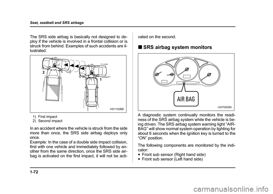
The SRS side airbag is basically not designed to de-
ploy if the vehicle is involved in a frontal collision or is
struck from behind. Examples of such accidents are il-
lustrated.
1) First impact
2) Second impact
In an accident where the vehicle is struck from the side
more than once, the SRS side airbag deploys only
once.
Example: In the case of a double side impact collision,
first with one vehicle and immediately followed by an-
other from the same direction, once the SRS side air-
bag is activated on the first impact, it will not be acti- vated on the second. !
SRS airbag system monitors
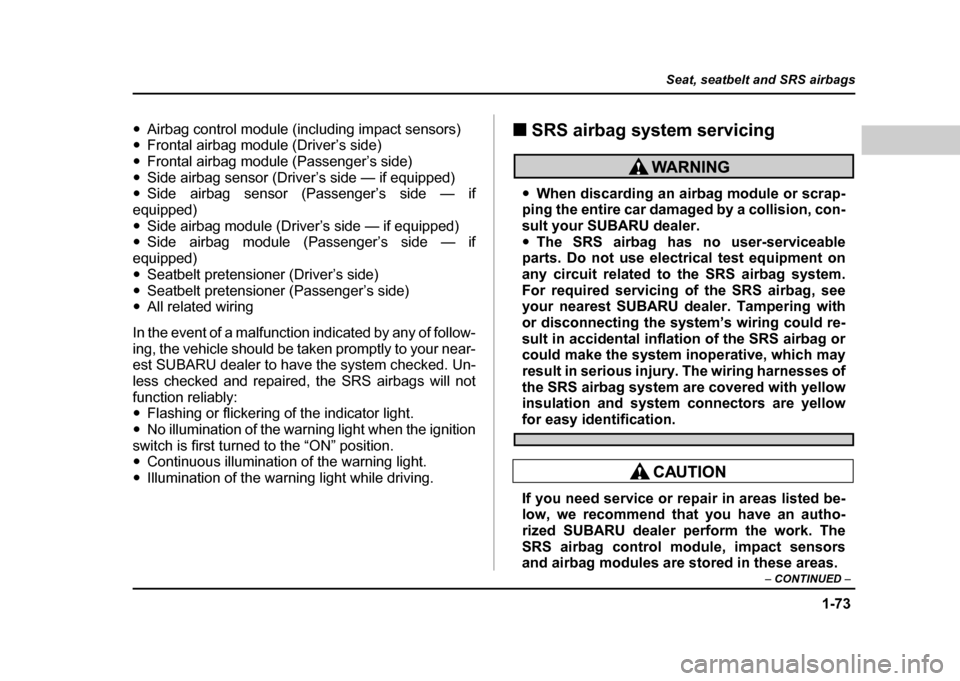
A diagnostic system continually monitors the readi-
ness of the SRS airbag system while the vehicle is be-
ing driven. The SRS airbag system warning light “AIR-
BAG” will show normal system operation by lighting for
about 6 seconds when the ignition key is turned to the“ON” position.
The following components are monitored by the indi- cator:" Front sub sensor (Right hand side)
" Front sub sensor (Left hand side)
2
1
HS1102BBUG7020DA
Page 100 of 491
1-73
Seat, seatbelt and SRS airbags
– CONTINUED –
"Airbag control module (including impact sensors)
" Frontal airbag module (Driver’s side)
" Frontal airbag module (Passenger’s side)
" Side airbag sensor (Driver’s side — if equipped)
" Side airbag sensor (Passenger’s side — if
equipped) " Side airbag module (Driver’s side — if equipped)
" Side airbag module (Passenger’s side — if
equipped)" Seatbelt pretensioner (Driver’s side)
" Seatbelt pretensioner (Passenger’s side)
" All related wiring
In the event of a malfunction indicated by any of follow-
ing, the vehicle should be taken promptly to your near-
est SUBARU dealer to have the system checked. Un-
less checked and repaired, the SRS airbags will not
function reliably: " Flashing or flickering of the indicator light.
" No illumination of the warning light when the ignition
switch is first turned to the “ON” position." Continuous illumination of the warning light.
" Illumination of the warning light while driving. !
SRS airbag system servicing
"When discarding an airbag module or scrap-
ping the entire car damaged by a collision, con-
sult your SUBARU dealer." The SRS airbag has no user-serviceable
parts. Do not use electrical test equipment on
any circuit related to the SRS airbag system.
For required servicing of the SRS airbag, see
your nearest SUBARU dealer. Tampering with
or disconnecting the system’s wiring could re-
sult in accidental inflation of the SRS airbag or
could make the system inoperative, which may
result in serious injury. The wiring harnesses of
the SRS airbag system are covered with yellow
insulation and system connectors are yellow
for easy identification.
If you need service or repair in areas listed be-
low, we recommend that you have an autho-
rized SUBARU dealer perform the work. The
SRS airbag control module, impact sensors
and airbag modules are stored in these areas.
Page 118 of 491
2-15
Keys and doors
– CONTINUED –
breaking glass or forced entry). Note that there are two
alarm levels for shock: warning and alarm. In warning
mode, the alarm detects lower level vibrations and
triggers 2 warning chirps on the horn and two flashes
on the lights as a deterrent to would be vandals. In
alarm mode, higher levels of shock are detected and
the system will go into full alarm. "Ignition switch being turned on while in armed state.
NOTE
With the valet mode selected, the security system
does not operate when the remote transmitter is
used for locking and unlocking. The security sys-
tem indicator light in the combination meter flash-
es twice per second to show that the valet mode is
selected. For details, refer to “Valet mode” in this
section. ! Arming the system
! To arm the system using remote transmitter
1. Close all windows.
2. Remove the key from the ignition switch.
3. Open the doors and get out of the vehicle.
4. Make sure that the engine hood (and the trunk lid)
are locked.
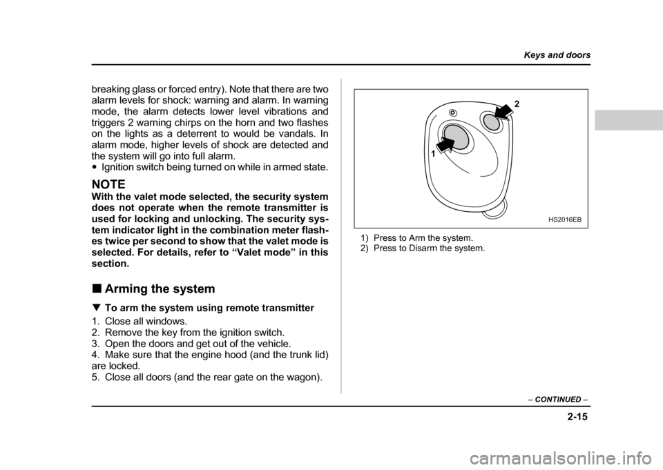
5. Close all doors (and the rear gate on the wagon). 1) Press to Arm the system.
2) Press to Disarm the system.
1
2
HS2016EB
Page 138 of 491

3-1
3
Instruments and controls
Ignition switch .............................................. 3-3 LOCK .................................................................. 3-3
ACC .................................................................... 3-4
ON ....................................................................... 3-4
START ................................................................ 3-4
Key reminder chime .......................................... 3-4
Ignition switch light (if equipped) .................... 3-5
Key interlock release (AT vehicles only) ........ 3-5
Hazard warning flasher ................................ 3-6
Meters and gauges (WRX-STi) .................... 3-7 Combination meter illumination ...................... 3-7
Cancelling sequential illumination of the combination meter ......................................... 3-7
Speedometer ..................................................... 3-7
Odometer/Trip meter ........................................ 3-8
Tachometer ........................................................ 3-9
Fuel gauge ......................................................... 3-9
Temperature gauge ........................................... 3-10
Ambient temperature gauge ............................ 3-11
REV indicator light and buzzer (WRX-STi) . 3-12 Setting the alarm-level engine speed .............. 3-13
Deactivating the REV alarm system ................ 3-14
Meters and gauges (Except WRX-STi) ........ 3-15 Speedometer ..................................................... 3-15
Odometer/Trip meter ........................................ 3-15
Tachometer ........................................................ 3-16
Fuel gauge ......................................................... 3-16
Temperature gauge ........................................... 3-17
Ambient temperature gauge (if equipped) ...... 3-18
Warning and indicator lights ....................... 3-19 Seatbelt warning light and chime .................... 3-19 SRS airbag system warning light .................... 3-20
CHECK ENGINE warning light/Malfunction
indicator lamp ................................................. 3-20
Charge warning light ........................................ 3-21
Oil pressure warning light ............................... 3-21
AT OIL TEMPerature warning light (for AT vehicles) ............................................. 3-22
Rear differential oil temperature warning light
(WRX-STi) ........................................................ 3-22
ABS warning light ............................................. 3-23
Brake system warning light ............................. 3-24
Door open warning lights ................................ 3-25
Front-wheel drive warning light (for AT vehicles – if equipped) ...................... 3-25
Intercooler water spray warning light
(WRX-STi) ........................................................ 3-25
Selector lever position indicator (AT vehicles) 3-26
Turn signal indicator lights .............................. 3-26
High beam indicator light ................................. 3-26
Cruise control indicator light ........................... 3-26
Cruise control set indicator light .................... 3-26
Driver’s control center differential auto indicator light (WRX-STi) ............................... 3-26
Driver’s control center differential indicator
lights (WRX-STi) ............................................. 3-27
Headlight indicator light (WRX-STi) ................ 3-27
REV indicator light (WRX-STi) ......................... 3-27
Clock .............................................................. 3-28
Light control switch ...................................... 3-29 Headlights ......................................................... 3-29
High/low beam change (dimmer) .................... 3-30
Headlight flasher ............................................... 3-30
Page 143 of 491
3-6
Instruments and controls
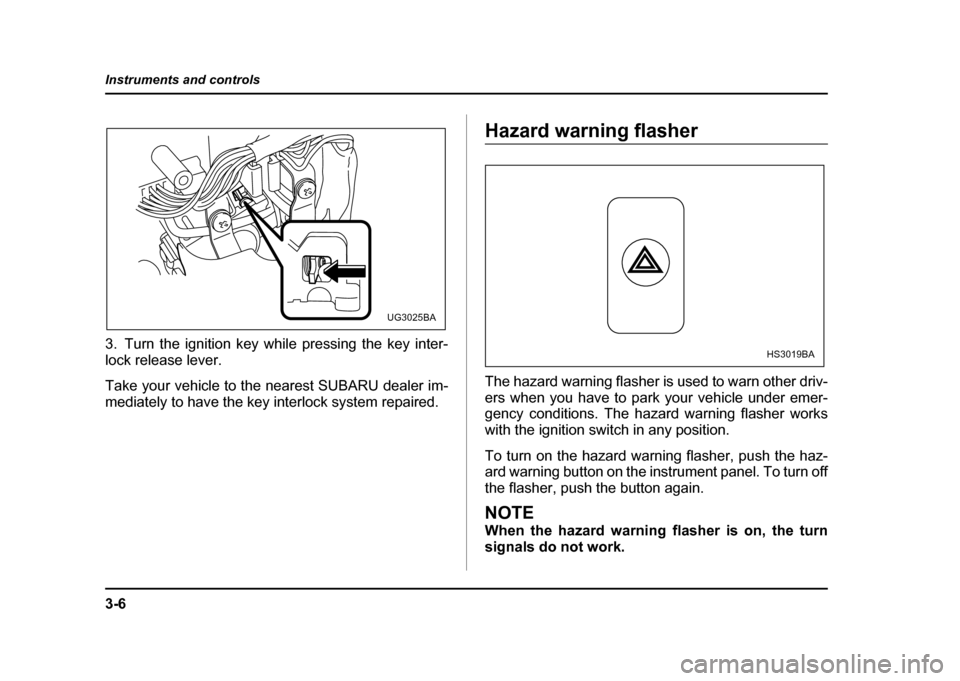
3. Turn the ignition key while pressing the key inter-
lock release lever.
Take your vehicle to the nearest SUBARU dealer im-
mediately to have the key interlock system repaired.
Hazard warning flasher
The hazard warning flasher is used to warn other driv-
ers when you have to park your vehicle under emer-
gency conditions. The hazard warning flasher works with the ignition switch in any position.
To turn on the hazard warning flasher, push the haz-
ard warning button on the instrument panel. To turn off
the flasher, push the button again.
NOTE
When the hazard warning flasher is on, the turn
signals do not work.
UG3025BA
HS3019BA
Page 146 of 491
3-9
Instruments and controls
– CONTINUED –
To set the trip meter to zero, select the A trip or B trip
meter by pushing the knob and keep the knob pushed for more than 2 seconds.
To ensure safety, do not attempt to change the
function of the indicator during driving, as an
accident could result.
NOTE
If the connection between the combination meter
and battery is broken for any reason such as vehi-
cle maintenance or fuse replacement, the data re-
corded on the trip meter will be lost. !Tachometer
The tachometer shows the engine speed in thousands
of revolutions per minute.
Do not operate the engine with the pointer of the tachometer in the red zone. In this range, fuel injection will be cut by the engine control
module to protect the engine from overrevving.
The engine will resume running normally after
the engine speed is reduced below the red
zone.
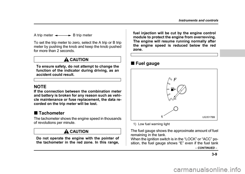
! Fuel gauge
1) Low fuel warning light
The fuel gauge shows the approximate amount of fuel
remaining in the tank.
When the ignition switch is in the “LOCK” or “ACC” po-
sition, the fuel gauge shows “E” even if the fuel tank
A trip meter B trip meter
1UG3517BB
Page 147 of 491
3-10
Instruments and controls
contains fuel.
The gauge may move slightly during braking, turning
or acceleration due to fuel level movement in the tank.
NOTE
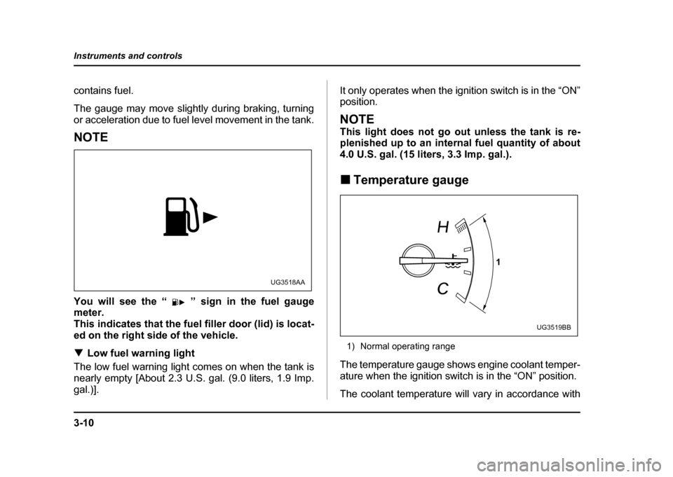
You will see the “ ” sign in the fuel gauge
meter.
This indicates that the fuel filler door (lid) is locat-
ed on the right side of the vehicle. !
Low fuel warning light
The low fuel warning light comes on when the tank is
nearly empty [About 2.3 U.S. gal. (9.0 liters, 1.9 Imp.
gal.)]. It only operates when the ignition switch is in the “ON” position.
NOTE
This light does not go out unless the tank is re-
plenished up to an internal fuel quantity of about
4.0 U.S. gal. (15 liters, 3.3 Imp. gal.). !
Temperature gauge
1) Normal operating range
The temperature gauge shows engine coolant temper-
ature when the ignition switch is in the “ON” position.
The coolant temperature will vary in accordance with
UG3518AA
1
UG3519BB
Page 149 of 491
3-12
Instruments and controls
"
When the actual ambient temperature falls outside
the specified gauge range. REV indicator light and buzzer (WRX-
STi)
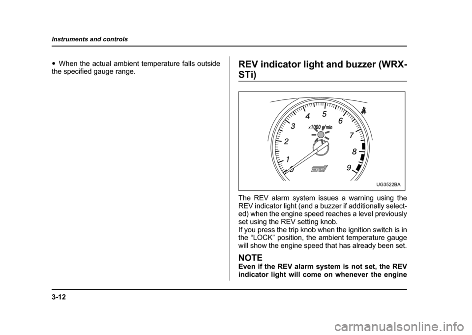
The REV alarm system issues a warning using the
REV indicator light (and a buzzer if additionally select-
ed) when the engine speed reaches a level previously
set using the REV setting knob.
If you press the trip knob when the ignition switch is in
the “LOCK” position, the ambient temperature gauge
will show the engine speed that has already been set.
NOTE
Even if the REV alarm system is not set, the REV
indicator light will come on whenever the engine
UG3522BA
Page 151 of 491

3-14
Instruments and controls
gine-speed warnings are given by both the REV in-
dicator light and the buzzer. "
Turn the knob counterclockwise ( −) to disable the
buzzer. The indicator will show “– –”, and the buzzer
will not sound. With the buzzer disabled, engine-
speed warnings are given only by the REV indicator
light.
Approximately three seconds after you stop turning
the knob, the buzzer will sound once to indicate the
end of the setting procedure. The indicator will return
to showing the ambient temperature.
Also, the tachometer needle will return to approxi- mately “0”.
NOTE " The REV alarm system does not operate while
settings are being entered. " The speed-setting mode terminates if 0 rpm is
selected." The speed-setting mode is canceled if the igni-
tion switch is turned to OFF or the vehicle starts
moving before the setting procedure is finished. " Speed setting is impossible when the vehicle is
moving. " The set engine speed may differ from the engine
speed shown by the tachometer. Use the engine
speed shown by the tachometer as a rough guide. !
Deactivating the REV alarm system
To deactivate the REV alarm system’s REV indicator
light and buzzer functions, set the alarm-level engine
speed to 0 (zero) rpm.