height SUBARU LEGACY 1996 Service Repair Manual
[x] Cancel search | Manufacturer: SUBARU, Model Year: 1996, Model line: LEGACY, Model: SUBARU LEGACY 1996Pages: 2890, PDF Size: 61.9 MB
Page 311 of 2890
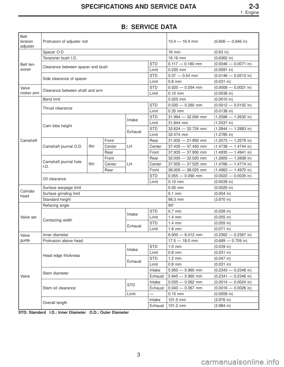
B: SERVICE DATA
Belt
tension
adjusterProtrusion of adjuster rod 15.4—16.4 mm (0.606—0.646 in)
Belt ten-
sionerSpacer O.D. 16 mm (0.63 in)
Tensioner bush I.D. 16.16 mm (0.6362 in)
Clearance between spacer and bushSTD 0.117—0.180 mm (0.0046—0.0071 in)
Limit 0.230 mm (0.0091 in)
Side clearance of spacerSTD 0.37—0.54 mm (0.0146—0.0213 in)
Limit 0.8 mm (0.031 in)
Valve
rocker armClearance between shaft and armSTD 0.020—0.054 mm (0.0008—0.0021 in)
Limit 0.10 mm (0.0039 in)
CamshaftBend limit 0.025 mm (0.0010 in)
Thrust clearanceSTD 0.030—0.260 mm (0.0012—0.0102 in)
Limit 0.35 mm (0.0138 in)
Cam lobe heightIntakeSTD 31.994—32.094 mm (1.2596—1.2635 in)
Limit 31.844 mm (1.2537 in)
ExhaustSTD 32.624—32.724 mm (1.2844—1.2883 in)
Limit 32.474 mm (1.2785 in)
Camshaft journal O.D. RHFront
LHRear 31.935—31.950 mm (1.2573—1.2579 in)
Center Center 37.435—37.450 mm (1.4738—1.4744 in)
Rear Front 37.935—37.950 mm (1.4935—1.4941 in)
Camshaft journal hole
I.D.RHFront
LHRear 32.005—32.025 mm (1.2600—1.2608 in)
Center Center 37.505—37.525 mm (1.4766—1.4774 in)
Rear Front 38.005—38.025 mm (1.4963—1.4970 in)
Oil clearanceSTD 0.055—0.090 mm (0.0022—0.0035 in)
Limit 0.10 mm (0.0039 in)
Cylinder
headSurface warpage limit 0.05 mm (0.0020 in)
Surface grinding limit 0.1 mm (0.004 in)
Standard height 98.3 mm (3.870 in)
Valve setRefacing angle 90°
Contacting widthIntakeSTD 0.7 mm (0.028 in)
Limit 1.4 mm (0.055 in)
ExhaustSTD 1.4 mm (0.055 in)
Limit 1.8 mm (0.071 in)
Valve
guideInner diameter 6.000—6.012 mm (0.2362—0.2367 in)
Protrusion above head 17.5—18.0 mm (0.689—0.709 in)
ValveHead edge thicknessIntakeSTD 1.0 mm (0.039 in)
Limit 0.8 mm (0.031 in)
ExhaustSTD 1.2 mm (0.047 in)
Limit 0.8 mm (0.031 in)
Stem diameterIntake 5.950—5.965 mm (0.2343—0.2348 in)
Exhaust 5.945—5.960 mm (0.2341—0.2346 in)
Stem oil clearanceSTDIntake 0.035—0.062 mm (0.0014—0.0024 in)
Exhaust 0.040—0.067 mm (0.0016—0.0026 in)
Limit—0.15 mm (0.0059 in)
Overall lengthIntake 101.0 mm (3.976 in)
Exhaust 101.2 mm (3.984 in)
STD: Standard I.D.: Inner Diameter O.D.: Outer Diameter
3
2-3SPECIFICATIONS AND SERVICE DATA
1. Engine
Page 312 of 2890
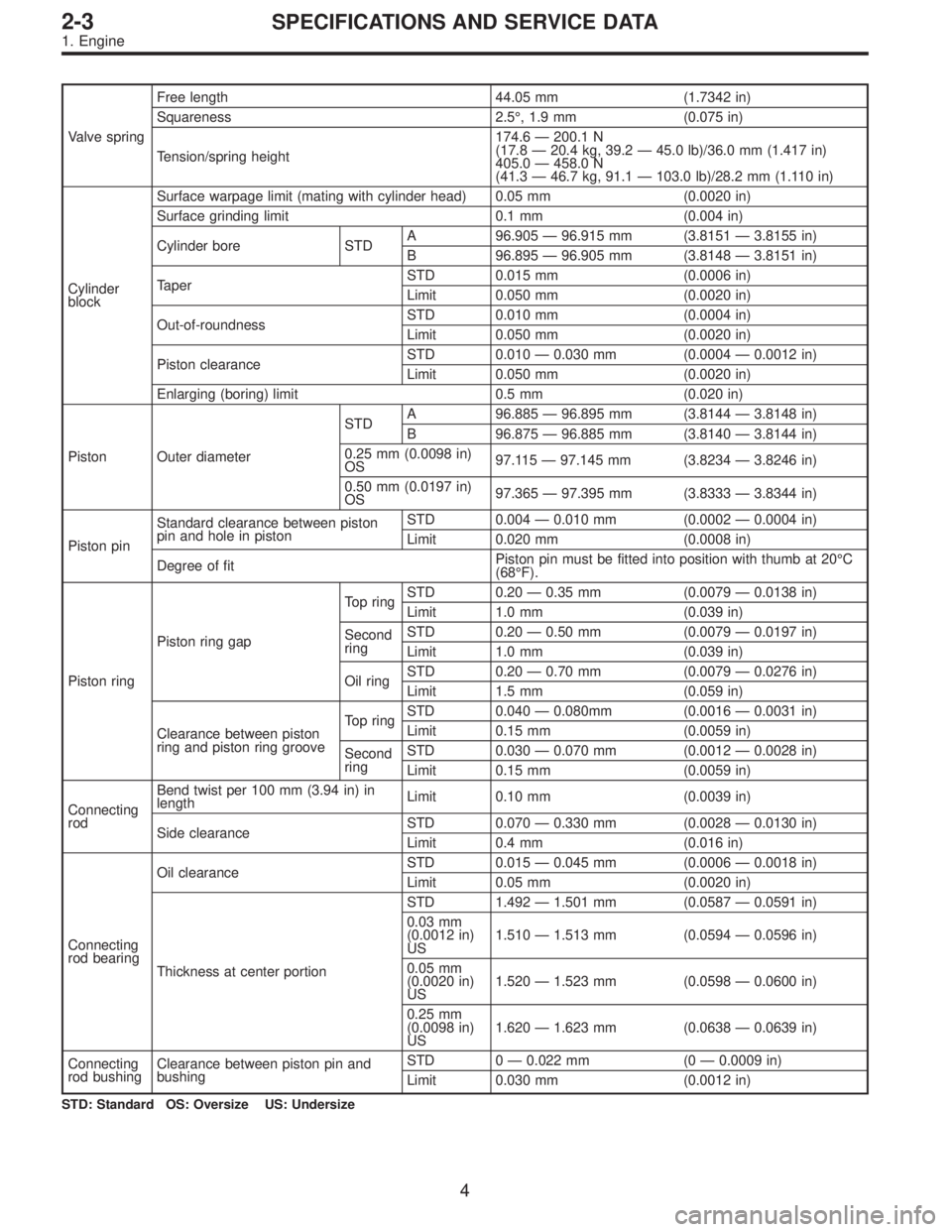
Valve springFree length 44.05 mm (1.7342 in)
Squareness 2.5°, 1.9 mm (0.075 in)
Tension/spring height174.6—200.1 N
(17.8—20.4 kg, 39.2—45.0 lb)/36.0 mm (1.417 in)
405.0—458.0 N
(41.3—46.7 kg, 91.1—103.0 lb)/28.2 mm (1.110 in)
Cylinder
blockSurface warpage limit (mating with cylinder head) 0.05 mm (0.0020 in)
Surface grinding limit 0.1 mm (0.004 in)
Cylinder bore STDA 96.905—96.915 mm (3.8151—3.8155 in)
B 96.895—96.905 mm (3.8148—3.8151 in)
TaperSTD 0.015 mm (0.0006 in)
Limit 0.050 mm (0.0020 in)
Out-of-roundnessSTD 0.010 mm (0.0004 in)
Limit 0.050 mm (0.0020 in)
Piston clearanceSTD 0.010—0.030 mm (0.0004—0.0012 in)
Limit 0.050 mm (0.0020 in)
Enlarging (boring) limit 0.5 mm (0.020 in)
Piston Outer diameterSTDA 96.885—96.895 mm (3.8144—3.8148 in)
B 96.875—96.885 mm (3.8140—3.8144 in)
0.25 mm (0.0098 in)
OS97.115—97.145 mm (3.8234—3.8246 in)
0.50 mm (0.0197 in)
OS97.365—97.395 mm (3.8333—3.8344 in)
Piston pinStandard clearance between piston
pin and hole in pistonSTD 0.004—0.010 mm (0.0002—0.0004 in)
Limit 0.020 mm (0.0008 in)
Degree of fitPiston pin must be fitted into position with thumb at 20°C
(68°F).
Piston ringPiston ring gapTop ringSTD 0.20—0.35 mm (0.0079—0.0138 in)
Limit 1.0 mm (0.039 in)
Second
ringSTD 0.20—0.50 mm (0.0079—0.0197 in)
Limit 1.0 mm (0.039 in)
Oil ringSTD 0.20—0.70 mm (0.0079—0.0276 in)
Limit 1.5 mm (0.059 in)
Clearance between piston
ring and piston ring grooveTop ringSTD 0.040—0.080mm (0.0016—0.0031 in)
Limit 0.15 mm (0.0059 in)
Second
ringSTD 0.030—0.070 mm (0.0012—0.0028 in)
Limit 0.15 mm (0.0059 in)
Connecting
rodBend twist per 100 mm (3.94 in) in
lengthLimit 0.10 mm (0.0039 in)
Side clearanceSTD 0.070—0.330 mm (0.0028—0.0130 in)
Limit 0.4 mm (0.016 in)
Connecting
rod bearingOil clearanceSTD 0.015—0.045 mm (0.0006—0.0018 in)
Limit 0.05 mm (0.0020 in)
Thickness at center portionSTD 1.492—1.501 mm (0.0587—0.0591 in)
0.03 mm
(0.0012 in)
US1.510—1.513 mm (0.0594—0.0596 in)
0.05 mm
(0.0020 in)
US1.520—1.523 mm (0.0598—0.0600 in)
0.25 mm
(0.0098 in)
US1.620—1.623 mm (0.0638—0.0639 in)
Connecting
rod bushingClearance between piston pin and
bushingSTD 0—0.022 mm (0—0.0009 in)
Limit 0.030 mm (0.0012 in)
STD: Standard OS: Oversize US: Undersize
4
2-3SPECIFICATIONS AND SERVICE DATA
1. Engine
Page 344 of 2890
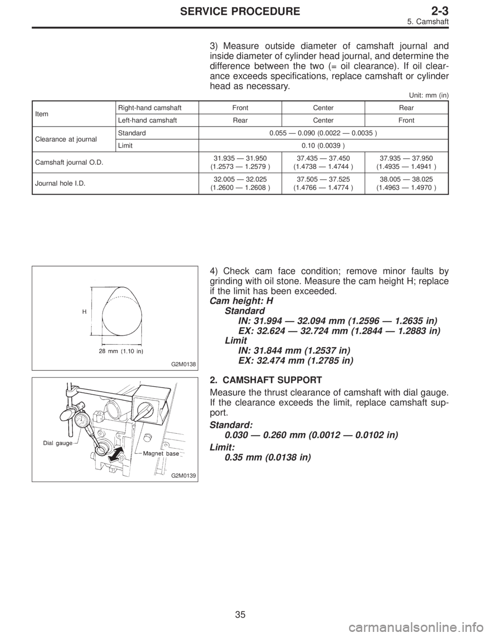
3) Measure outside diameter of camshaft journal and
inside diameter of cylinder head journal, and determine the
difference between the two (= oil clearance). If oil clear-
ance exceeds specifications, replace camshaft or cylinder
head as necessary.
Unit: mm (in)
ItemRight-hand camshaft Front Center Rear
Left-hand camshaft Rear Center Front
Clearance at journalStandard 0.055—0.090 (0.0022—0.0035 )
Limit 0.10 (0.0039 )
Camshaft journal O.D.31.935—31.950
(1.2573—1.2579 )37.435—37.450
(1.4738—1.4744 )37.935—37.950
(1.4935—1.4941 )
Journal hole I.D.32.005—32.025
(1.2600—1.2608 )37.505—37.525
(1.4766—1.4774 )38.005—38.025
(1.4963—1.4970 )
G2M0138
4) Check cam face condition; remove minor faults by
grinding with oil stone. Measure the cam height H; replace
if the limit has been exceeded.
Cam height: H
Standard
IN: 31.994—32.094 mm (1.2596—1.2635 in)
EX: 32.624—32.724 mm (1.2844—1.2883 in)
Limit
IN: 31.844 mm (1.2537 in)
EX: 32.474 mm (1.2785 in)
G2M0139
2. CAMSHAFT SUPPORT
Measure the thrust clearance of camshaft with dial gauge.
If the clearance exceeds the limit, replace camshaft sup-
port.
Standard:
0.030—0.260 mm (0.0012—0.0102 in)
Limit:
0.35 mm (0.0138 in)
35
2-3SERVICE PROCEDURE
5. Camshaft
Page 351 of 2890
C: INSPECTION
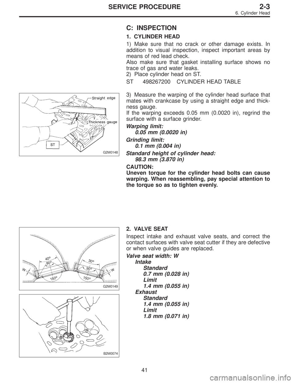
1. CYLINDER HEAD
1) Make sure that no crack or other damage exists. In
addition to visual inspection, inspect important areas by
means of red lead check.
Also make sure that gasket installing surface shows no
trace of gas and water leaks.
2) Place cylinder head on ST.
ST 498267200 CYLINDER HEAD TABLE
G2M0148
3) Measure the warping of the cylinder head surface that
mates with crankcase by using a straight edge and thick-
ness gauge.
If the warping exceeds 0.05 mm (0.0020 in), regrind the
surface with a surface grinder.
Warping limit:
0.05 mm (0.0020 in)
Grinding limit:
0.1 mm (0.004 in)
Standard height of cylinder head:
98.3 mm (3.870 in)
CAUTION:
Uneven torque for the cylinder head bolts can cause
warping. When reassembling, pay special attention to
the torque so as to tighten evenly.
G2M0149
B2M0074
2. VALVE SEAT
Inspect intake and exhaust valve seats, and correct the
contact surfaces with valve seat cutter if they are defective
or when valve guides are replaced.
Valve seat width: W
Intake
Standard
0.7 mm (0.028 in)
Limit
1.4 mm (0.055 in)
Exhaust
Standard
1.4 mm (0.055 in)
Limit
1.8 mm (0.071 in)
41
2-3SERVICE PROCEDURE
6. Cylinder Head
Page 354 of 2890
G2M0153
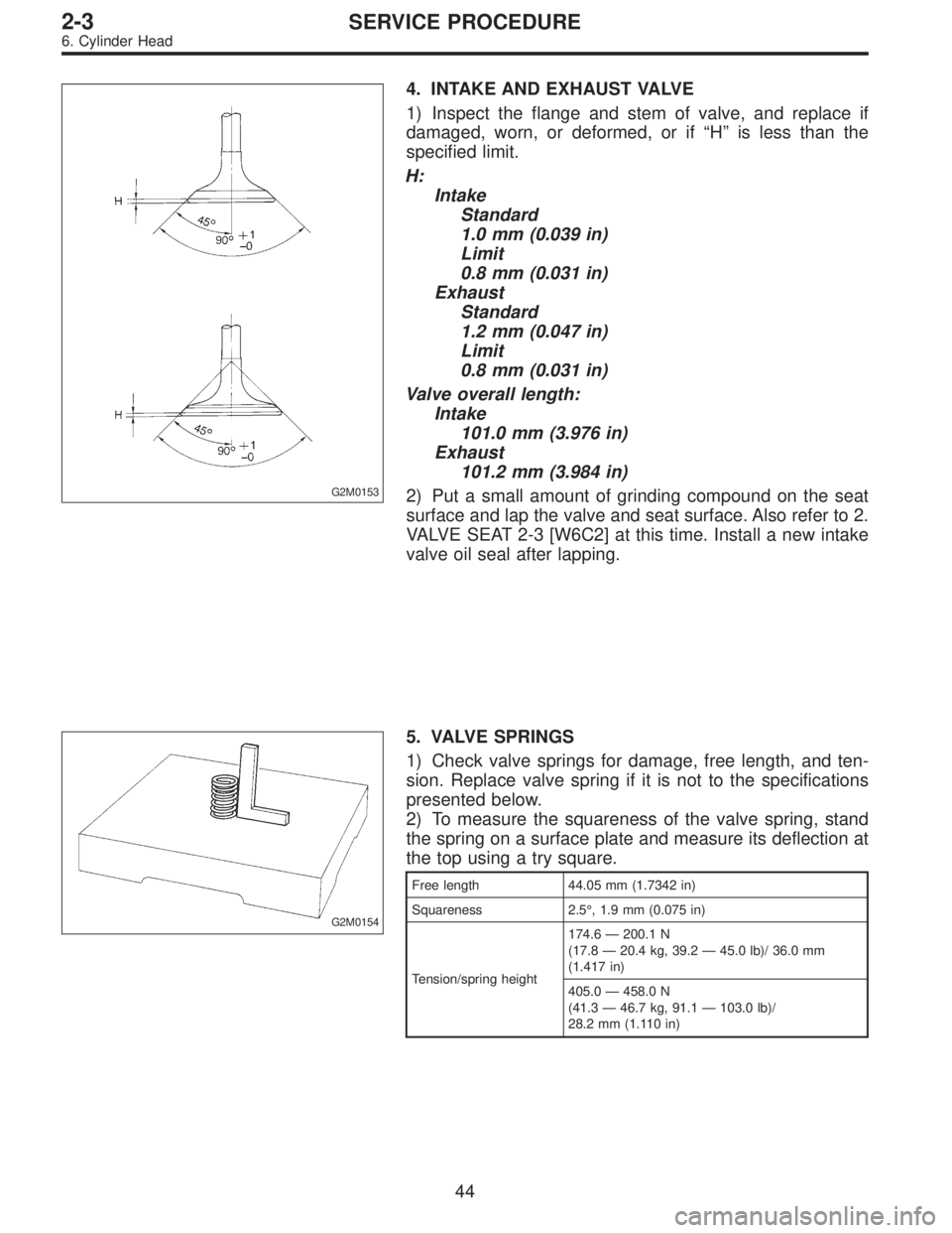
4. INTAKE AND EXHAUST VALVE
1) Inspect the flange and stem of valve, and replace if
damaged, worn, or deformed, or if“H”is less than the
specified limit.
H:
Intake
Standard
1.0 mm (0.039 in)
Limit
0.8 mm (0.031 in)
Exhaust
Standard
1.2 mm (0.047 in)
Limit
0.8 mm (0.031 in)
Valve overall length:
Intake
101.0 mm (3.976 in)
Exhaust
101.2 mm (3.984 in)
2) Put a small amount of grinding compound on the seat
surface and lap the valve and seat surface. Also refer to 2.
VALVE SEAT 2-3 [W6C2] at this time. Install a new intake
valve oil seal after lapping.
G2M0154
5. VALVE SPRINGS
1) Check valve springs for damage, free length, and ten-
sion. Replace valve spring if it is not to the specifications
presented below.
2) To measure the squareness of the valve spring, stand
the spring on a surface plate and measure its deflection at
the top using a try square.
Free length 44.05 mm (1.7342 in)
Squareness 2.5°, 1.9 mm (0.075 in)
Tension/spring height174.6—200.1 N
(17.8—20.4 kg, 39.2—45.0 lb)/ 36.0 mm
(1.417 in)
405.0—458.0 N
(41.3—46.7 kg, 91.1—103.0 lb)/
28.2 mm (1.110 in)
44
2-3SERVICE PROCEDURE
6. Cylinder Head
Page 366 of 2890
C: INSPECTION
1. CYLINDER BLOCK
1) Check for cracks and damage visually. Especially,
inspect important parts by means of red lead check.
2) Check the oil passages for clogging.
3) Inspect crankcase surface that mates with cylinder
head for warping by using a straight edge, and correct by
grinding if necessary.
Warping limit:
0.05 mm (0.0020 in)
Grinding limit:
0.1 mm (0.004 in)
Standard height of cylinder block:
201.0 mm (7.91 in)
B2M0082A
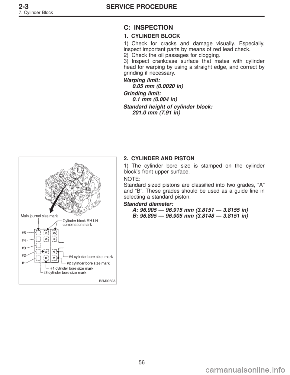
2. CYLINDER AND PISTON
1) The cylinder bore size is stamped on the cylinder
block’s front upper surface.
NOTE:
Standard sized pistons are classified into two grades,“A”
and“B”. These grades should be used as a guide line in
selecting a standard piston.
Standard diameter:
A: 96.905—96.915 mm (3.8151—3.8155 in)
B: 96.895—96.905 mm (3.8148—3.8151 in)
56
2-3SERVICE PROCEDURE
7. Cylinder Block
Page 367 of 2890
G2M0170
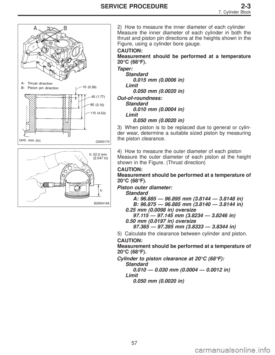
2) How to measure the inner diameter of each cylinder
Measure the inner diameter of each cylinder in both the
thrust and piston pin directions at the heights shown in the
Figure, using a cylinder bore gauge.
CAUTION:
Measurement should be performed at a temperature
20°C (68°F).
Taper:
Standard
0.015 mm (0.0006 in)
Limit
0.050 mm (0.0020 in)
Out-of-roundness:
Standard
0.010 mm (0.0004 in)
Limit
0.050 mm (0.0020 in)
3) When piston is to be replaced due to general or cylin-
der wear, determine a suitable sized piston by measuring
the piston clearance.
B2M0419A
4) How to measure the outer diameter of each piston
Measure the outer diameter of each piston at the height
shown in the Figure. (Thrust direction)
CAUTION:
Measurement should be performed at a temperature of
20°C (68°F).
Piston outer diameter:
Standard
A: 96.885—96.895 mm (3.8144—3.8148 in)
B: 96.875—96.885 mm (3.8140—3.8144 in)
0.25 mm (0.0098 in) oversize
97.115—97.145 mm (3.8234—3.8246 in)
0.50 mm (0.0197 in) oversize
97.365—97.395 mm (3.8333—3.8344 in)
5) Calculate the clearance between cylinder and piston.
CAUTION:
Measurement should be performed at a temperature of
20°C (68°F).
Cylinder to piston clearance at 20°C (68°F):
Standard
0.010—0.030 mm (0.0004—0.0012 in)
Limit
0.050 mm (0.0020 in)
57
2-3SERVICE PROCEDURE
7. Cylinder Block
Page 391 of 2890
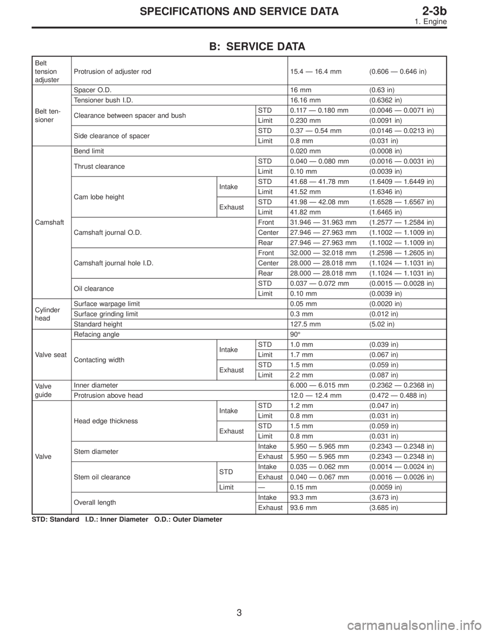
B: SERVICE DATA
Belt
tension
adjusterProtrusion of adjuster rod 15.4—16.4 mm (0.606—0.646 in)
Belt ten-
sionerSpacer O.D. 16 mm (0.63 in)
Tensioner bush I.D. 16.16 mm (0.6362 in)
Clearance between spacer and bushSTD 0.117—0.180 mm (0.0046—0.0071 in)
Limit 0.230 mm (0.0091 in)
Side clearance of spacerSTD 0.37—0.54 mm (0.0146—0.0213 in)
Limit 0.8 mm (0.031 in)
CamshaftBend limit 0.020 mm (0.0008 in)
Thrust clearanceSTD 0.040—0.080 mm (0.0016—0.0031 in)
Limit 0.10 mm (0.0039 in)
Cam lobe heightIntakeSTD 41.68—41.78 mm (1.6409—1.6449 in)
Limit 41.52 mm (1.6346 in)
ExhaustSTD 41.98—42.08 mm (1.6528—1.6567 in)
Limit 41.82 mm (1.6465 in)
Camshaft journal O.D.Front 31.946—31.963 mm (1.2577—1.2584 in)
Center 27.946—27.963 mm (1.1002—1.1009 in)
Rear 27.946—27.963 mm (1.1002—1.1009 in)
Camshaft journal hole I.D.Front 32.000—32.018 mm (1.2598—1.2605 in)
Center 28.000—28.018 mm (1.1024—1.1031 in)
Rear 28.000—28.018 mm (1.1024—1.1031 in)
Oil clearanceSTD 0.037—0.072 mm (0.0015—0.0028 in)
Limit 0.10 mm (0.0039 in)
Cylinder
headSurface warpage limit 0.05 mm (0.0020 in)
Surface grinding limit 0.3 mm (0.012 in)
Standard height 127.5 mm (5.02 in)
Valve seatRefacing angle 90°
Contacting widthIntakeSTD 1.0 mm (0.039 in)
Limit 1.7 mm (0.067 in)
ExhaustSTD 1.5 mm (0.059 in)
Limit 2.2 mm (0.087 in)
Valve
guideInner diameter 6.000—6.015 mm (0.2362—0.2368 in)
Protrusion above head 12.0—12.4 mm (0.472—0.488 in)
ValveHead edge thicknessIntakeSTD 1.2 mm (0.047 in)
Limit 0.8 mm (0.031 in)
ExhaustSTD 1.5 mm (0.059 in)
Limit 0.8 mm (0.031 in)
Stem diameterIntake 5.950—5.965 mm (0.2343—0.2348 in)
Exhaust 5.950—5.965 mm (0.2343—0.2348 in)
Stem oil clearanceSTDIntake 0.035—0.062 mm (0.0014—0.0024 in)
Exhaust 0.040—0.067 mm (0.0016—0.0026 in)
Limit—0.15 mm (0.0059 in)
Overall lengthIntake 93.3 mm (3.673 in)
Exhaust 93.6 mm (3.685 in)
STD: Standard I.D.: Inner Diameter O.D.: Outer Diameter
3
2-3bSPECIFICATIONS AND SERVICE DATA
1. Engine
Page 392 of 2890
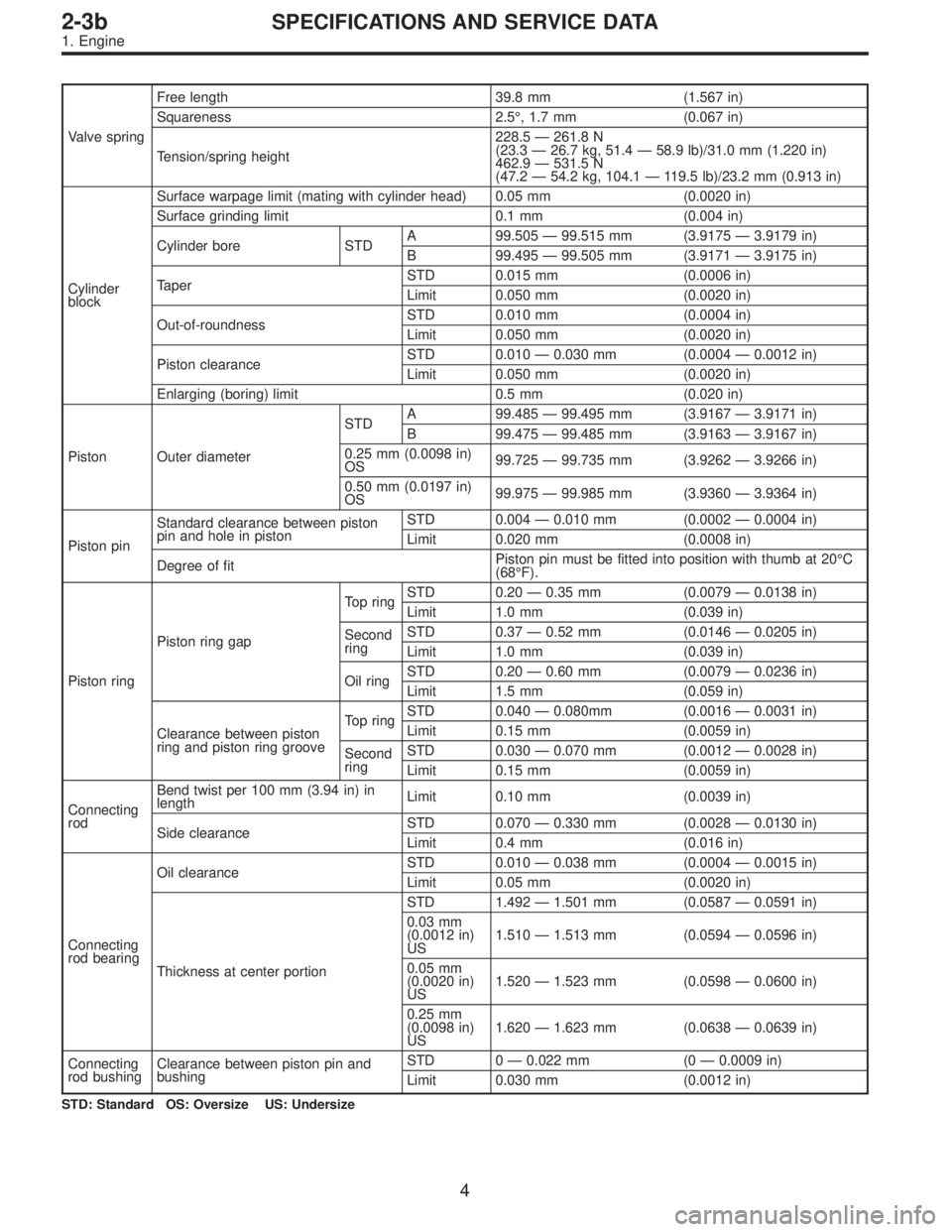
Valve springFree length 39.8 mm (1.567 in)
Squareness 2.5°, 1.7 mm (0.067 in)
Tension/spring height228.5—261.8 N
(23.3—26.7 kg, 51.4—58.9 lb)/31.0 mm (1.220 in)
462.9—531.5 N
(47.2—54.2 kg, 104.1—119.5 lb)/23.2 mm (0.913 in)
Cylinder
blockSurface warpage limit (mating with cylinder head) 0.05 mm (0.0020 in)
Surface grinding limit 0.1 mm (0.004 in)
Cylinder bore STDA 99.505—99.515 mm (3.9175—3.9179 in)
B 99.495—99.505 mm (3.9171—3.9175 in)
TaperSTD 0.015 mm (0.0006 in)
Limit 0.050 mm (0.0020 in)
Out-of-roundnessSTD 0.010 mm (0.0004 in)
Limit 0.050 mm (0.0020 in)
Piston clearanceSTD 0.010—0.030 mm (0.0004—0.0012 in)
Limit 0.050 mm (0.0020 in)
Enlarging (boring) limit 0.5 mm (0.020 in)
Piston Outer diameterSTDA 99.485—99.495 mm (3.9167—3.9171 in)
B 99.475—99.485 mm (3.9163—3.9167 in)
0.25 mm (0.0098 in)
OS99.725—99.735 mm (3.9262—3.9266 in)
0.50 mm (0.0197 in)
OS99.975—99.985 mm (3.9360—3.9364 in)
Piston pinStandard clearance between piston
pin and hole in pistonSTD 0.004—0.010 mm (0.0002—0.0004 in)
Limit 0.020 mm (0.0008 in)
Degree of fitPiston pin must be fitted into position with thumb at 20°C
(68°F).
Piston ringPiston ring gapTop ringSTD 0.20—0.35 mm (0.0079—0.0138 in)
Limit 1.0 mm (0.039 in)
Second
ringSTD 0.37—0.52 mm (0.0146—0.0205 in)
Limit 1.0 mm (0.039 in)
Oil ringSTD 0.20—0.60 mm (0.0079—0.0236 in)
Limit 1.5 mm (0.059 in)
Clearance between piston
ring and piston ring grooveTop ringSTD 0.040—0.080mm (0.0016—0.0031 in)
Limit 0.15 mm (0.0059 in)
Second
ringSTD 0.030—0.070 mm (0.0012—0.0028 in)
Limit 0.15 mm (0.0059 in)
Connecting
rodBend twist per 100 mm (3.94 in) in
lengthLimit 0.10 mm (0.0039 in)
Side clearanceSTD 0.070—0.330 mm (0.0028—0.0130 in)
Limit 0.4 mm (0.016 in)
Connecting
rod bearingOil clearanceSTD 0.010—0.038 mm (0.0004—0.0015 in)
Limit 0.05 mm (0.0020 in)
Thickness at center portionSTD 1.492—1.501 mm (0.0587—0.0591 in)
0.03 mm
(0.0012 in)
US1.510—1.513 mm (0.0594—0.0596 in)
0.05 mm
(0.0020 in)
US1.520—1.523 mm (0.0598—0.0600 in)
0.25 mm
(0.0098 in)
US1.620—1.623 mm (0.0638—0.0639 in)
Connecting
rod bushingClearance between piston pin and
bushingSTD 0—0.022 mm (0—0.0009 in)
Limit 0.030 mm (0.0012 in)
STD: Standard OS: Oversize US: Undersize
4
2-3bSPECIFICATIONS AND SERVICE DATA
1. Engine
Page 420 of 2890
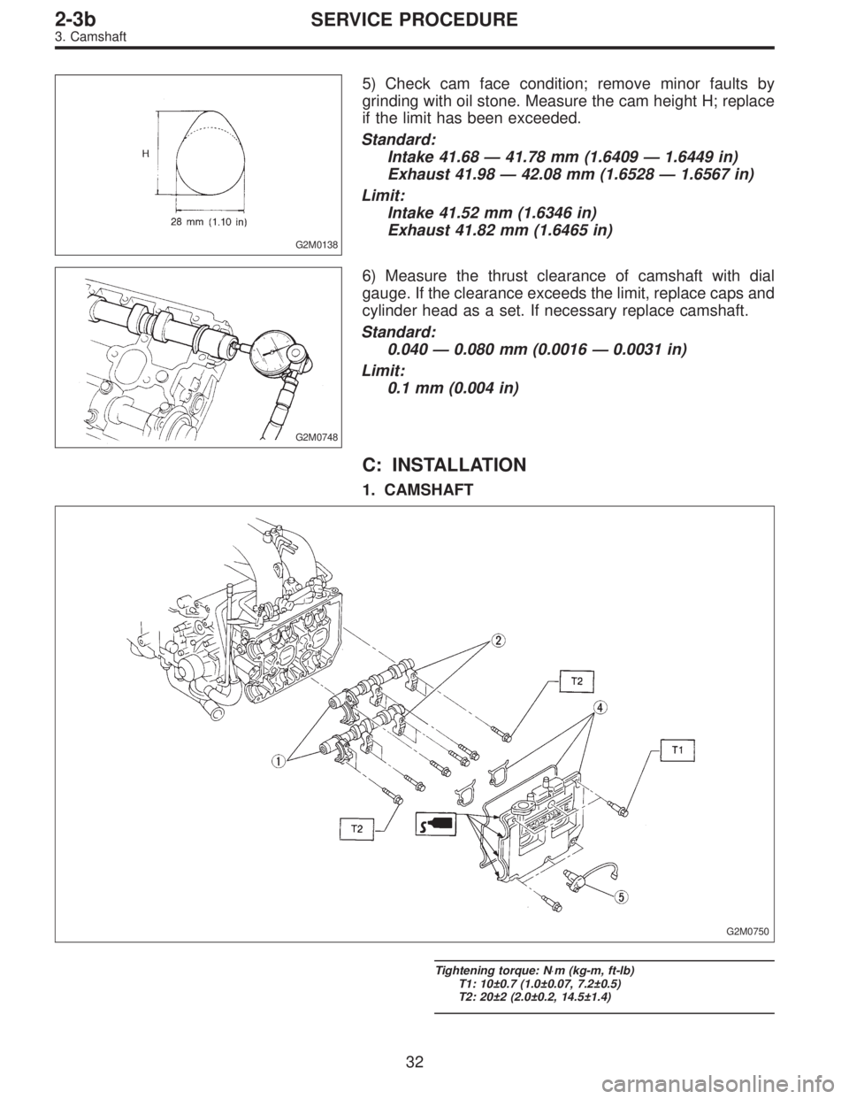
G2M0138
5) Check cam face condition; remove minor faults by
grinding with oil stone. Measure the cam height H; replace
if the limit has been exceeded.
Standard:
Intake 41.68—41.78 mm (1.6409—1.6449 in)
Exhaust 41.98—42.08 mm (1.6528—1.6567 in)
Limit:
Intake 41.52 mm (1.6346 in)
Exhaust 41.82 mm (1.6465 in)
G2M0748
6) Measure the thrust clearance of camshaft with dial
gauge. If the clearance exceeds the limit, replace caps and
cylinder head as a set. If necessary replace camshaft.
Standard:
0.040—0.080 mm (0.0016—0.0031 in)
Limit:
0.1 mm (0.004 in)
C: INSTALLATION
1. CAMSHAFT
G2M0750
Tightening torque: N⋅m (kg-m, ft-lb)
T1: 10±0.7 (1.0±0.07, 7.2±0.5)
T2: 20±2 (2.0±0.2, 14.5±1.4)
32
2-3bSERVICE PROCEDURE
3. Camshaft