length SUBARU LEGACY 1999 Service Repair Manual
[x] Cancel search | Manufacturer: SUBARU, Model Year: 1999, Model line: LEGACY, Model: SUBARU LEGACY 1999Pages: 1456, PDF Size: 59.93 MB
Page 56 of 1456
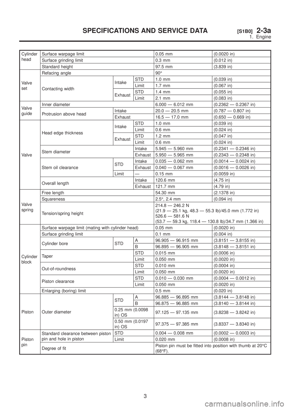
Cylinder
headSurface warpage limit 0.05 mm (0.0020 in)
Surface grinding limit 0.3 mm (0.012 in)
Standard height 97.5 mm (3.839 in)
Valve
setRefacing angle 90É
Contacting widthIntakeSTD 1.0 mm (0.039 in)
Limit 1.7 mm (0.067 in)
ExhaustSTD 1.4 mm (0.055 in)
Limit 2.1 mm (0.083 in)
Valve
guideInner diameter 6.000 Ð 6.012 mm (0.2362 Ð 0.2367 in)
Protrusion above headIntake 20.0 Ð 20.5 mm (0.787 Ð 0.807 in)
Exhaust 16.5 Ð 17.0 mm (0.650 Ð 0.669 in)
ValveHead edge thicknessIntakeSTD 1.0 mm (0.039 in)
Limit 0.6 mm (0.024 in)
ExhaustSTD 1.2 mm (0.047 in)
Limit 0.6 mm (0.024 in)
Stem diameterIntake 5.945 Ð 5.960 mm (0.2341 Ð 0.2346 in)
Exhaust 5.950 Ð 5.965 mm (0.2343 Ð 0.2348 in)
Stem oil clearanceSTDIntake 0.035 Ð 0.062 mm (0.0014 Ð 0.0024 in)
Exhaust 0.040 Ð 0.067 mm (0.0016 Ð 0.0026 in)
Limit Ð 0.15 mm (0.0059 in)
Overall lengthIntake 120.6 mm (4.75 in)
Exhaust 121.7 mm (4.79 in)
Valve
springFree length 54.30 mm (2.1378 in)
Squareness 2.5É, 2.4 mm (0.094 in)
Tension/spring height214.8 Ð 246.2 N
(21.9 Ð 25.1 kg, 48.3 Ð 55.3 lb)/45.0 mm (1.772 in)
526.6 Ð 581.6 N
(53.7 Ð 59.3 kg, 118.4 Ð 130.8 lb)/34.7 mm (1.366 in)
Cylinder
blockSurface warpage limit (mating with cylinder head) 0.05 mm (0.0020 in)
Surface grinding limit 0.1 mm (0.004 in)
Cylinder bore STDA 96.905 Ð 96.915 mm (3.8151 Ð 3.8155 in)
B 96.895 Ð 96.905 mm (3.8148 Ð 3.8151 in)
TaperSTD 0.015 mm (0.0006 in)
Limit 0.050 mm (0.0020 in)
Out-of-roundnessSTD 0.010 mm (0.0004 in)
Limit 0.050 mm (0.0020 in)
Piston clearanceSTD 0.010 Ð 0.030 mm (0.0004 Ð 0.0012 in)
Limit 0.050 mm (0.0020 in)
Enlarging (boring) limit 0.5 mm (0.020 in)
Piston Outer diameterSTDA 96.885 Ð 96.895 mm (3.8144 Ð 3.8148 in)
B 96.875 Ð 96.885 mm (3.8140 Ð 3.8144 in)
0.25 mm (0.0098
in) OS97.125 Ð 97.135 mm (3.8238 Ð 3.8242 in)
0.50 mm (0.0197
in) OS97.375 Ð 97.385 mm (3.8337 Ð 3.8340 in)
Piston
pinStandard clearance between piston
pin and hole in pistonSTD 0.004 Ð 0.008 mm (0.0002 Ð 0.0003 in)
Limit 0.020 mm (0.0008 in)
Degree of fitPiston pin must be fitted into position with thumb at 20ÉC
(68ÉF).
3
[S1B0]2-3aSPECIFICATIONS AND SERVICE DATA
1. Engine
Page 57 of 1456
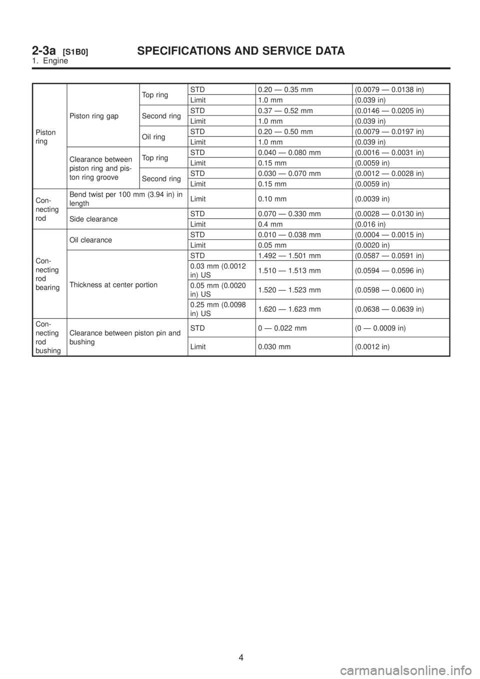
Piston
ringPiston ring gapTop ringSTD 0.20 Ð 0.35 mm (0.0079 Ð 0.0138 in)
Limit 1.0 mm (0.039 in)
Second ringSTD 0.37 Ð 0.52 mm (0.0146 Ð 0.0205 in)
Limit 1.0 mm (0.039 in)
Oil ringSTD 0.20 Ð 0.50 mm (0.0079 Ð 0.0197 in)
Limit 1.0 mm (0.039 in)
Clearance between
piston ring and pis-
ton ring grooveTop ringSTD 0.040 Ð 0.080 mm (0.0016 Ð 0.0031 in)
Limit 0.15 mm (0.0059 in)
Second ringSTD 0.030 Ð 0.070 mm (0.0012 Ð 0.0028 in)
Limit 0.15 mm (0.0059 in)
Con-
necting
rodBend twist per 100 mm (3.94 in) in
lengthLimit 0.10 mm (0.0039 in)
Side clearanceSTD 0.070 Ð 0.330 mm (0.0028 Ð 0.0130 in)
Limit 0.4 mm (0.016 in)
Con-
necting
rod
bearingOil clearanceSTD 0.010 Ð 0.038 mm (0.0004 Ð 0.0015 in)
Limit 0.05 mm (0.0020 in)
Thickness at center portionSTD 1.492 Ð 1.501 mm (0.0587 Ð 0.0591 in)
0.03 mm (0.0012
in) US1.510 Ð 1.513 mm (0.0594 Ð 0.0596 in)
0.05 mm (0.0020
in) US1.520 Ð 1.523 mm (0.0598 Ð 0.0600 in)
0.25 mm (0.0098
in) US1.620 Ð 1.623 mm (0.0638 Ð 0.0639 in)
Con-
necting
rod
bushingClearance between piston pin and
bushingSTD 0 Ð 0.022 mm (0 Ð 0.0009 in)
Limit 0.030 mm (0.0012 in)
4
2-3a[S1B0]SPECIFICATIONS AND SERVICE DATA
1. Engine
Page 68 of 1456
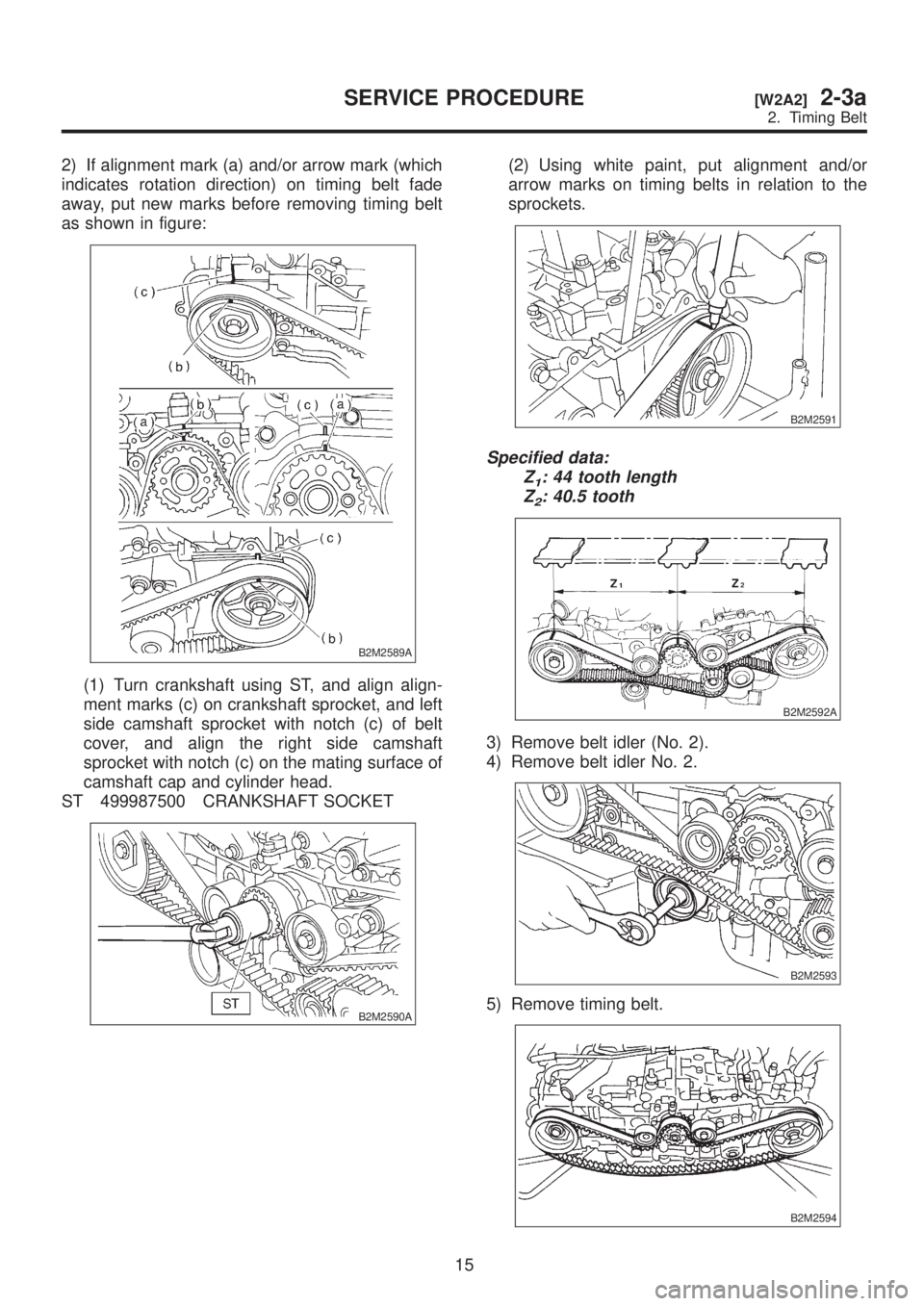
2) If alignment mark (a) and/or arrow mark (which
indicates rotation direction) on timing belt fade
away, put new marks before removing timing belt
as shown in figure:
B2M2589A
(1) Turn crankshaft using ST, and align align-
ment marks (c) on crankshaft sprocket, and left
side camshaft sprocket with notch (c) of belt
cover, and align the right side camshaft
sprocket with notch (c) on the mating surface of
camshaft cap and cylinder head.
ST 499987500 CRANKSHAFT SOCKET
B2M2590A
(2) Using white paint, put alignment and/or
arrow marks on timing belts in relation to the
sprockets.
B2M2591
Specified data:
Z
1: 44 tooth length
Z
2: 40.5 tooth
B2M2592A
3) Remove belt idler (No. 2).
4) Remove belt idler No. 2.
B2M2593
5) Remove timing belt.
B2M2594
15
[W2A2]2-3aSERVICE PROCEDURE
2. Timing Belt
Page 100 of 1456
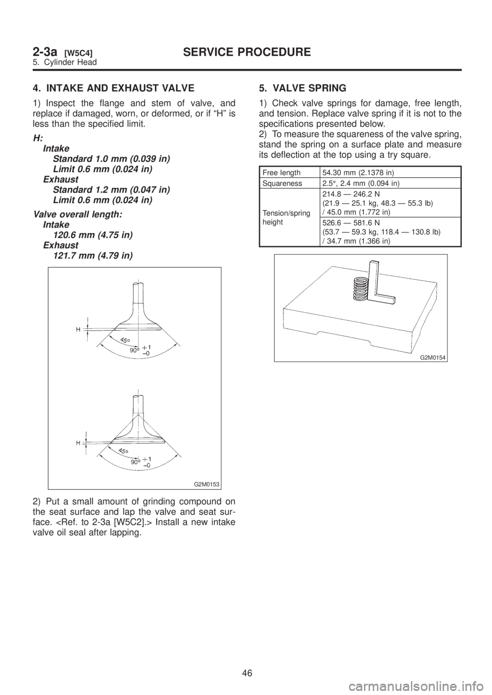
4. INTAKE AND EXHAUST VALVE
1) Inspect the flange and stem of valve, and
replace if damaged, worn, or deformed, or if ªHº is
less than the specified limit.
H:
Intake
Standard 1.0 mm (0.039 in)
Limit 0.6 mm (0.024 in)
Exhaust
Standard 1.2 mm (0.047 in)
Limit 0.6 mm (0.024 in)
Valve overall length:
Intake
120.6 mm (4.75 in)
Exhaust
121.7 mm (4.79 in)
G2M0153
2) Put a small amount of grinding compound on
the seat surface and lap the valve and seat sur-
face.
valve oil seal after lapping.
5. VALVE SPRING
1) Check valve springs for damage, free length,
and tension. Replace valve spring if it is not to the
specifications presented below.
2) To measure the squareness of the valve spring,
stand the spring on a surface plate and measure
its deflection at the top using a try square.
Free length 54.30 mm (2.1378 in)
Squareness 2.5É, 2.4 mm (0.094 in)
Tension/spring
height214.8 Ð 246.2 N
(21.9 Ð 25.1 kg, 48.3 Ð 55.3 lb)
/ 45.0 mm (1.772 in)
526.6 Ð 581.6 N
(53.7 Ð 59.3 kg, 118.4 Ð 130.8 lb)
/ 34.7 mm (1.366 in)
G2M0154
46
2-3a[W5C4]SERVICE PROCEDURE
5. Cylinder Head
Page 114 of 1456
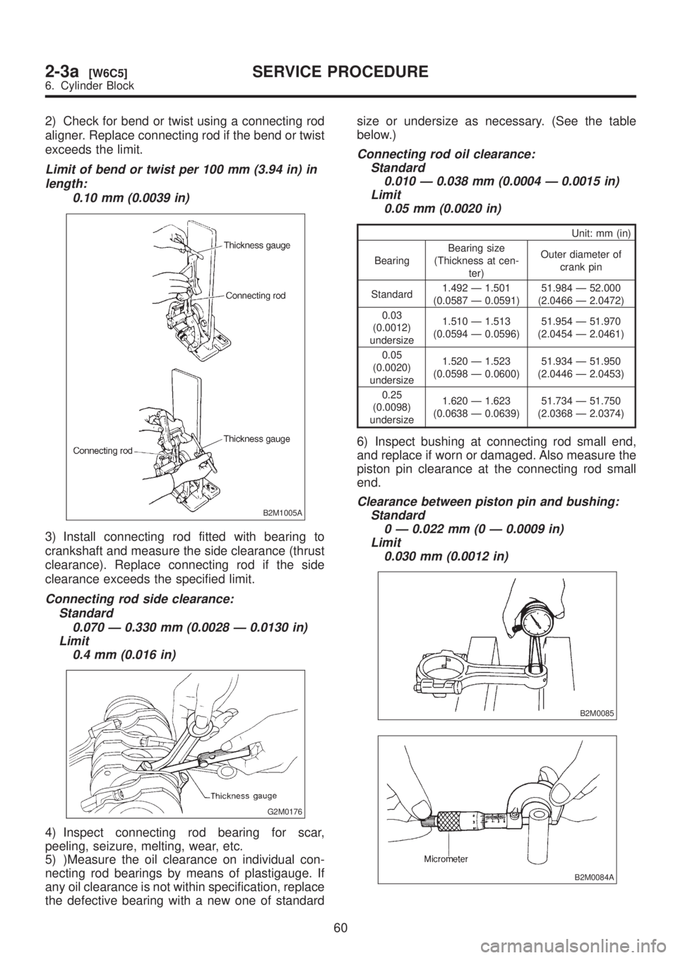
2) Check for bend or twist using a connecting rod
aligner. Replace connecting rod if the bend or twist
exceeds the limit.
Limit of bend or twist per 100 mm (3.94 in) in
length:
0.10 mm (0.0039 in)
B2M1005A
3) Install connecting rod fitted with bearing to
crankshaft and measure the side clearance (thrust
clearance). Replace connecting rod if the side
clearance exceeds the specified limit.
Connecting rod side clearance:
Standard
0.070 Ð 0.330 mm (0.0028 Ð 0.0130 in)
Limit
0.4 mm (0.016 in)
G2M0176
4) Inspect connecting rod bearing for scar,
peeling, seizure, melting, wear, etc.
5) )Measure the oil clearance on individual con-
necting rod bearings by means of plastigauge. If
any oil clearance is not within specification, replace
the defective bearing with a new one of standardsize or undersize as necessary. (See the table
below.)
Connecting rod oil clearance:
Standard
0.010 Ð 0.038 mm (0.0004 Ð 0.0015 in)
Limit
0.05 mm (0.0020 in)
Unit: mm (in)
BearingBearing size
(Thickness at cen-
ter)Outer diameter of
crank pin
Standard1.492 Ð 1.501
(0.0587 Ð 0.0591)51.984 Ð 52.000
(2.0466 Ð 2.0472)
0.03
(0.0012)
undersize1.510 Ð 1.513
(0.0594 Ð 0.0596)51.954 Ð 51.970
(2.0454 Ð 2.0461)
0.05
(0.0020)
undersize1.520 Ð 1.523
(0.0598 Ð 0.0600)51.934 Ð 51.950
(2.0446 Ð 2.0453)
0.25
(0.0098)
undersize1.620 Ð 1.623
(0.0638 Ð 0.0639)51.734 Ð 51.750
(2.0368 Ð 2.0374)
6) Inspect bushing at connecting rod small end,
and replace if worn or damaged. Also measure the
piston pin clearance at the connecting rod small
end.
Clearance between piston pin and bushing:
Standard
0 Ð 0.022 mm (0 Ð 0.0009 in)
Limit
0.030 mm (0.0012 in)
B2M0085
B2M0084A
60
2-3a[W6C5]SERVICE PROCEDURE
6. Cylinder Block
Page 134 of 1456
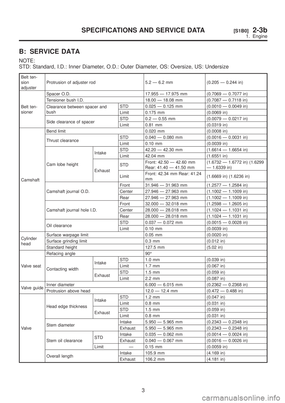
B: SERVICE DATA
NOTE:
STD: Standard, I.D.: Inner Diameter, O.D.: Outer Diameter, OS: Oversize, US: Undersize
Belt ten-
sion
adjusterProtrusion of adjuster rod 5.2 Ð 6.2 mm (0.205 Ð 0.244 in)
Belt ten-
sionerSpacer O.D. 17.955 Ð 17.975 mm (0.7069 Ð 0.7077 in)
Tensioner bush I.D. 18.00 Ð 18.08 mm (0.7087 Ð 0.7118 in)
Clearance between spacer and
bushSTD 0.025 Ð 0.125 mm (0.0010 Ð 0.0049 in)
Limit 0.175 mm (0.0069 in)
Side clearance of spacerSTD 0.2 Ð 0.55 mm (0.0079 Ð 0.0217 in)
Limit 0.81 mm (0.0319 in)
CamshaftBend limit 0.020 mm (0.0008 in)
Thrust clearanceSTD 0.040 Ð 0.080 mm (0.0016 Ð 0.0031 in)
Limit 0.10 mm (0.0039 in)
Cam lobe heightIntakeSTD 42.20 Ð 42.30 mm (1.6614 Ð 1.6654 in)
Limit 42.04 mm (1.6551 in)
ExhaustSTDFront: 42.50 Ð 42.60 mm
Rear: 41.40 Ð 41.50 mm(1.6732 Ð 1.6772 in) (1.6299
Ð 1.6339 in)
LimitFront: 42.34 mm Rear: 41.24
mm(1.6669 in) (1.6236 in)
Camshaft journal O.D.Front 31.946 Ð 31.963 mm (1.2577 Ð 1.2584 in)
Center 27.946 Ð 27.963 mm (1.1002 Ð 1.1009 in)
Rear 27.946 Ð 27.963 mm (1.1002 Ð 1.1009 in)
Camshaft journal hole I.D.Front 32.000 Ð 32.018 mm (1.2598 Ð 1.2605 in)
Center 28.000 Ð 28.018 mm (1.1024 Ð 1.1031 in)
Rear 28.000 Ð 28.018 mm (1.1024 Ð 1.1031 in)
Oil clearanceSTD 0.037 Ð 0.072 mm (0.0015 Ð 0.0028 in)
Limit 0.10 mm (0.0039 in)
Cylinder
headSurface warpage limit 0.05 mm (0.0020 in)
Surface grinding limit 0.3 mm (0.012 in)
Standard height 127.5 mm (5.02 in)
Valve seatRefacing angle 90É
Contacting widthIntakeSTD 1.0 mm (0.039 in)
Limit 1.7 mm (0.067 in)
ExhaustSTD 1.5 mm (0.059 in)
Limit 2.2 mm (0.087 in)
Valve guideInner diameter 6.000 Ð 6.015 mm (0.2362 Ð 0.2368 in)
Protrusion above head 12.0 Ð 12.4 mm (0.472 Ð 0.488 in)
ValveHead edge thicknessIntakeSTD 1.2 mm (0.047 in)
Limit 0.8 mm (0.031 in)
ExhaustSTD 1.5 mm (0.059 in)
Limit 0.8 mm (0.031 in)
Stem diameterIntake 5.950 Ð 5.965 mm (0.2343 Ð 0.2348 in)
Exhaust 5.950 Ð 5.965 mm (0.2343 Ð 0.2348 in)
Stem oil clearanceSTDIntake 0.035 Ð 0.062 mm (0.0014 Ð 0.0024 in)
Exhaust 0.040 Ð 0.067 mm (0.0016 Ð 0.0026 in)
Limit Ð 0.15 mm (0.0059 in)
Overall lengthIntake 105.9 mm (4.169 in)
Exhaust 106.2 mm (4.181 in)
3
[S1B0]2-3bSPECIFICATIONS AND SERVICE DATA
1. Engine
Page 135 of 1456
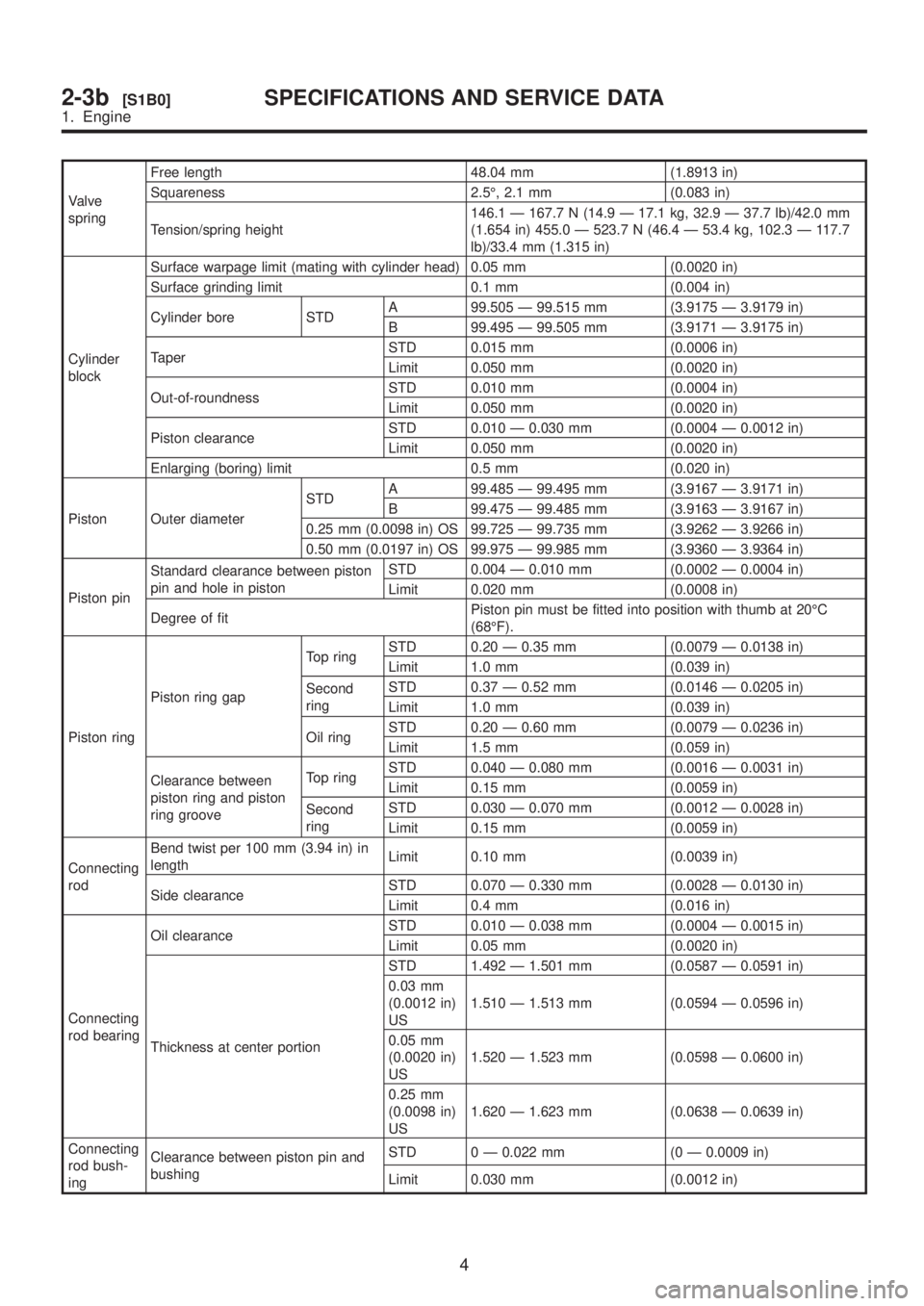
Valve
springFree length 48.04 mm (1.8913 in)
Squareness 2.5É, 2.1 mm (0.083 in)
Tension/spring height146.1 Ð 167.7 N (14.9 Ð 17.1 kg, 32.9 Ð 37.7 lb)/42.0 mm
(1.654 in) 455.0 Ð 523.7 N (46.4 Ð 53.4 kg, 102.3 Ð 117.7
lb)/33.4 mm (1.315 in)
Cylinder
blockSurface warpage limit (mating with cylinder head) 0.05 mm (0.0020 in)
Surface grinding limit 0.1 mm (0.004 in)
Cylinder bore STDA 99.505 Ð 99.515 mm (3.9175 Ð 3.9179 in)
B 99.495 Ð 99.505 mm (3.9171 Ð 3.9175 in)
TaperSTD 0.015 mm (0.0006 in)
Limit 0.050 mm (0.0020 in)
Out-of-roundnessSTD 0.010 mm (0.0004 in)
Limit 0.050 mm (0.0020 in)
Piston clearanceSTD 0.010 Ð 0.030 mm (0.0004 Ð 0.0012 in)
Limit 0.050 mm (0.0020 in)
Enlarging (boring) limit 0.5 mm (0.020 in)
Piston Outer diameterSTDA 99.485 Ð 99.495 mm (3.9167 Ð 3.9171 in)
B 99.475 Ð 99.485 mm (3.9163 Ð 3.9167 in)
0.25 mm (0.0098 in) OS 99.725 Ð 99.735 mm (3.9262 Ð 3.9266 in)
0.50 mm (0.0197 in) OS 99.975 Ð 99.985 mm (3.9360 Ð 3.9364 in)
Piston pinStandard clearance between piston
pin and hole in pistonSTD 0.004 Ð 0.010 mm (0.0002 Ð 0.0004 in)
Limit 0.020 mm (0.0008 in)
Degree of fitPiston pin must be fitted into position with thumb at 20ÉC
(68ÉF).
Piston ringPiston ring gapTop ringSTD 0.20 Ð 0.35 mm (0.0079 Ð 0.0138 in)
Limit 1.0 mm (0.039 in)
Second
ringSTD 0.37 Ð 0.52 mm (0.0146 Ð 0.0205 in)
Limit 1.0 mm (0.039 in)
Oil ringSTD 0.20 Ð 0.60 mm (0.0079 Ð 0.0236 in)
Limit 1.5 mm (0.059 in)
Clearance between
piston ring and piston
ring grooveTop ringSTD 0.040 Ð 0.080 mm (0.0016 Ð 0.0031 in)
Limit 0.15 mm (0.0059 in)
Second
ringSTD 0.030 Ð 0.070 mm (0.0012 Ð 0.0028 in)
Limit 0.15 mm (0.0059 in)
Connecting
rodBend twist per 100 mm (3.94 in) in
lengthLimit 0.10 mm (0.0039 in)
Side clearanceSTD 0.070 Ð 0.330 mm (0.0028 Ð 0.0130 in)
Limit 0.4 mm (0.016 in)
Connecting
rod bearingOil clearanceSTD 0.010 Ð 0.038 mm (0.0004 Ð 0.0015 in)
Limit 0.05 mm (0.0020 in)
Thickness at center portionSTD 1.492 Ð 1.501 mm (0.0587 Ð 0.0591 in)
0.03 mm
(0.0012 in)
US1.510 Ð 1.513 mm (0.0594 Ð 0.0596 in)
0.05 mm
(0.0020 in)
US1.520 Ð 1.523 mm (0.0598 Ð 0.0600 in)
0.25 mm
(0.0098 in)
US1.620 Ð 1.623 mm (0.0638 Ð 0.0639 in)
Connecting
rod bush-
ingClearance between piston pin and
bushingSTD 0 Ð 0.022 mm (0 Ð 0.0009 in)
Limit 0.030 mm (0.0012 in)
4
2-3b[S1B0]SPECIFICATIONS AND SERVICE DATA
1. Engine
Page 147 of 1456
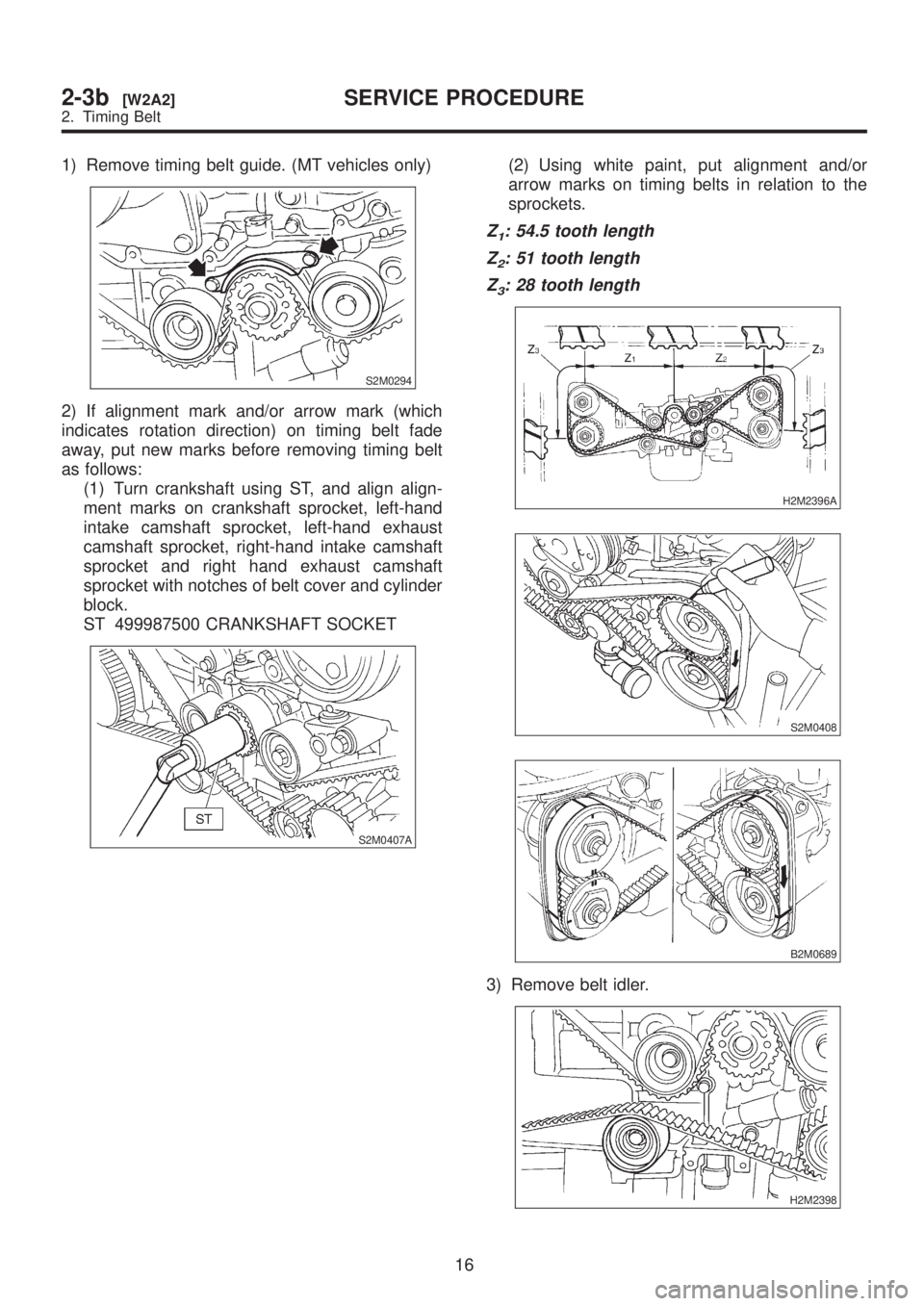
1) Remove timing belt guide. (MT vehicles only)
S2M0294
2) If alignment mark and/or arrow mark (which
indicates rotation direction) on timing belt fade
away, put new marks before removing timing belt
as follows:
(1) Turn crankshaft using ST, and align align-
ment marks on crankshaft sprocket, left-hand
intake camshaft sprocket, left-hand exhaust
camshaft sprocket, right-hand intake camshaft
sprocket and right hand exhaust camshaft
sprocket with notches of belt cover and cylinder
block.
ST 499987500 CRANKSHAFT SOCKET
S2M0407A
(2) Using white paint, put alignment and/or
arrow marks on timing belts in relation to the
sprockets.
Z1: 54.5 tooth length
Z
2: 51 tooth length
Z
3: 28 tooth length
H2M2396A
S2M0408
B2M0689
3) Remove belt idler.
H2M2398
16
2-3b[W2A2]SERVICE PROCEDURE
2. Timing Belt
Page 171 of 1456
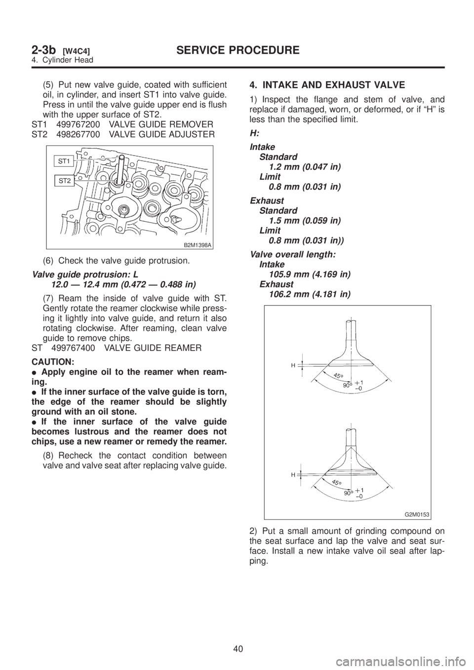
(5) Put new valve guide, coated with sufficient
oil, in cylinder, and insert ST1 into valve guide.
Press in until the valve guide upper end is flush
with the upper surface of ST2.
ST1 499767200 VALVE GUIDE REMOVER
ST2 498267700 VALVE GUIDE ADJUSTER
B2M1398A
(6) Check the valve guide protrusion.
Valve guide protrusion: L
12.0 Ð 12.4 mm (0.472 Ð 0.488 in)
(7) Ream the inside of valve guide with ST.
Gently rotate the reamer clockwise while press-
ing it lightly into valve guide, and return it also
rotating clockwise. After reaming, clean valve
guide to remove chips.
ST 499767400 VALVE GUIDE REAMER
CAUTION:
IApply engine oil to the reamer when ream-
ing.
IIf the inner surface of the valve guide is torn,
the edge of the reamer should be slightly
ground with an oil stone.
IIf the inner surface of the valve guide
becomes lustrous and the reamer does not
chips, use a new reamer or remedy the reamer.
(8) Recheck the contact condition between
valve and valve seat after replacing valve guide.
4. INTAKE AND EXHAUST VALVE
1) Inspect the flange and stem of valve, and
replace if damaged, worn, or deformed, or if ªHº is
less than the specified limit.
H:
Intake
Standard
1.2 mm (0.047 in)
Limit
0.8 mm (0.031 in)
Exhaust
Standard
1.5 mm (0.059 in)
Limit
0.8 mm (0.031 in))
Valve overall length:
Intake
105.9 mm (4.169 in)
Exhaust
106.2 mm (4.181 in)
G2M0153
2) Put a small amount of grinding compound on
the seat surface and lap the valve and seat sur-
face. Install a new intake valve oil seal after lap-
ping.
40
2-3b[W4C4]SERVICE PROCEDURE
4. Cylinder Head
Page 172 of 1456
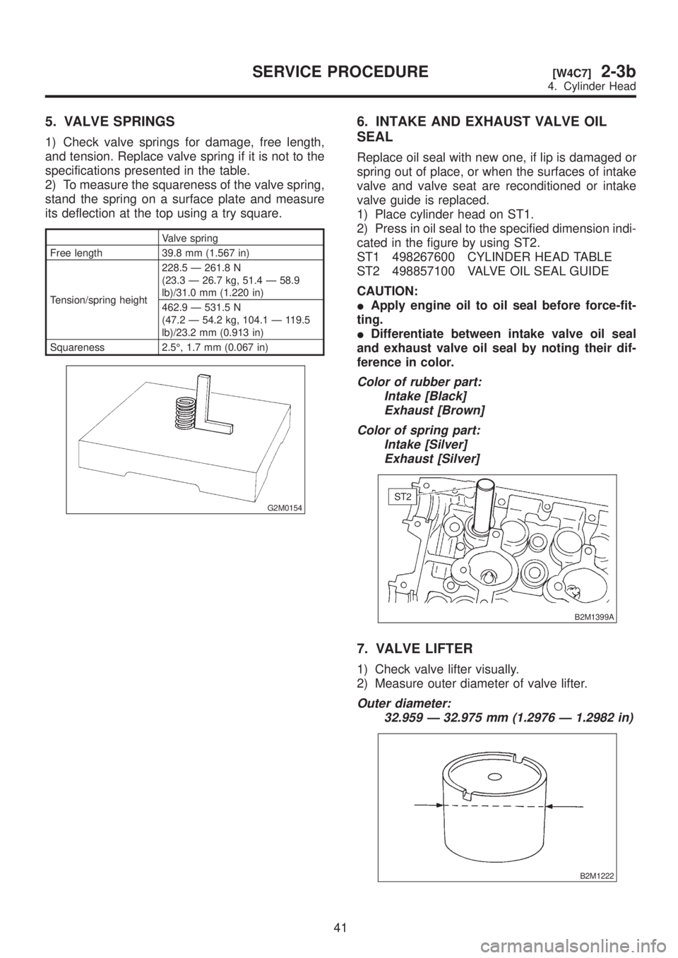
5. VALVE SPRINGS
1) Check valve springs for damage, free length,
and tension. Replace valve spring if it is not to the
specifications presented in the table.
2) To measure the squareness of the valve spring,
stand the spring on a surface plate and measure
its deflection at the top using a try square.
Valve spring
Free length 39.8 mm (1.567 in)
Tension/spring height228.5 Ð 261.8 N
(23.3 Ð 26.7 kg, 51.4 Ð 58.9
lb)/31.0 mm (1.220 in)
462.9 Ð 531.5 N
(47.2 Ð 54.2 kg, 104.1 Ð 119.5
lb)/23.2 mm (0.913 in)
Squareness 2.5É, 1.7 mm (0.067 in)
G2M0154
6. INTAKE AND EXHAUST VALVE OIL
SEAL
Replace oil seal with new one, if lip is damaged or
spring out of place, or when the surfaces of intake
valve and valve seat are reconditioned or intake
valve guide is replaced.
1) Place cylinder head on ST1.
2) Press in oil seal to the specified dimension indi-
cated in the figure by using ST2.
ST1 498267600 CYLINDER HEAD TABLE
ST2 498857100 VALVE OIL SEAL GUIDE
CAUTION:
IApply engine oil to oil seal before force-fit-
ting.
IDifferentiate between intake valve oil seal
and exhaust valve oil seal by noting their dif-
ference in color.
Color of rubber part:
Intake [Black]
Exhaust [Brown]
Color of spring part:
Intake [Silver]
Exhaust [Silver]
B2M1399A
7. VALVE LIFTER
1) Check valve lifter visually.
2) Measure outer diameter of valve lifter.
Outer diameter:
32.959 Ð 32.975 mm (1.2976 Ð 1.2982 in)
B2M1222
41
[W4C7]2-3bSERVICE PROCEDURE
4. Cylinder Head