clutch SUBARU LEGACY 1999 Service Repair Manual
[x] Cancel search | Manufacturer: SUBARU, Model Year: 1999, Model line: LEGACY, Model: SUBARU LEGACY 1999Pages: 1456, PDF Size: 59.93 MB
Page 1185 of 1456
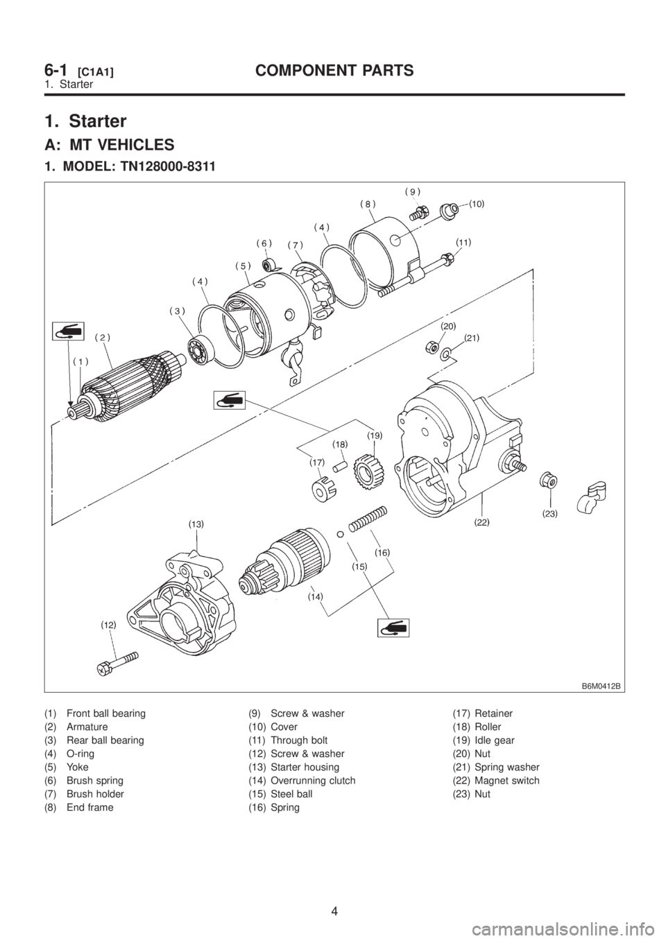
1. Starter
A: MT VEHICLES
1. MODEL: TN128000-8311
B6M0412B
(1) Front ball bearing
(2) Armature
(3) Rear ball bearing
(4) O-ring
(5) Yoke
(6) Brush spring
(7) Brush holder
(8) End frame(9) Screw & washer
(10) Cover
(11) Through bolt
(12) Screw & washer
(13) Starter housing
(14) Overrunning clutch
(15) Steel ball
(16) Spring(17) Retainer
(18) Roller
(19) Idle gear
(20) Nut
(21) Spring washer
(22) Magnet switch
(23) Nut
4
6-1[C1A1]COMPONENT PARTS
1. Starter
Page 1186 of 1456
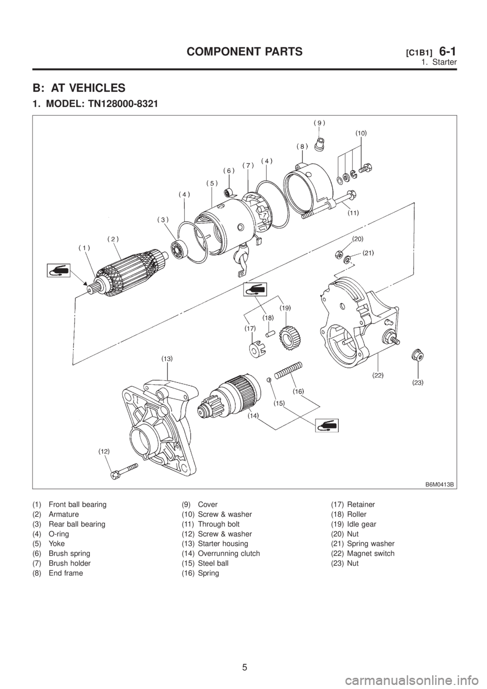
B: AT VEHICLES
1. MODEL: TN128000-8321
B6M0413B
(1) Front ball bearing
(2) Armature
(3) Rear ball bearing
(4) O-ring
(5) Yoke
(6) Brush spring
(7) Brush holder
(8) End frame(9) Cover
(10) Screw & washer
(11) Through bolt
(12) Screw & washer
(13) Starter housing
(14) Overrunning clutch
(15) Steel ball
(16) Spring(17) Retainer
(18) Roller
(19) Idle gear
(20) Nut
(21) Spring washer
(22) Magnet switch
(23) Nut
5
[C1B1]6-1COMPONENT PARTS
1. Starter
Page 1190 of 1456
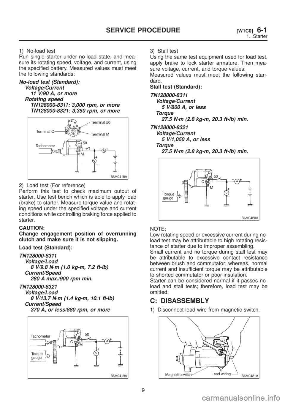
1) No-load test
Run single starter under no-load state, and mea-
sure its rotating speed, voltage, and current, using
the specified battery. Measured values must meet
the following standards:
No-load test (Standard):
Voltage/Current
11 V/90 A, or more
Rotating speed
TN128000-8311: 3,000 rpm, or more
TN128000-8321: 3,350 rpm, or more
B6M0418A
2) Load test (For reference)
Perform this test to check maximum output of
starter. Use test bench which is able to apply load
(brake) to starter. Measure torque value and rotat-
ing speed under the specified voltage and current
conditions while controlling braking force applied to
starter.
CAUTION:
Change engagement position of overrunning
clutch and make sure it is not slipping.
Load test (Standard):
TN128000-8311
Voltage/Load
8 V/9.8 N´m (1.0 kg-m, 7.2 ft-lb)
Current/Speed
280 A max./900 rpm min.
TN128000-8321
Voltage/Load
8 V/13.7 N´m (1.4 kg-m, 10.1 ft-lb)
Current/Speed
370 A, or less/880 rpm, or more
B6M0419A
3) Stall test
Using the same test equipment used for load test,
apply brake to lock starter armature. Then mea-
sure voltage, current, and torque values.
Measured values must meet the following stan-
dard.
Stall test (Standard):
TN128000-8311
Voltage/Current
5 V/800 A, or less
Torque
27.5 N´m (2.8 kg-m, 20.3 ft-lb) min.
TN128000-8321
Voltage/Current
5 V/1,050 A, or less
Torque
27.5 N´m (2.8 kg-m, 20.3 ft-lb) min.
B6M0420A
NOTE:
Low rotating speed or excessive current during no-
load test may be attributable to high rotating resis-
tance of starter due to improper assembling.
Small current and no torque during stall test may
be attributable to excessive contact resistance
between brush and commutator; whereas, normal
current and insufficient torque may be attributable
to shorted commutator or poor insulation.
Starter can be considered normal if it passes no-
load and stall tests; therefore, load test may be
omitted.
C: DISASSEMBLY
1) Disconnect lead wire from magnetic switch.
B6M0421A
9
[W1C0]6-1SERVICE PROCEDURE
1. Starter
Page 1192 of 1456
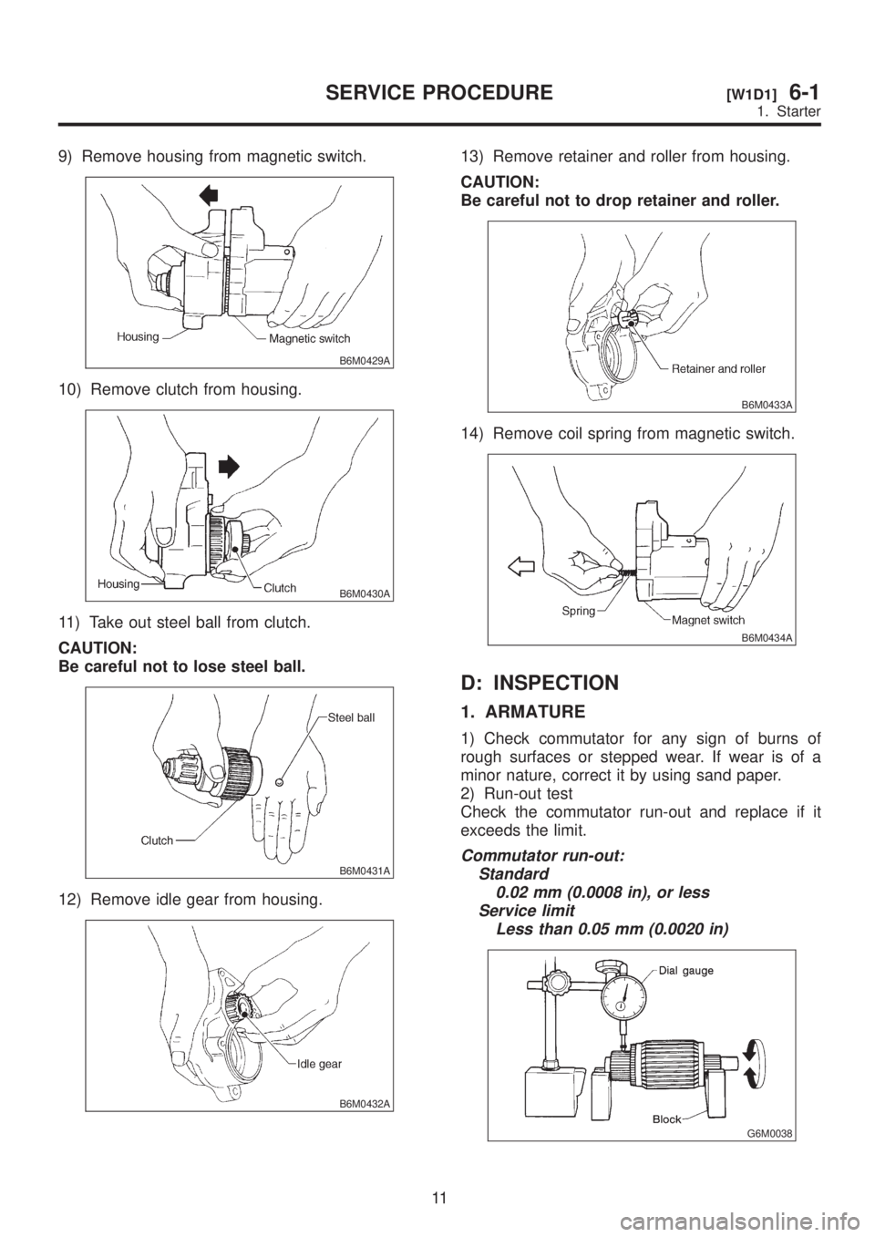
9) Remove housing from magnetic switch.
B6M0429A
10) Remove clutch from housing.
B6M0430A
11) Take out steel ball from clutch.
CAUTION:
Be careful not to lose steel ball.
B6M0431A
12) Remove idle gear from housing.
B6M0432A
13) Remove retainer and roller from housing.
CAUTION:
Be careful not to drop retainer and roller.
B6M0433A
14) Remove coil spring from magnetic switch.
B6M0434A
D: INSPECTION
1. ARMATURE
1) Check commutator for any sign of burns of
rough surfaces or stepped wear. If wear is of a
minor nature, correct it by using sand paper.
2) Run-out test
Check the commutator run-out and replace if it
exceeds the limit.
Commutator run-out:
Standard
0.02 mm (0.0008 in), or less
Service limit
Less than 0.05 mm (0.0020 in)
G6M0038
11
[W1D1]6-1SERVICE PROCEDURE
1. Starter
Page 1193 of 1456
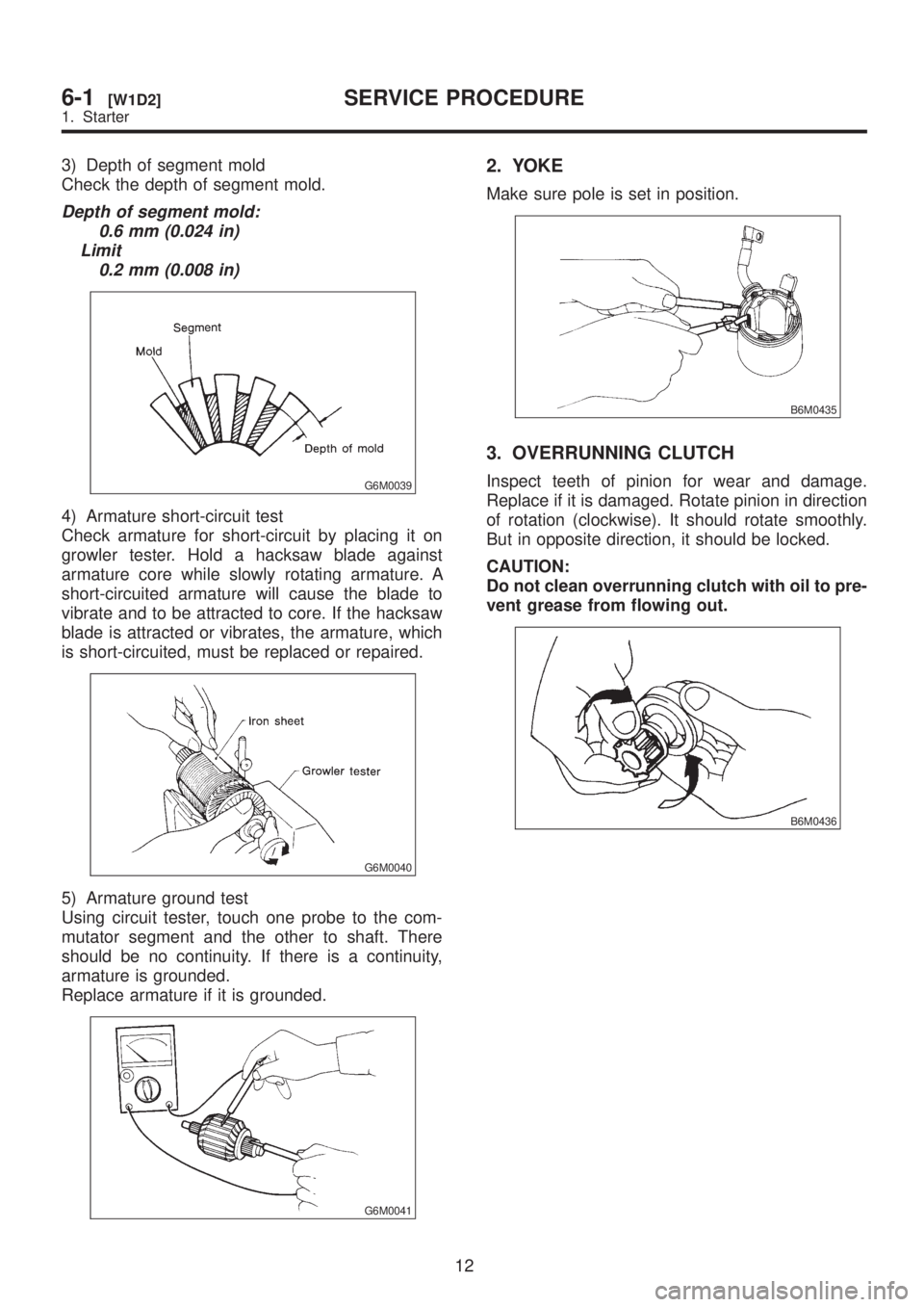
3) Depth of segment mold
Check the depth of segment mold.
Depth of segment mold:
0.6 mm (0.024 in)
Limit
0.2 mm (0.008 in)
G6M0039
4) Armature short-circuit test
Check armature for short-circuit by placing it on
growler tester. Hold a hacksaw blade against
armature core while slowly rotating armature. A
short-circuited armature will cause the blade to
vibrate and to be attracted to core. If the hacksaw
blade is attracted or vibrates, the armature, which
is short-circuited, must be replaced or repaired.
G6M0040
5) Armature ground test
Using circuit tester, touch one probe to the com-
mutator segment and the other to shaft. There
should be no continuity. If there is a continuity,
armature is grounded.
Replace armature if it is grounded.
G6M0041
2. YOKE
Make sure pole is set in position.
B6M0435
3. OVERRUNNING CLUTCH
Inspect teeth of pinion for wear and damage.
Replace if it is damaged. Rotate pinion in direction
of rotation (clockwise). It should rotate smoothly.
But in opposite direction, it should be locked.
CAUTION:
Do not clean overrunning clutch with oil to pre-
vent grease from flowing out.
B6M0436
12
6-1[W1D2]SERVICE PROCEDURE
1. Starter
Page 1194 of 1456
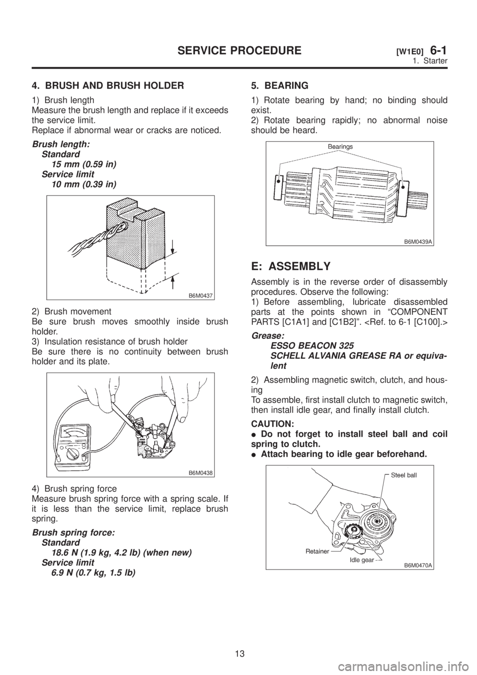
4. BRUSH AND BRUSH HOLDER
1) Brush length
Measure the brush length and replace if it exceeds
the service limit.
Replace if abnormal wear or cracks are noticed.
Brush length:
Standard
15 mm (0.59 in)
Service limit
10 mm (0.39 in)
B6M0437
2) Brush movement
Be sure brush moves smoothly inside brush
holder.
3) Insulation resistance of brush holder
Be sure there is no continuity between brush
holder and its plate.
B6M0438
4) Brush spring force
Measure brush spring force with a spring scale. If
it is less than the service limit, replace brush
spring.
Brush spring force:
Standard
18.6 N (1.9 kg, 4.2 lb) (when new)
Service limit
6.9 N (0.7 kg, 1.5 lb)
5. BEARING
1) Rotate bearing by hand; no binding should
exist.
2) Rotate bearing rapidly; no abnormal noise
should be heard.
B6M0439A
E: ASSEMBLY
Assembly is in the reverse order of disassembly
procedures. Observe the following:
1) Before assembling, lubricate disassembled
parts at the points shown in ªCOMPONENT
PARTS [C1A1] and [C1B2]º.
Grease:
ESSO BEACON 325
SCHELL ALVANIA GREASE RA or equiva-
lent
2) Assembling magnetic switch, clutch, and hous-
ing
To assemble, first install clutch to magnetic switch,
then install idle gear, and finally install clutch.
CAUTION:
IDo not forget to install steel ball and coil
spring to clutch.
IAttach bearing to idle gear beforehand.
B6M0470A
13
[W1E0]6-1SERVICE PROCEDURE
1. Starter
Page 1223 of 1456
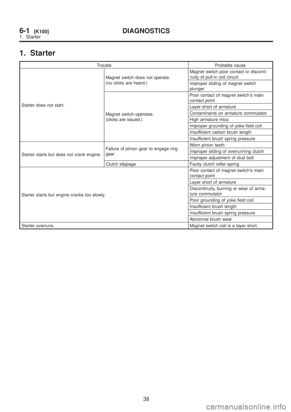
1. Starter
Trouble Probable cause
Starter does not start.Magnet switch does not operate.
(no clicks are heard.)Magnet switch poor contact or disconti-
nuity of pull-in coil circuit
Improper sliding of magnet switch
plunger
Magnet switch operates.
(clicks are issued.)Poor contact of magnet switch's main
contact point
Layer short of armature
Contaminants on armature commutator
High armature mica
Improper grounding of yoke field coil
Insufficient carbon brush length
Insufficient brush spring pressure
Starter starts but does not crank engine.Failure of pinion gear to engage ring
gearWorn pinion teeth
Improper sliding of overrunning clutch
Improper adjustment of stud bolt
Clutch slippage Faulty clutch roller spring
Starter starts but engine cranks too slowly.Poor contact of magnet switch's main
contact point
Layer short of armature
Discontinuity, burning or wear of arma-
ture commutator
Poor grounding of yoke field coil
Insufficient brush length
Insufficient brush spring pressure
Abnormal brush wear
Starter overruns. Magnet switch coil is a layer short.
38
6-1[K100]DIAGNOSTICS
1. Starter
Page 1273 of 1456
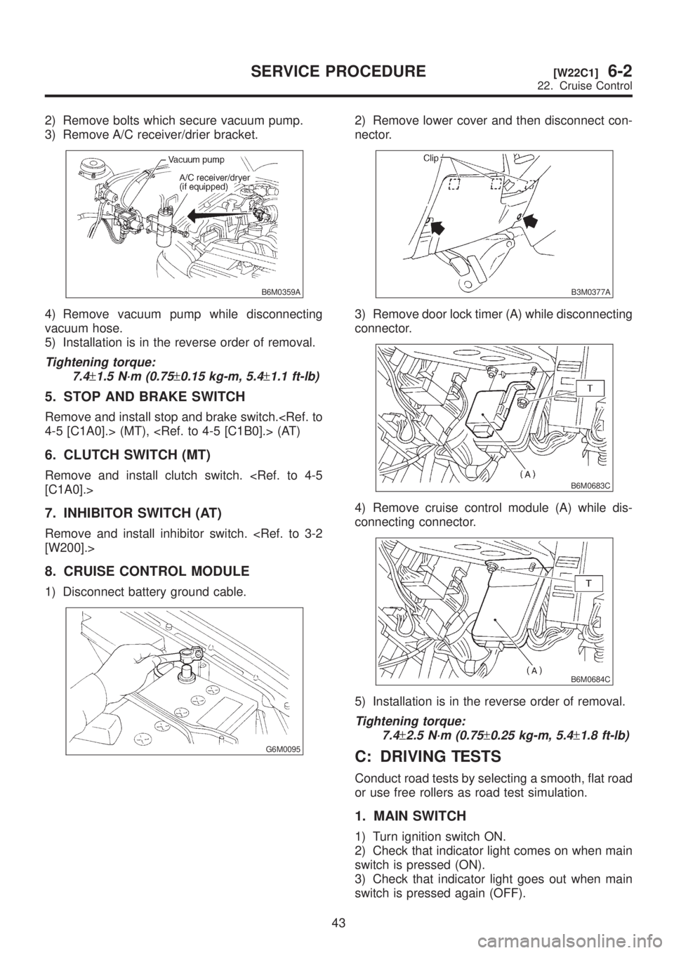
2) Remove bolts which secure vacuum pump.
3) Remove A/C receiver/drier bracket.
B6M0359A
4) Remove vacuum pump while disconnecting
vacuum hose.
5) Installation is in the reverse order of removal.
Tightening torque:
7.4
±1.5 N´m (0.75±0.15 kg-m, 5.4±1.1 ft-lb)
5. STOP AND BRAKE SWITCH
Remove and install stop and brake switch.
6. CLUTCH SWITCH (MT)
Remove and install clutch switch.
7. INHIBITOR SWITCH (AT)
Remove and install inhibitor switch.
8. CRUISE CONTROL MODULE
1) Disconnect battery ground cable.
G6M0095
2) Remove lower cover and then disconnect con-
nector.
B3M0377A
3) Remove door lock timer (A) while disconnecting
connector.
B6M0683C
4) Remove cruise control module (A) while dis-
connecting connector.
B6M0684C
5) Installation is in the reverse order of removal.
Tightening torque:
7.4
±2.5 N´m (0.75±0.25 kg-m, 5.4±1.8 ft-lb)
C: DRIVING TESTS
Conduct road tests by selecting a smooth, flat road
or use free rollers as road test simulation.
1. MAIN SWITCH
1) Turn ignition switch ON.
2) Check that indicator light comes on when main
switch is pressed (ON).
3) Check that indicator light goes out when main
switch is pressed again (OFF).
43
[W22C1]6-2SERVICE PROCEDURE
22. Cruise Control
Page 1413 of 1456
![SUBARU LEGACY 1999 Service Repair Manual 7. Electrical Unit Location
A: LIST
Electrical unit Index No.
ABS control module <Ref. to 4-4 [T300].>
ABS G sensor (MT) <Ref. to 4-4 [T300].>
A/C compressor relay <Ref. to 6-3 [D7B1].>
A/C fuse <Ref.](/img/17/57435/w960_57435-1412.png "SUBARU LEGACY 1999 Service Repair Manual 7. Electrical Unit Location
A: LIST
Electrical unit Index No.
ABS control module <Ref. to 4-4 [T300].>
ABS G sensor (MT) <Ref. to 4-4 [T300].>
A/C compressor relay <Ref. to 6-3 [D7B1].>
A/C fuse <Ref.")
7. Electrical Unit Location
A: LIST
Electrical unit Index No.
ABS control module
ABS G sensor (MT)
A/C compressor relay
A/C fuse
A/C main fan relay 1
A/C main fan relay 2
A/C pressure switch
A/C sub fan relay 2
ATF temperature sensor
Blower motor resistor
Blower relay
Camshaft position sensor
Check connector
Clutch switch (MT)
Crankshaft position sensor
Cruise control module
Cruise control pump
Data link connector (for
OBD-II G.S.T.)
Data link connector (for
S.S.M.)
Diagnosis connector
Diagnosis terminal (Ground)
Door lock timer
Engine control module
Engine coolant temperature
sensor
Engine hood switch (Secu-
rity)
Evaporator thermoswitch
F/B
FRESH/RECIRC actuator
Fuel pump relay
Fuel gauge module
Fuel gauge sub module
(AWD)
FWD switch (AT)
Headlight alarm relay
(Security)
Headlight relay LH
Electrical unit Index No.
Headlight relay RH
Horn relay
Hydraulic unit (ABS)
Ignition coil
Ignitor
Idle air control solenoid
valve
Illumination control module
Inhibitor switch
Knock sensor
Main fan relay
Main relay
Mass air flow sensor
Mode actuator
M/B
Oil pressure switch
Oxygen sensor
Pedal stroke sensor (TCS)
Power window and sunroof
relay
Power window circuit
breaker
Purge control solenoid valve
Rear defogger relay
Seat belt timer
Security control module
Shift lock control module
Starter interrupt relay (Secu-
rity)
Stop & brake switch (With
cruise control)
Sunroof control module
Tail and illumination relay
TCS control module
TCS motor relay
TCS valve relay
Throttle position sensor
Test mode connector
Transmission control mod-
ule
Turn & hazard module
Vehicle speed sensor 1
Vehicle speed sensor 2
133
[D7A0]6-3WIRING DIAGRAM
7. Electrical Unit Location
Page 1430 of 1456
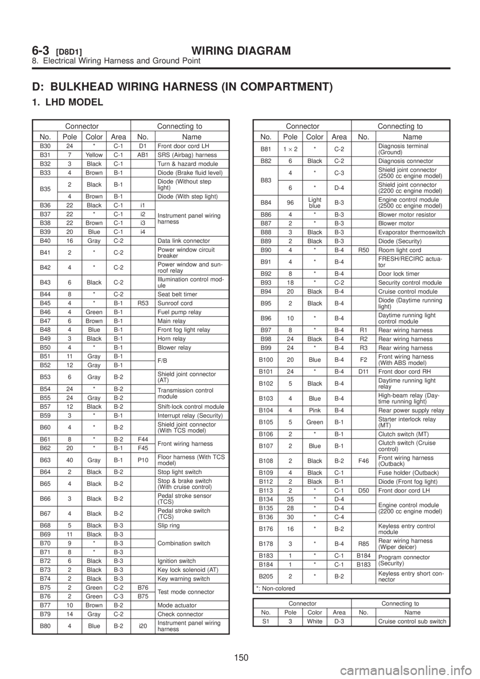
D: BULKHEAD WIRING HARNESS (IN COMPARTMENT)
1. LHD MODEL
Connector Connecting to
No. Pole Color Area No. Name
B30 24 * C-1 D1 Front door cord LH
B31 7 Yellow C-1 AB1 SRS (Airbag) harness
B32 3 Black C-1 Turn & hazard module
B33 4 Brown B-1 Diode (Brake fluid level)
B352 Black B-1Diode (Without step
light)
4 Brown B-1 Diode (With step light)
B36 22 Black C-1 i1
Instrument panel wiring
harness B37 22 * C-1 i2
B38 22 Brown C-1 i3
B39 20 Blue C-1 i4
B40 16 Gray C-2 Data link connector
B41 2 * C-2Power window circuit
breaker
B42 4 * C-2Power window and sun-
roof relay
B43 6 Black C-2Illumination control mod-
ule
B44 8 * C-2 Seat belt timer
B45 4 * B-1 R53 Sunroof cord
B46 4 Green B-1 Fuel pump relay
B47 6 Brown B-1 Main relay
B48 4 Blue B-1 Front fog light relay
B49 3 Black B-1 Horn relay
B50 4 * B-1 Blower relay
B51 11 Gray B-1
F/B
B52 12 Gray B-1
B53 6 Gray B-2Shield joint connector
(AT)
B54 24 * B-2
Transmission control
module
B55 24 Gray B-2
B57 12 Black B-2 Shift-lock control module
B59 3 * B-1 Interrupt relay (Security)
B60 4 * B-2Shield joint connector
(With TCS model)
B61 8 * B-2 F44
Front wiring harness
B62 20 * B-1 F45
B63 40 Gray B-1 P10Floor harness (With TCS
model)
B64 2 Black B-2 Stop light switch
B65 4 Black B-2Stop & brake switch
(With cruise control)
B66 3 Black B-2Pedal stroke sensor
(TCS)
B67 4 Black B-2Pedal stroke switch
(TCS)
B68 5 Black B-3 Slip ring
B69 11 Black B-3
Combination switch B70 9 * B-3
B71 8 * B-3
B72 6 Black B-3 Ignition switch
B73 2 Black B-3 Key lock solenoid (AT)
B74 2 Black B-3 Key warning switch
B75 2 Green C-2 B76
Test mode connector
B76 2 Green C-3 B75
B77 10 Brown B-2 Mode actuator
B79 14 Gray C-2 Check connector
B80 4 Blue B-2 i20Instrument panel wiring
harness
Connector Connecting to
No. Pole Color Area No. Name
B81 1´2 * C-2Diagnosis terminal
(Ground)
B82 6 Black C-2 Diagnosis connector
B834 * C-3Shield joint connector
(2500 cc engine model)
6 * D-4Shield joint connector
(2200 cc engine model)
B84 96Light
blueB-3Engine control module
(2500 cc engine model)
B86 4 * B-3 Blower motor resistor
B87 2 * B-3 Blower motor
B88 3 Black B-3 Evaporator thermoswitch
B89 2 Black B-3 Diode (Security)
B90 4 * B-4 R50 Room light cord
B91 4 * B-4FRESH/RECIRC actua-
tor
B92 8 * B-4 Door lock timer
B93 18 * C-2 Security control module
B94 20 Black B-4 Cruise control module
B95 2 Black B-4Diode (Daytime running
light)
B96 10 * B-4Daytime running light
control module
B97 8 * B-4 R1 Rear wiring harness
B98 24 Black B-4 R2 Rear wiring harness
B99 24 * B-4 R3 Rear wiring harness
B100 20 Blue B-4 F2Front wiring harness
(With ABS model)
B101 24 * B-4 D11 Front door cord RH
B102 5 Black B-4Daytime running light
relay
B103 4 Blue B-4High-beam relay (Day-
time running light)
B104 4 Pink B-4 Rear power supply relay
B105 5 Green B-1Starter interlock relay
(MT)
B106 2 * B-1 Clutch switch (MT)
B107 2 Blue B-1Clutch switch (Cruise
control)
B108 2 Black B-2 F46Front wiring harness
(Outback)
B109 4 Black C-1 Fuse holder (Outback)
B112 2 Black B-1 Diode (Front fog light)
B113 2 * C-1 D50 Front door cord LH
B134 35 * D-4
Engine control module
(2200 cc engine model) B135 28 * D-4
B136 30 * C-4
B176 16 * B-2Keyless entry control
module
B178 3 * B-4 R85Rear wiring harness
(Wiper deicer)
B183 1 * C-1 B184
Program connector
(Security)
B184 1 * C-1 B183
B205 2 * B-2Keyless entry short con-
nector
*: Non-colored
Connector Connecting to
No. Pole Color Area No. Name
S1 3 White D-3 Cruise control sub switch
150
6-3[D8D1]WIRING DIAGRAM
8. Electrical Wiring Harness and Ground Point