parking brake SUBARU LEGACY 1999 Service Repair Manual
[x] Cancel search | Manufacturer: SUBARU, Model Year: 1999, Model line: LEGACY, Model: SUBARU LEGACY 1999Pages: 1456, PDF Size: 59.93 MB
Page 373 of 1456
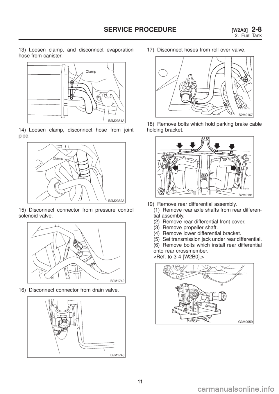
13) Loosen clamp, and disconnect evaporation
hose from canister.
B2M2381A
14) Loosen clamp, disconnect hose from joint
pipe.
B2M2382A
15) Disconnect connector from pressure control
solenoid valve.
B2M1742
16) Disconnect connector from drain valve.
B2M1743
17) Disconnect hoses from roll over valve.
S2M0167
18) Remove bolts which hold parking brake cable
holding bracket.
S2M0191
19) Remove rear differential assembly.
(1) Remove rear axle shafts from rear differen-
tial assembly.
(2) Remove rear differential front cover.
(3) Remove propeller shaft.
(4) Remove lower differential bracket.
(5) Set transmission jack under rear differential.
(6) Remove bolts which install rear differential
onto rear crossmember.
G3M0059
11
[W2A0]2-8SERVICE PROCEDURE
2. Fuel Tank
Page 376 of 1456
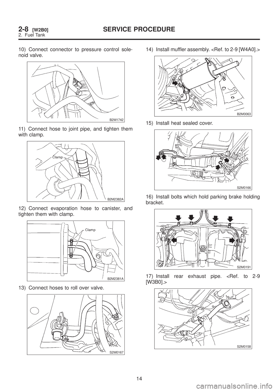
10) Connect connector to pressure control sole-
noid valve.
B2M1742
11) Connect hose to joint pipe, and tighten them
with clamp.
B2M2382A
12) Connect evaporation hose to canister, and
tighten them with clamp.
B2M2381A
13) Connect hoses to roll over valve.
S2M0167
14) Install muffler assembly.
B2M0063
15) Install heat sealed cover.
S2M0166
16) Install bolts which hold parking brake holding
bracket.
S2M0191
17) Install rear exhaust pipe.
S2M0158
14
2-8[W2B0]SERVICE PROCEDURE
2. Fuel Tank
Page 430 of 1456
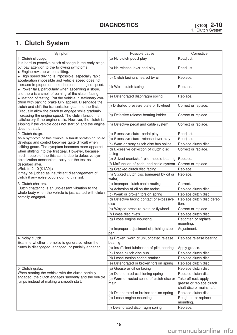
1. Clutch System
Symptom Possible cause Corrective
1. Clutch slippage.
It is hard to perceive clutch slippage in the early stage,
but pay attention to the following symptoms
IEngine revs up when shifting.
IHigh speed driving is impossible; especially rapid
acceleration impossible and vehicle speed does not
increase in proportion to an increase in engine speed.
IPower falls, particularly when ascending a slope,
and there is a smell of burning of the clutch facing.
IMethod of testing: Put the vehicle in stationary con-
dition with parking brake fully applied. Disengage the
clutch and shift the transmission gear into the first.
Gradually allow the clutch to engage while gradually
increasing the engine speed. The clutch function is
satisfactory if the engine stalls. However, the clutch is
slipping if the vehicle does not start off and the engine
does not stall.(a) No clutch pedal play Readjust.
(b) No release lever end play Readjust.
(c) Clutch facing smeared by oil Replace.
(d) Worn clutch facing Replace.
(e) Deteriorated diaphragm spring Replace.
(f) Distorted pressure plate or flywheel Correct or replace.
(g) Defective release bearing holder Correct or replace.
(h) Defective pedal and cable system Correct or replace.
2. Clutch drags.
As a symptom of this trouble, a harsh scratching noise
develops and control becomes quite difficult when
shifting gears. The symptom becomes more apparent
when shifting into the first gear. However, because
much trouble of the this sort is due to defective syn-
chronization mechanism, carry out the test as
described after.
It may be judged as insufficient disengagement of
clutch if any noise occurs during this test.(a) Excessive clutch pedal play Readjust.
(b) Excessive clutch release lever play Readjust.
(c) Worn or rusty clutch disc hub spline Replace clutch disc.
(d) Excessive deflection of clutch disc
facingCorrect or replace.
(e) Seized crankshaft pilot needle bearing Replace.
(f) Malfunction of pedal and cable system Correct or replace.
(g) Cracked clutch disc facing Replace.
(h) Sticked clutch disc (smeared by oil or
water)Replace.
3. Clutch chatters.
Clutch chattering is an unpleasant vibration to the
whole body when the vehicle is just started with clutch
partially engaged.(a) Improper clutch cable routing Correct.
(b) Adhesion of oil on the facing Replace clutch disc.
(c) Weak or broken torsion spring Replace clutch disc.
(d) Defective facing contact or excessive
discReplace clutch disc defec-
tion.
(e) Warped pressure plate or flywheel Correct or replace.
(f) Loose disc rivets Replace clutch disc.
(g) Loose engine mounting Retighten or replace
mounting.
(h) Improper adjustment of pitching stop-
perAdjustment.
4. Noisy clutch
Examine whether the noise is generated when the
clutch is disengaged, engaged, or partially engaged.(a) Broken, worn or unlubricated release
bearingReplace release bearing.
(b) Insufficient lubrication of pilot bearing Apply grease.
(c) Loose clutch disc hub Replace clutch disc.
(d) Loose torsion spring retainer Replace clutch disc.
(e) Deteriorated or broken torsion spring Replace clutch disc.
5. Clutch grabs.
When starting the vehicle with the clutch partially
engaged, the clutch engages suddenly and the vehicle
jumps instead of making a smooth start.(a) Grease or oil on facing Replace clutch disc.
(b) Deteriorated cushioning spring Replace clutch disc.
(c) Worn or rusted spline of clutch disc or
mainTake off rust, apply
grease or replace clutch
shaft disc or mainshaft.
(d) Deteriorated or broken torsion spring Replace clutch disc.
(e) Loose engine mounting Retighten or replace
mounting.
(f) Deteriorated diaphragm spring Replace.
19
[K100]2-10DIAGNOSTICS
1. Clutch System
Page 570 of 1456
stall speed range on the tachometer scale.
3) Place the wheel chocks at the front and rear of
all wheels and engage the parking brake.
4) Move the manual linkage to ensure it operates
properly, and shift the select lever to the 2 range.
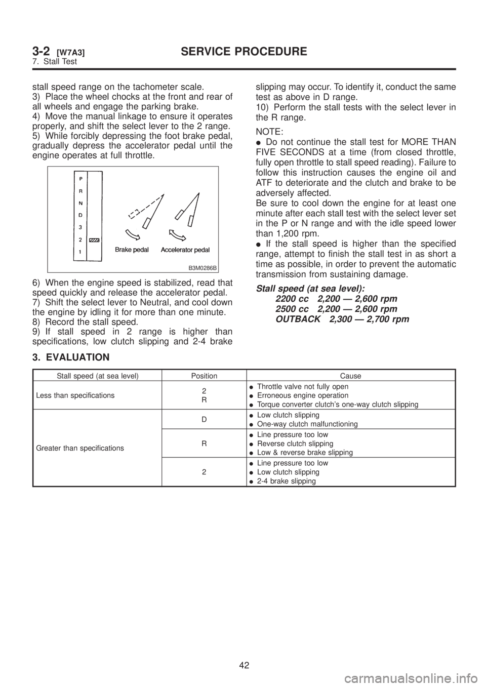
5) While forcibly depressing the foot brake pedal,
gradually depress the accelerator pedal until the
engine operates at full throttle.
B3M0286B
6) When the engine speed is stabilized, read that
speed quickly and release the accelerator pedal.
7) Shift the select lever to Neutral, and cool down
the engine by idling it for more than one minute.
8) Record the stall speed.
9) If stall speed in 2 range is higher than
specifications, low clutch slipping and 2-4 brakeslipping may occur. To identify it, conduct the same
test as above in D range.
10) Perform the stall tests with the select lever in
the R range.
NOTE:
IDo not continue the stall test for MORE THAN
FIVE SECONDS at a time (from closed throttle,
fully open throttle to stall speed reading). Failure to
follow this instruction causes the engine oil and
ATF to deteriorate and the clutch and brake to be
adversely affected.
Be sure to cool down the engine for at least one
minute after each stall test with the select lever set
in the P or N range and with the idle speed lower
than 1,200 rpm.
IIf the stall speed is higher than the specified
range, attempt to finish the stall test in as short a
time as possible, in order to prevent the automatic
transmission from sustaining damage.Stall speed (at sea level):
2200 cc 2,200 Ð 2,600 rpm
2500 cc 2,200 Ð 2,600 rpm
OUTBACK 2,300 Ð 2,700 rpm
3. EVALUATION
Stall speed (at sea level) Position Cause
Less than specifications2
RIThrottle valve not fully open
IErroneous engine operation
ITorque converter clutch's one-way clutch slipping
Greater than specificationsDILow clutch slipping
IOne-way clutch malfunctioning
RILine pressure too low
IReverse clutch slipping
ILow & reverse brake slipping
2ILine pressure too low
ILow clutch slipping
I2-4 brake slipping
42
3-2[W7A3]SERVICE PROCEDURE
7. Stall Test
Page 571 of 1456
8. Time Lag Test
A: INSPECTION
1. GENERAL INFORMATION
If the shift lever is shifted while the engine is idling,
there will be a certain time elapse or lag before the
shock can be felt. This is used for checking the
condition of the low clutch, reverse clutch, low &
reverse brake and one-way clutch.
CAUTION:
IPerform the test at normal operation fluid
temperature 60 to 80ÉC (140 to 176ÉF).
IBe sure to allow a one minute interval
between tests.
IMake three measurements and take the aver-
age value.
2. TEST METHODS
1) Fully apply the parking brake.
2) Start the engine.
Check idling speed (A/C OFF).
ªNº range: 800±100 rpm
3) Shift the shift lever from ªNº to ªDº range.
Using a stop watch, measure the time it takes from
shifting the lever until the shock is felt.
Time lag: Less than 1.2 seconds
4) In same manner, measure the time lag for ªNº
®ªRº.
Time lag: Less than 1.5 seconds
3. EVALUATION
1) If ªNº®ªDº time lag is longer than specified:
ILine pressure too low
ILow clutch worn
IOne-way clutch not operating properly
2) If ªNº®ªRº time lag is longer than specified:
ILine pressure too low
IReverse clutch worn
ILow & reverse brake worn
9. Line Pressure Test
A: MEASUREMENT
1. GENERAL INFORMATION
If the clutch or the brake shows a sign of slippage
or shifting sensation is not correct, the line pres-
sure should be checked.
IExcessive shocks during upshifting or shifting
takes place at a higher point than under normal
circumstances, may be due to the line pressure
being too high.
ISlippage or inability to operate the vehicle may,
in most cases, be due to loss of oil pressure for the
operation of the clutch, brake or control valve.
1) Line pressure measurement (under no load)
CAUTION:
IBefore measuring line pressure, jack-up all
wheels.
IMaintain temperature of ATF at approxi-
mately 50ÉC (122ÉF) during measurement.
(ATF will reach the above temperature after
idling the engine for approximately 30 minutes
with select lever in ªNº or ªPº.)
2) Line pressure measurement (under heavy load)
CAUTION:
IBefore measuring line pressure, apply both
foot and parking brakes with all wheels
chocked (Same as for ªstallº test conditions).
IMeasure line pressure when select lever is in
ªRº, ª2º with engine under stall conditions.
IMeasure line pressure within 5 seconds after
shifting the select lever to each position. (If line
pressure needs to be measured again, allow
the engine to idle and then stop. Wait for at
least one minute before measurement.)
IMaintain the temperature of ATF at approxi-
mately 50ÉC (122ÉF) during measurement. (ATF
will reach the above temperature after idling
the engine for approximately 30 minutes with
the select lever in ªNº or ªPº.)
43
[W9A1]3-2SERVICE PROCEDURE
9. Line Pressure Test
Page 572 of 1456
8. Time Lag Test
A: INSPECTION
1. GENERAL INFORMATION
If the shift lever is shifted while the engine is idling,
there will be a certain time elapse or lag before the
shock can be felt. This is used for checking the
condition of the low clutch, reverse clutch, low &
reverse brake and one-way clutch.
CAUTION:
IPerform the test at normal operation fluid
temperature 60 to 80ÉC (140 to 176ÉF).
IBe sure to allow a one minute interval
between tests.
IMake three measurements and take the aver-
age value.
2. TEST METHODS
1) Fully apply the parking brake.
2) Start the engine.
Check idling speed (A/C OFF).
ªNº range: 800±100 rpm
3) Shift the shift lever from ªNº to ªDº range.
Using a stop watch, measure the time it takes from
shifting the lever until the shock is felt.
Time lag: Less than 1.2 seconds
4) In same manner, measure the time lag for ªNº
®ªRº.
Time lag: Less than 1.5 seconds
3. EVALUATION
1) If ªNº®ªDº time lag is longer than specified:
ILine pressure too low
ILow clutch worn
IOne-way clutch not operating properly
2) If ªNº®ªRº time lag is longer than specified:
ILine pressure too low
IReverse clutch worn
ILow & reverse brake worn
9. Line Pressure Test
A: MEASUREMENT
1. GENERAL INFORMATION
If the clutch or the brake shows a sign of slippage
or shifting sensation is not correct, the line pres-
sure should be checked.
IExcessive shocks during upshifting or shifting
takes place at a higher point than under normal
circumstances, may be due to the line pressure
being too high.
ISlippage or inability to operate the vehicle may,
in most cases, be due to loss of oil pressure for the
operation of the clutch, brake or control valve.
1) Line pressure measurement (under no load)
CAUTION:
IBefore measuring line pressure, jack-up all
wheels.
IMaintain temperature of ATF at approxi-
mately 50ÉC (122ÉF) during measurement.
(ATF will reach the above temperature after
idling the engine for approximately 30 minutes
with select lever in ªNº or ªPº.)
2) Line pressure measurement (under heavy load)
CAUTION:
IBefore measuring line pressure, apply both
foot and parking brakes with all wheels
chocked (Same as for ªstallº test conditions).
IMeasure line pressure when select lever is in
ªRº, ª2º with engine under stall conditions.
IMeasure line pressure within 5 seconds after
shifting the select lever to each position. (If line
pressure needs to be measured again, allow
the engine to idle and then stop. Wait for at
least one minute before measurement.)
IMaintain the temperature of ATF at approxi-
mately 50ÉC (122ÉF) during measurement. (ATF
will reach the above temperature after idling
the engine for approximately 30 minutes with
the select lever in ªNº or ªPº.)
43
[W9A1]3-2SERVICE PROCEDURE
9. Line Pressure Test
Page 582 of 1456
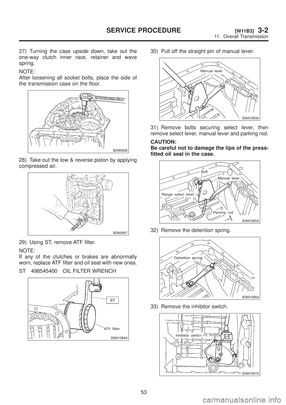
27) Turning the case upside down, take out the
one-way clutch inner race, retainer and wave
spring.
NOTE:
After loosening all socket bolts, place the side of
the transmission case on the floor.
B3M0958
28) Take out the low & reverse piston by applying
compressed air.
B3M0957
29) Using ST, remove ATF filter.
NOTE:
If any of the clutches or brakes are abnormally
worn, replace ATF filter and oil seal with new ones.
ST 498545400 OIL FILTER WRENCH
B3M1084A
30) Pull off the straight pin of manual lever.
B3M1083A
31) Remove bolts securing select lever, then
remove select lever, manual lever and parking rod.
CAUTION:
Be careful not to damage the lips of the press-
fitted oil seal in the case.
B3M1085A
32) Remove the detention spring.
B3M1086A
33) Remove the inhibitor switch.
B3M1087A
53
[W11B3]3-2SERVICE PROCEDURE
11. Overall Transmission
Page 661 of 1456
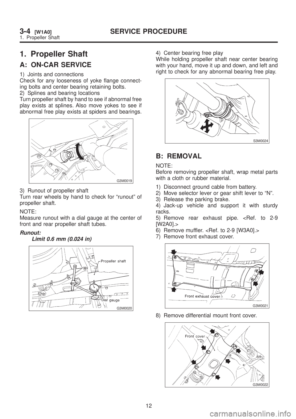
1. Propeller Shaft
A: ON-CAR SERVICE
1) Joints and connections
Check for any looseness of yoke flange connect-
ing bolts and center bearing retaining bolts.
2) Splines and bearing locations
Turn propeller shaft by hand to see if abnormal free
play exists at splines. Also move yokes to see if
abnormal free play exists at spiders and bearings.
G3M0019
3) Runout of propeller shaft
Turn rear wheels by hand to check for ªrunoutº of
propeller shaft.
NOTE:
Measure runout with a dial gauge at the center of
front and rear propeller shaft tubes.
Runout:
Limit 0.6 mm (0.024 in)
G3M0020
4) Center bearing free play
While holding propeller shaft near center bearing
with your hand, move it up and down, and left and
right to check for any abnormal bearing free play.
S3M0024
B: REMOVAL
NOTE:
Before removing propeller shaft, wrap metal parts
with a cloth or rubber material.
1) Disconnect ground cable from battery.
2) Move selector lever or gear shift lever to ªNº.
3) Release the parking brake.
4) Jack-up vehicle and support it with sturdy
racks.
5) Remove rear exhaust pipe.
6) Remove muffler.
7) Remove front exhaust cover.
G3M0021
8) Remove differential mount front cover.
G3M0022
12
3-4[W1A0]SERVICE PROCEDURE
1. Propeller Shaft
Page 663 of 1456
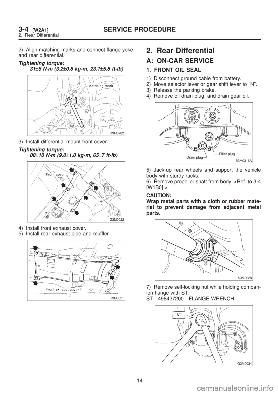
2) Align matching marks and connect flange yoke
and rear differential.
Tightening torque:
31
±8 N´m (3.2±0.8 kg-m, 23.1±5.8 ft-lb)
G3M0782
3) Install differential mount front cover.
Tightening torque:
88
±10 N´m (9.0±1.0 kg-m, 65±7 ft-lb)
G3M0022
4) Install front exhaust cover.
5) Install rear exhaust pipe and muffler.
G3M0021
2. Rear Differential
A: ON-CAR SERVICE
1. FRONT OIL SEAL
1) Disconnect ground cable from battery.
2) Move selector lever or gear shift lever to ªNº.
3) Release the parking brake.
4) Remove oil drain plug, and drain gear oil.
B3M0316A
5) Jack-up rear wheels and support the vehicle
body with sturdy racks.
6) Remove propeller shaft from body.
CAUTION:
Wrap metal parts with a cloth or rubber mate-
rial to prevent damage from adjacent metal
parts.
S3M0028
7) Remove self-locking nut while holding compan-
ion flange with ST.
ST 498427200 FLANGE WRENCH
G3M0034
14
3-4[W2A1]SERVICE PROCEDURE
2. Rear Differential
Page 664 of 1456
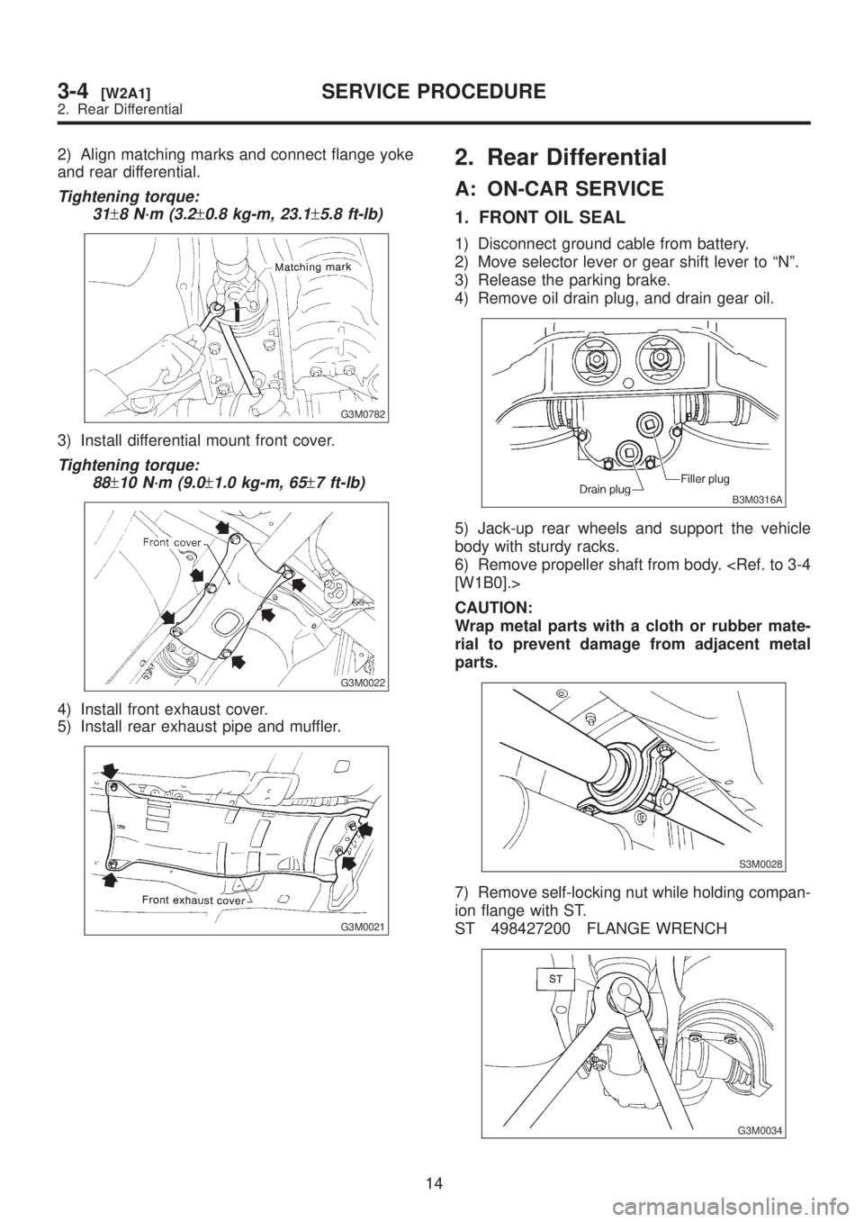
2) Align matching marks and connect flange yoke
and rear differential.
Tightening torque:
31
±8 N´m (3.2±0.8 kg-m, 23.1±5.8 ft-lb)
G3M0782
3) Install differential mount front cover.
Tightening torque:
88
±10 N´m (9.0±1.0 kg-m, 65±7 ft-lb)
G3M0022
4) Install front exhaust cover.
5) Install rear exhaust pipe and muffler.
G3M0021
2. Rear Differential
A: ON-CAR SERVICE
1. FRONT OIL SEAL
1) Disconnect ground cable from battery.
2) Move selector lever or gear shift lever to ªNº.
3) Release the parking brake.
4) Remove oil drain plug, and drain gear oil.
B3M0316A
5) Jack-up rear wheels and support the vehicle
body with sturdy racks.
6) Remove propeller shaft from body.
CAUTION:
Wrap metal parts with a cloth or rubber mate-
rial to prevent damage from adjacent metal
parts.
S3M0028
7) Remove self-locking nut while holding compan-
ion flange with ST.
ST 498427200 FLANGE WRENCH
G3M0034
14
3-4[W2A1]SERVICE PROCEDURE
2. Rear Differential