wheel SUBARU LEGACY 1999 Service Repair Manual
[x] Cancel search | Manufacturer: SUBARU, Model Year: 1999, Model line: LEGACY, Model: SUBARU LEGACY 1999Pages: 1456, PDF Size: 59.93 MB
Page 1178 of 1456
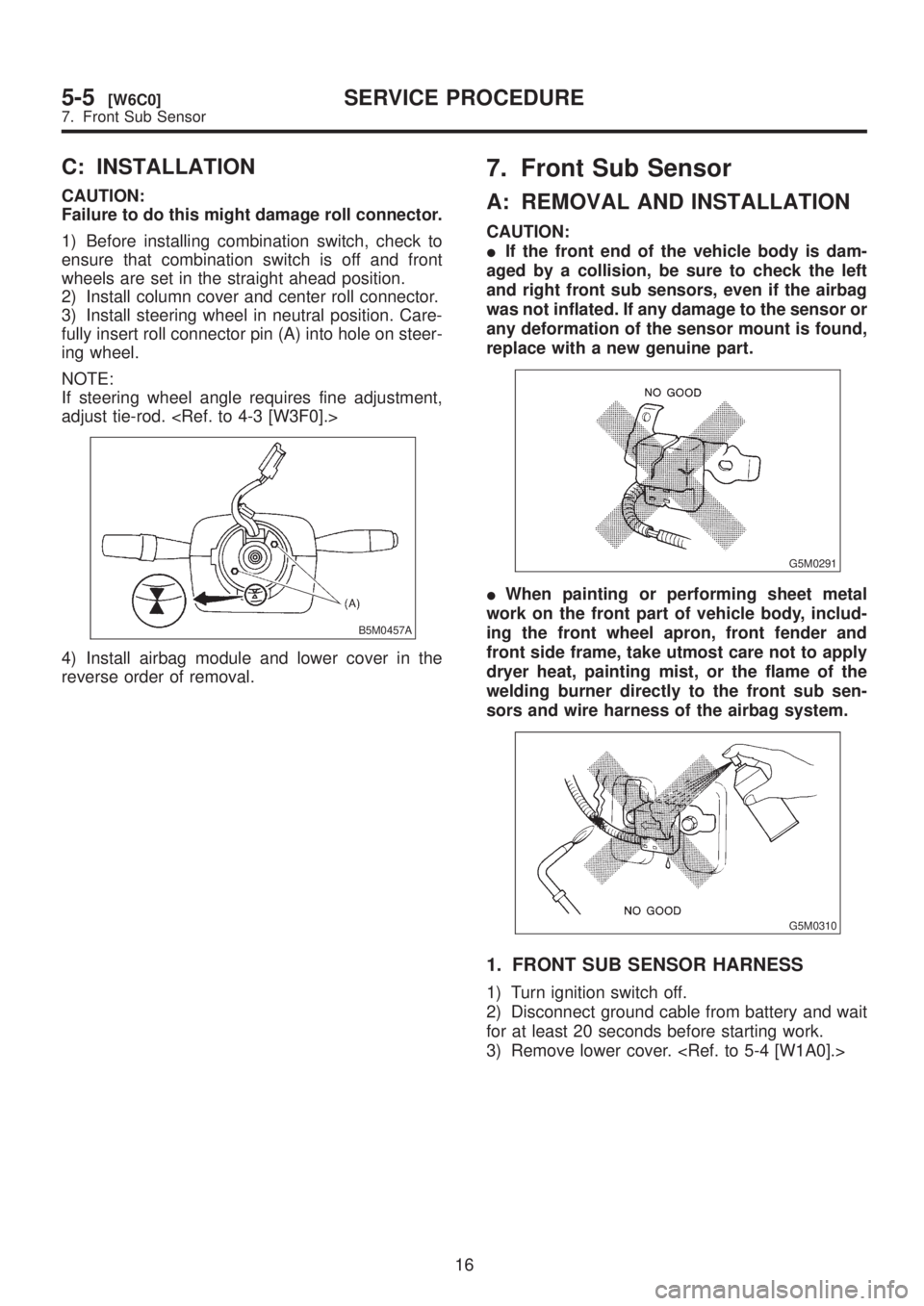
C: INSTALLATION
CAUTION:
Failure to do this might damage roll connector.
1) Before installing combination switch, check to
ensure that combination switch is off and front
wheels are set in the straight ahead position.
2) Install column cover and center roll connector.
3) Install steering wheel in neutral position. Care-
fully insert roll connector pin (A) into hole on steer-
ing wheel.
NOTE:
If steering wheel angle requires fine adjustment,
adjust tie-rod.
B5M0457A
4) Install airbag module and lower cover in the
reverse order of removal.
7. Front Sub Sensor
A: REMOVAL AND INSTALLATION
CAUTION:
IIf the front end of the vehicle body is dam-
aged by a collision, be sure to check the left
and right front sub sensors, even if the airbag
was not inflated. If any damage to the sensor or
any deformation of the sensor mount is found,
replace with a new genuine part.
G5M0291
IWhen painting or performing sheet metal
work on the front part of vehicle body, includ-
ing the front wheel apron, front fender and
front side frame, take utmost care not to apply
dryer heat, painting mist, or the flame of the
welding burner directly to the front sub sen-
sors and wire harness of the airbag system.
G5M0310
1. FRONT SUB SENSOR HARNESS
1) Turn ignition switch off.
2) Disconnect ground cable from battery and wait
for at least 20 seconds before starting work.
3) Remove lower cover.
16
5-5[W6C0]SERVICE PROCEDURE
7. Front Sub Sensor
Page 1179 of 1456
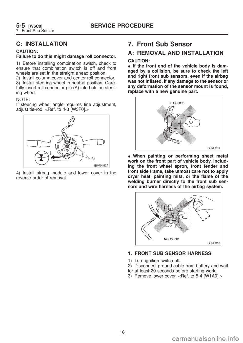
C: INSTALLATION
CAUTION:
Failure to do this might damage roll connector.
1) Before installing combination switch, check to
ensure that combination switch is off and front
wheels are set in the straight ahead position.
2) Install column cover and center roll connector.
3) Install steering wheel in neutral position. Care-
fully insert roll connector pin (A) into hole on steer-
ing wheel.
NOTE:
If steering wheel angle requires fine adjustment,
adjust tie-rod.
B5M0457A
4) Install airbag module and lower cover in the
reverse order of removal.
7. Front Sub Sensor
A: REMOVAL AND INSTALLATION
CAUTION:
IIf the front end of the vehicle body is dam-
aged by a collision, be sure to check the left
and right front sub sensors, even if the airbag
was not inflated. If any damage to the sensor or
any deformation of the sensor mount is found,
replace with a new genuine part.
G5M0291
IWhen painting or performing sheet metal
work on the front part of vehicle body, includ-
ing the front wheel apron, front fender and
front side frame, take utmost care not to apply
dryer heat, painting mist, or the flame of the
welding burner directly to the front sub sen-
sors and wire harness of the airbag system.
G5M0310
1. FRONT SUB SENSOR HARNESS
1) Turn ignition switch off.
2) Disconnect ground cable from battery and wait
for at least 20 seconds before starting work.
3) Remove lower cover.
16
5-5[W6C0]SERVICE PROCEDURE
7. Front Sub Sensor
Page 1180 of 1456
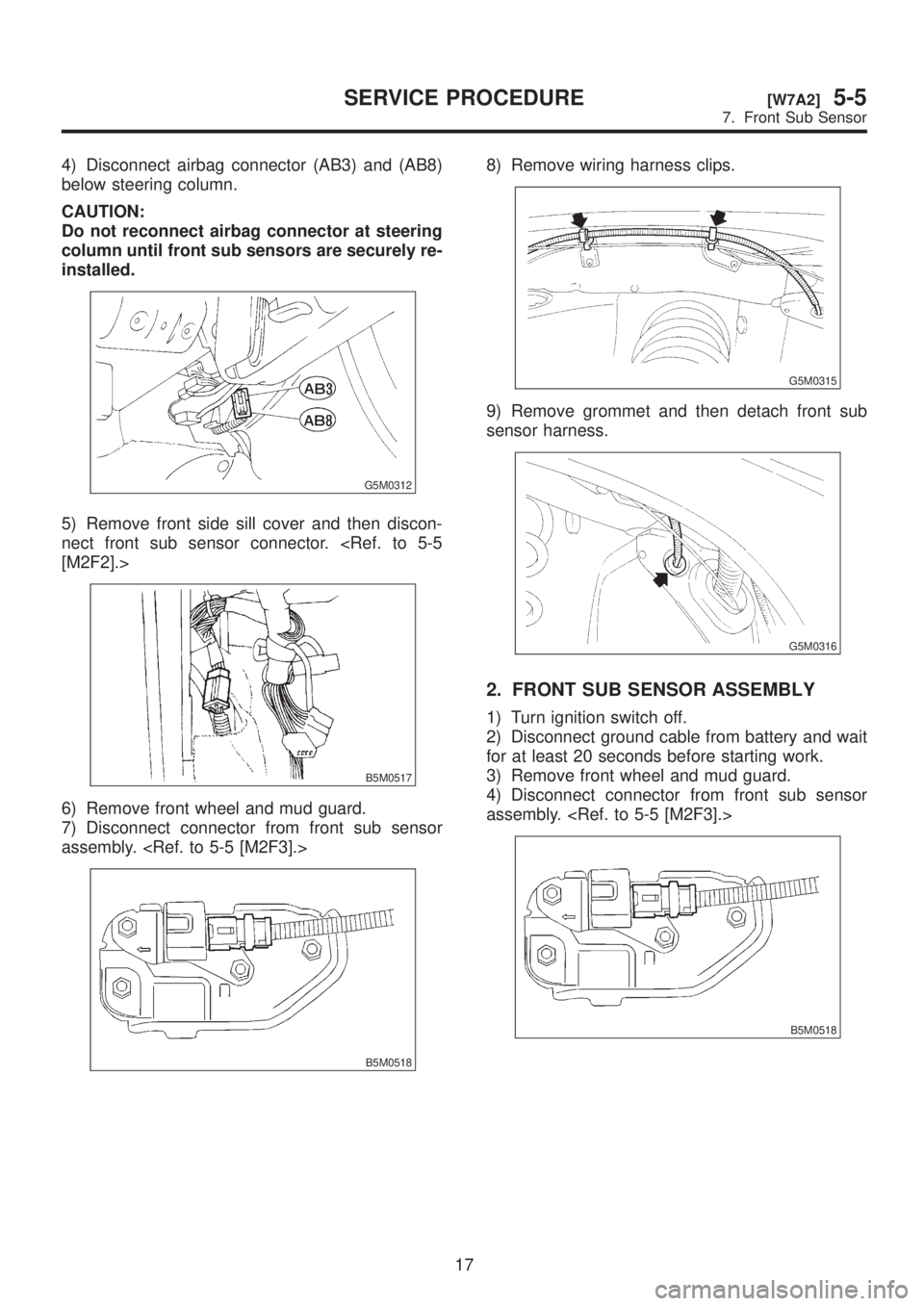
4) Disconnect airbag connector (AB3) and (AB8)
below steering column.
CAUTION:
Do not reconnect airbag connector at steering
column until front sub sensors are securely re-
installed.
G5M0312
5) Remove front side sill cover and then discon-
nect front sub sensor connector.
B5M0517
6) Remove front wheel and mud guard.
7) Disconnect connector from front sub sensor
assembly.
B5M0518
8) Remove wiring harness clips.
G5M0315
9) Remove grommet and then detach front sub
sensor harness.
G5M0316
2. FRONT SUB SENSOR ASSEMBLY
1) Turn ignition switch off.
2) Disconnect ground cable from battery and wait
for at least 20 seconds before starting work.
3) Remove front wheel and mud guard.
4) Disconnect connector from front sub sensor
assembly.
B5M0518
17
[W7A2]5-5SERVICE PROCEDURE
7. Front Sub Sensor
Page 1232 of 1456
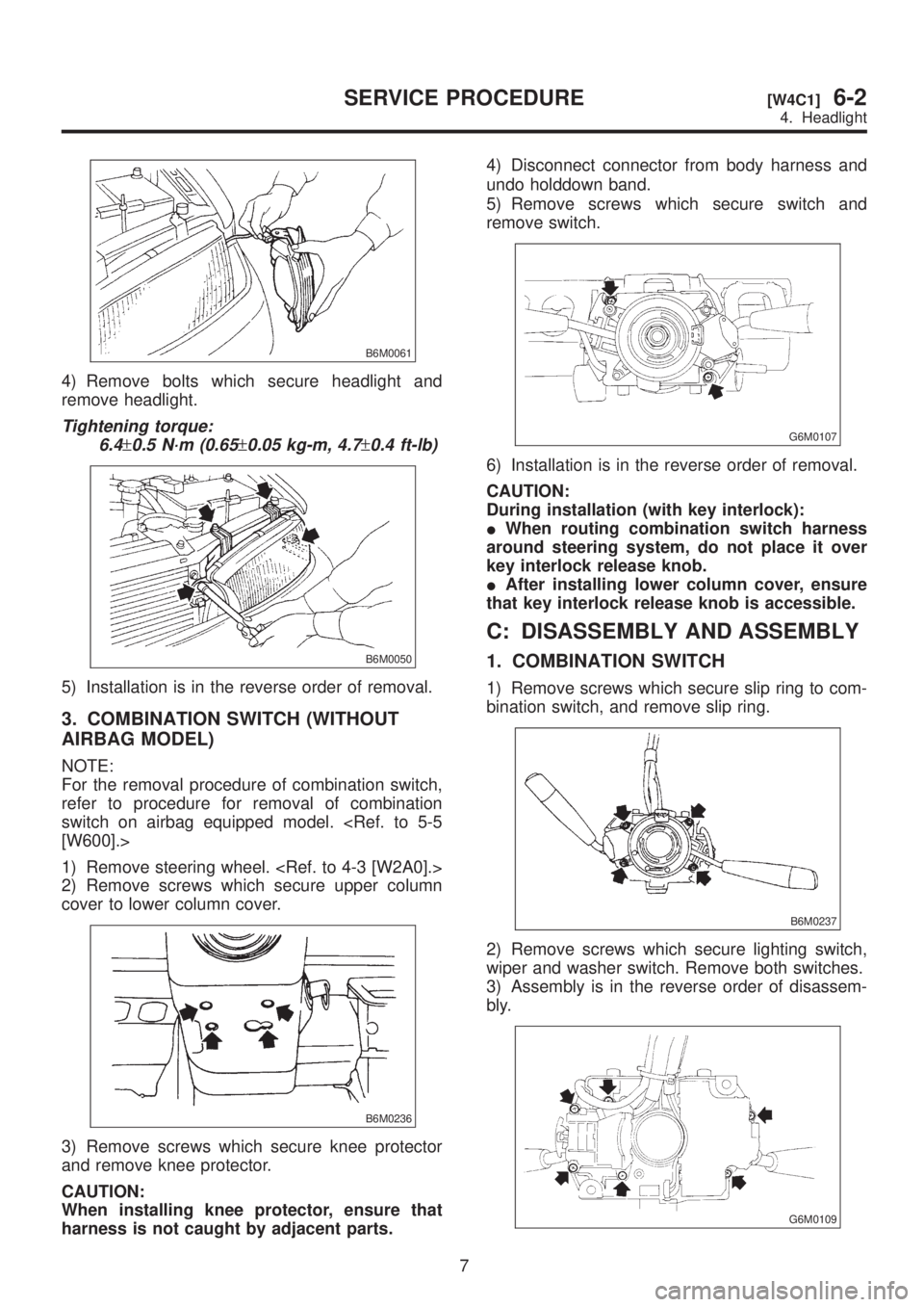
B6M0061
4) Remove bolts which secure headlight and
remove headlight.
Tightening torque:
6.4
±0.5 N´m (0.65±0.05 kg-m, 4.7±0.4 ft-lb)
B6M0050
5) Installation is in the reverse order of removal.
3. COMBINATION SWITCH (WITHOUT
AIRBAG MODEL)
NOTE:
For the removal procedure of combination switch,
refer to procedure for removal of combination
switch on airbag equipped model.
1) Remove steering wheel.
2) Remove screws which secure upper column
cover to lower column cover.
B6M0236
3) Remove screws which secure knee protector
and remove knee protector.
CAUTION:
When installing knee protector, ensure that
harness is not caught by adjacent parts.4) Disconnect connector from body harness and
undo holddown band.
5) Remove screws which secure switch and
remove switch.
G6M0107
6) Installation is in the reverse order of removal.
CAUTION:
During installation (with key interlock):
IWhen routing combination switch harness
around steering system, do not place it over
key interlock release knob.
IAfter installing lower column cover, ensure
that key interlock release knob is accessible.
C: DISASSEMBLY AND ASSEMBLY
1. COMBINATION SWITCH
1) Remove screws which secure slip ring to com-
bination switch, and remove slip ring.
B6M0237
2) Remove screws which secure lighting switch,
wiper and washer switch. Remove both switches.
3) Assembly is in the reverse order of disassem-
bly.
G6M0109
7
[W4C1]6-2SERVICE PROCEDURE
4. Headlight
Page 1255 of 1456
14. Combination Meter
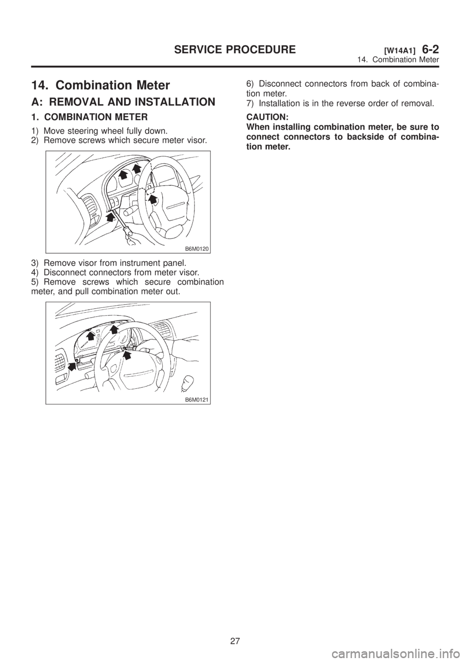
A: REMOVAL AND INSTALLATION
1. COMBINATION METER
1) Move steering wheel fully down.
2) Remove screws which secure meter visor.
B6M0120
3) Remove visor from instrument panel.
4) Disconnect connectors from meter visor.
5) Remove screws which secure combination
meter, and pull combination meter out.
B6M0121
6) Disconnect connectors from back of combina-
tion meter.
7) Installation is in the reverse order of removal.
CAUTION:
When installing combination meter, be sure to
connect connectors to backside of combina-
tion meter.
27
[W14A1]6-2SERVICE PROCEDURE
14. Combination Meter
Page 1258 of 1456

16. Horn and Cigarette Lighter
A: REMOVAL AND INSTALLATION
1. HORN
1) Open the engine hood.
2) Disconnect connector of horn.
3) Remove the horn.
4) Installation is in the reverse order of removal.
Tightening torque:
18
±5 N´m (1.8±0.5 kg-m, 13.0±3.6 ft-lb)
CAUTION:
After installing horn, connect connector, fit
firmly wiring harness to prevent from discon-
necting due to vibration.
B6M0349
2. HORN SWITCH (HORN PAD)
1) Remove screw which secures horn switch
(steering pad) to the base of steering wheel.
B6M0124
2) Remove horn switch (steering pad) from steer-
ing wheel while disconnecting connector.
3) Installation is in the reverse order of removal.
3. CIGARETTE LIGHTER
1) Remove center panel from instrument panel.
2) Disconnect connector from cigarette lighter.
3) Turn illumination socket 45É counterclockwise
and remove it.4) Loosen nut, and then remove cigarette lighter
body.
B6M0350A
5) Installation is in the reverse order of removal.
CAUTION:
IAlign socket with cutout portion of instru-
ment panel during installation.
IIn case of replacing cigarette lighter, use
genuine part only and always replace both plug
and socket combination.
B: INSPECTION
1. HORN SWITCH
Ensure that horn switch is free from the following
defects:
(1) Burned or shorted contacts
(2) Broken or weak spring
(3) Damaged harness
(4) Worn or corroded mating surface of horn plate
2. HORN RELAY
Check continuity between terminals as indicated in
table, when connecting the battery to terminals No.
1 and No. 2.
When current flows. Between termi-
nals No. 2 and
No. 3Continuity
exists.
When current does not
flow.Between termi-
nals No. 2 and
No. 3Continuity does
not exist.
Between termi-
nals No. 1 and
No. 2Continuity
exists.
B6M0126A
30
6-2[W16A1]SERVICE PROCEDURE
16. Horn and Cigarette Lighter
Page 1272 of 1456
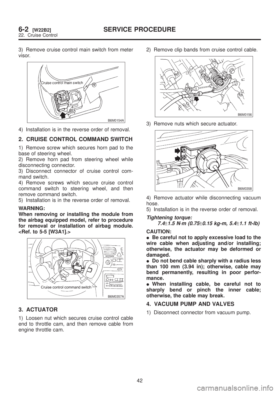
3) Remove cruise control main switch from meter
visor.
B6M0154A
4) Installation is in the reverse order of removal.
2. CRUISE CONTROL COMMAND SWITCH
1) Remove screw which secures horn pad to the
base of steering wheel.
2) Remove horn pad from steering wheel while
disconnecting connector.
3) Disconnect connector of cruise control com-
mand switch.
4) Remove screws which secure cruise control
command switch to steering wheel, and then
remove command switch.
5) Installation is in the reverse order of removal.
WARNING:
When removing or installing the module from
the airbag equipped model, refer to procedure
for removal or installation of airbag module.
B6M0357A
3. ACTUATOR
1) Loosen nut which secures cruise control cable
end to throttle cam, and then remove cable from
engine throttle cam.2) Remove clip bands from cruise control cable.
B6M0156
3) Remove nuts which secure actuator.
B6M0358
4) Remove actuator while disconnecting vacuum
hose.
5) Installation is in the reverse order of removal.
Tightening torque:
7.4
±1.5 N´m (0.75±0.15 kg-m, 5.4±1.1 ft-lb)
CAUTION:
IBe careful not to apply excessive load to the
wire cable when adjusting and/or installing;
otherwise, the actuator may be deformed or
damaged.
IDo not bend cable sharply with a radius less
than 100 mm (3.94 in); otherwise, cable may
bend permanently, resulting in poor perfor-
mance.
IWhen installing cable, be careful not to
sharply bend or pinch the inner cable;
otherwise, the cable may break.
4. VACUUM PUMP AND VALVES
1) Disconnect connector from vacuum pump.
42
6-2[W22B2]SERVICE PROCEDURE
22. Cruise Control