wheel SUBARU LEGACY 1999 Service Repair Manual
[x] Cancel search | Manufacturer: SUBARU, Model Year: 1999, Model line: LEGACY, Model: SUBARU LEGACY 1999Pages: 1456, PDF Size: 59.93 MB
Page 860 of 1456
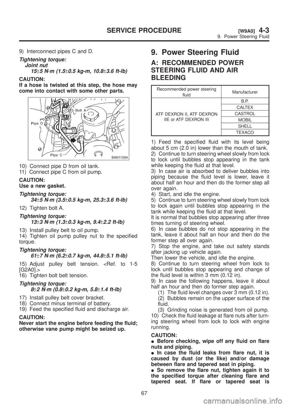
9) Interconnect pipes C and D.
Tightening torque:
Joint nut
15
±5 N´m (1.5±0.5 kg-m, 10.8±3.6 ft-lb)
CAUTION:
If a hose is twisted at this step, the hose may
come into contact with some other parts.
B4M1159A
10) Connect pipe D from oil tank.
11) Connect pipe C from oil pump.
CAUTION:
Use a new gasket.
Tightening torque:
34
±5 N´m (3.5±0.5 kg-m, 25.3±3.6 ft-lb)
12) Tighten bolt A.
Tightening torque:
13
±3 N´m (1.3±0.3 kg-m, 9.4±2.2 ft-lb)
13) Install pulley belt to oil pump.
14) Tighten oil pump pulley nut to the specified
torque.
Tightening torque:
61
±7 N´m (6.2±0.7 kg-m, 44.8±5.1 ft-lb)
15) Adjust pulley belt tension.
16) Tighten bolt belt tension.
Tightening torque:
8
±2 N´m (0.8±0.2 kg-m, 5.8±1.4 ft-lb)
17) Install pulley belt cover bracket.
18) Connect minus terminal of battery.
19) Feed the specified fluid and discharge air.
CAUTION:
Never start the engine before feeding the fluid;
otherwise vane pump might be seized up.
9. Power Steering Fluid
A: RECOMMENDED POWER
STEERING FLUID AND AIR
BLEEDING
Recommended power steering
fluidManufacturer
ATF DEXRON II, ATF DEXRON
IIE or ATF DEXRON IIIB.P.
CALTEX
CASTROL
MOBIL
SHELL
TEXACO
1) Feed the specified fluid with its level being
about 5 cm (2.0 in) lower than the mouth of tank.
2) Continue to turn steering wheel slowly from lock
to lock until bubbles stop appearing in the tank
while keeping the fluid at that level.
3) In case air is absorbed to deliver bubbles into
piping because the fluid level is lower, leave it
about half an hour and then do the former step all
over again.
4) Start, and idle the engine.
5) Continue to turn steering wheel slowly from lock
to lock again until bubbles stop appearing in the
tank while keeping the fluid at that level.
It is normal that bubbles stop appearing after three
times turning of steering wheel.
6) In case bubbles do not stop appearing in the
tank, leave it about half an hour and then do the
former step all over again.
7) Stop the engine, and take out safety stands
after jacking up vehicle again.
Then lower the vehicle, and idle the engine.
8) Continue to turn steering wheel from lock to
lock until bubbles stop appearing and change of
the fluid level is within 3 mm (0.12 in).
9) In case the following happens, leave it about
half an hour and then do former step again.
(1) The fluid level changes over 3 mm (0.12 in).
(2) Bubbles remain on the upper surface of the
fluid.
(3) Grinding noise is generated from oil pump.
10) Check the fluid leakage at flare nuts after turn-
ing steering wheel from lock to lock with engine
running.
CAUTION:
IBefore checking, wipe off any fluid on flare
nuts and piping.
IIn case the fluid leaks from flare nut, it is
caused by dust (or the like) and/or damage
between flare and tapered seat in piping.
ISo remove the flare nut, tighten again it to
the specified torque after cleaning flare and
tapered seat. If flare or tapered seat is
67
[W9A0]4-3SERVICE PROCEDURE
9. Power Steering Fluid
Page 861 of 1456
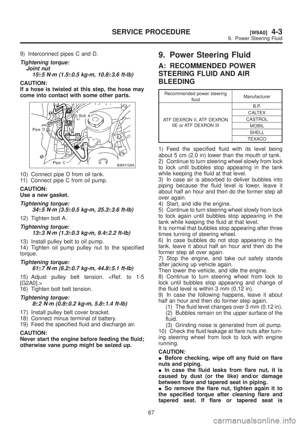
9) Interconnect pipes C and D.
Tightening torque:
Joint nut
15
±5 N´m (1.5±0.5 kg-m, 10.8±3.6 ft-lb)
CAUTION:
If a hose is twisted at this step, the hose may
come into contact with some other parts.
B4M1159A
10) Connect pipe D from oil tank.
11) Connect pipe C from oil pump.
CAUTION:
Use a new gasket.
Tightening torque:
34
±5 N´m (3.5±0.5 kg-m, 25.3±3.6 ft-lb)
12) Tighten bolt A.
Tightening torque:
13
±3 N´m (1.3±0.3 kg-m, 9.4±2.2 ft-lb)
13) Install pulley belt to oil pump.
14) Tighten oil pump pulley nut to the specified
torque.
Tightening torque:
61
±7 N´m (6.2±0.7 kg-m, 44.8±5.1 ft-lb)
15) Adjust pulley belt tension.
16) Tighten bolt belt tension.
Tightening torque:
8
±2 N´m (0.8±0.2 kg-m, 5.8±1.4 ft-lb)
17) Install pulley belt cover bracket.
18) Connect minus terminal of battery.
19) Feed the specified fluid and discharge air.
CAUTION:
Never start the engine before feeding the fluid;
otherwise vane pump might be seized up.
9. Power Steering Fluid
A: RECOMMENDED POWER
STEERING FLUID AND AIR
BLEEDING
Recommended power steering
fluidManufacturer
ATF DEXRON II, ATF DEXRON
IIE or ATF DEXRON IIIB.P.
CALTEX
CASTROL
MOBIL
SHELL
TEXACO
1) Feed the specified fluid with its level being
about 5 cm (2.0 in) lower than the mouth of tank.
2) Continue to turn steering wheel slowly from lock
to lock until bubbles stop appearing in the tank
while keeping the fluid at that level.
3) In case air is absorbed to deliver bubbles into
piping because the fluid level is lower, leave it
about half an hour and then do the former step all
over again.
4) Start, and idle the engine.
5) Continue to turn steering wheel slowly from lock
to lock again until bubbles stop appearing in the
tank while keeping the fluid at that level.
It is normal that bubbles stop appearing after three
times turning of steering wheel.
6) In case bubbles do not stop appearing in the
tank, leave it about half an hour and then do the
former step all over again.
7) Stop the engine, and take out safety stands
after jacking up vehicle again.
Then lower the vehicle, and idle the engine.
8) Continue to turn steering wheel from lock to
lock until bubbles stop appearing and change of
the fluid level is within 3 mm (0.12 in).
9) In case the following happens, leave it about
half an hour and then do former step again.
(1) The fluid level changes over 3 mm (0.12 in).
(2) Bubbles remain on the upper surface of the
fluid.
(3) Grinding noise is generated from oil pump.
10) Check the fluid leakage at flare nuts after turn-
ing steering wheel from lock to lock with engine
running.
CAUTION:
IBefore checking, wipe off any fluid on flare
nuts and piping.
IIn case the fluid leaks from flare nut, it is
caused by dust (or the like) and/or damage
between flare and tapered seat in piping.
ISo remove the flare nut, tighten again it to
the specified torque after cleaning flare and
tapered seat. If flare or tapered seat is
67
[W9A0]4-3SERVICE PROCEDURE
9. Power Steering Fluid
Page 863 of 1456
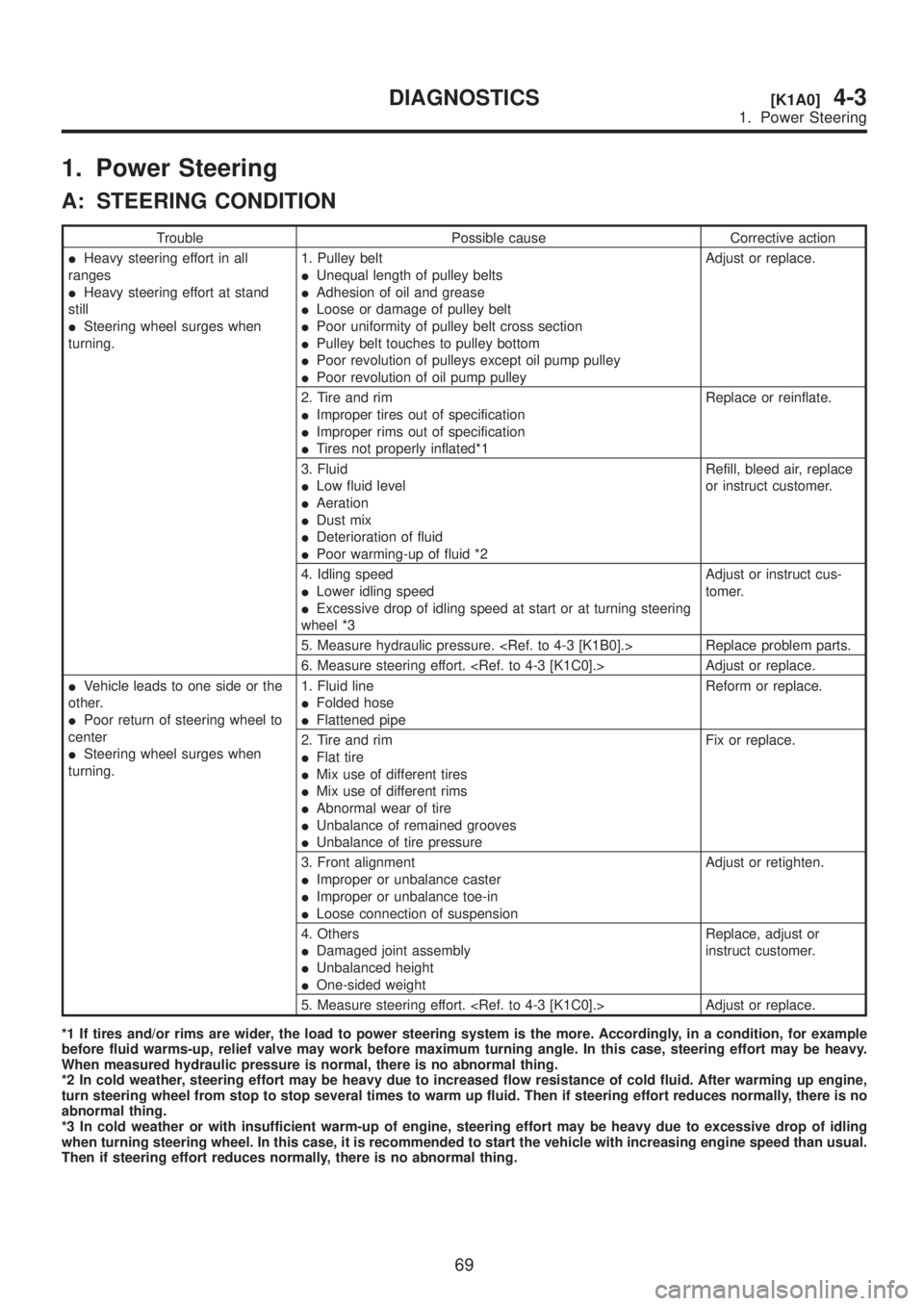
1. Power Steering
A: STEERING CONDITION
Trouble Possible cause Corrective action
IHeavy steering effort in all
ranges
IHeavy steering effort at stand
still
ISteering wheel surges when
turning.1. Pulley belt
IUnequal length of pulley belts
IAdhesion of oil and grease
ILoose or damage of pulley belt
IPoor uniformity of pulley belt cross section
IPulley belt touches to pulley bottom
IPoor revolution of pulleys except oil pump pulley
IPoor revolution of oil pump pulleyAdjust or replace.
2. Tire and rim
IImproper tires out of specification
IImproper rims out of specification
ITires not properly inflated*1Replace or reinflate.
3. Fluid
ILow fluid level
IAeration
IDust mix
IDeterioration of fluid
IPoor warming-up of fluid *2Refill, bleed air, replace
or instruct customer.
4. Idling speed
ILower idling speed
IExcessive drop of idling speed at start or at turning steering
wheel *3Adjust or instruct cus-
tomer.
5. Measure hydraulic pressure.
6. Measure steering effort.
IVehicle leads to one side or the
other.
IPoor return of steering wheel to
center
ISteering wheel surges when
turning.1. Fluid line
IFolded hose
IFlattened pipeReform or replace.
2. Tire and rim
IFlat tire
IMix use of different tires
IMix use of different rims
IAbnormal wear of tire
IUnbalance of remained grooves
IUnbalance of tire pressureFix or replace.
3. Front alignment
IImproper or unbalance caster
IImproper or unbalance toe-in
ILoose connection of suspensionAdjust or retighten.
4. Others
IDamaged joint assembly
IUnbalanced height
IOne-sided weightReplace, adjust or
instruct customer.
5. Measure steering effort.
*1 If tires and/or rims are wider, the load to power steering system is the more. Accordingly, in a condition, for example
before fluid warms-up, relief valve may work before maximum turning angle. In this case, steering effort may be heavy.
When measured hydraulic pressure is normal, there is no abnormal thing.
*2 In cold weather, steering effort may be heavy due to increased flow resistance of cold fluid. After warming up engine,
turn steering wheel from stop to stop several times to warm up fluid. Then if steering effort reduces normally, there is no
abnormal thing.
*3 In cold weather or with insufficient warm-up of engine, steering effort may be heavy due to excessive drop of idling
when turning steering wheel. In this case, it is recommended to start the vehicle with increasing engine speed than usual.
Then if steering effort reduces normally, there is no abnormal thing.
69
[K1A0]4-3DIAGNOSTICS
1. Power Steering
Page 864 of 1456
B: MEASUREMENT OF HYDRAULIC
PRESSURE
CAUTION:
IBe sure to complete all items aforemen-
tioned in ªSTEERING CONDITIONº, prior to
measuring hydraulic pressure. Otherwise,
pressure can not be measured correctly.
IDo not leave the valve of pressure gauge
closed or hold the steering wheel at stop end
for 5 seconds or more in any case, as the oil
pump may be damaged due to long keep of
these conditions.
IPut cotton cloth waste at a place where fluid
drops before pressure gauge is installed. Wipe
off split fluid thoroughly after the measure-
ment.
NOTE:
Keep engine idling during the measurement.
1B1 : MEASURE REGULAR PRESSURE.
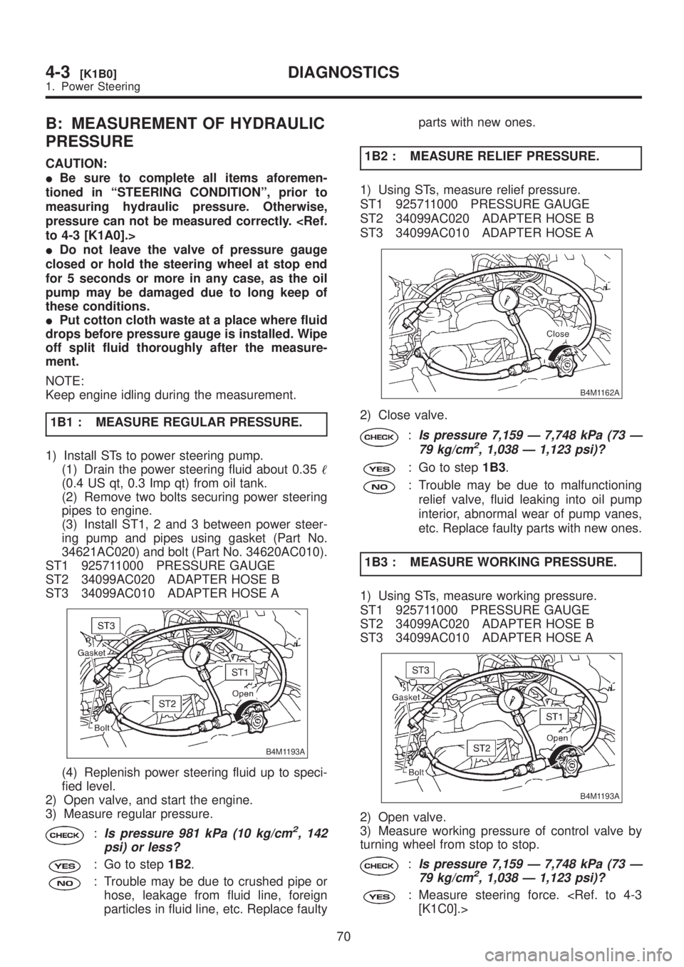
1) Install STs to power steering pump.
(1) Drain the power steering fluid about 0.35
(0.4 US qt, 0.3 Imp qt) from oil tank.
(2) Remove two bolts securing power steering
pipes to engine.
(3) Install ST1, 2 and 3 between power steer-
ing pump and pipes using gasket (Part No.
34621AC020) and bolt (Part No. 34620AC010).
ST1 925711000 PRESSURE GAUGE
ST2 34099AC020 ADAPTER HOSE B
ST3 34099AC010 ADAPTER HOSE A
B4M1193A
(4) Replenish power steering fluid up to speci-
fied level.
2) Open valve, and start the engine.
3) Measure regular pressure.
:Is pressure 981 kPa (10 kg/cm2, 142
psi) or less?
: Go to step1B2.
: Trouble may be due to crushed pipe or
hose, leakage from fluid line, foreign
particles in fluid line, etc. Replace faultyparts with new ones.
1B2 : MEASURE RELIEF PRESSURE.
1) Using STs, measure relief pressure.
ST1 925711000 PRESSURE GAUGE
ST2 34099AC020 ADAPTER HOSE B
ST3 34099AC010 ADAPTER HOSE A
B4M1162A
2) Close valve.
:Is pressure 7,159 Ð 7,748 kPa (73 Ð
79 kg/cm2, 1,038 Ð 1,123 psi)?
: Go to step1B3.
: Trouble may be due to malfunctioning
relief valve, fluid leaking into oil pump
interior, abnormal wear of pump vanes,
etc. Replace faulty parts with new ones.
1B3 : MEASURE WORKING PRESSURE.
1) Using STs, measure working pressure.
ST1 925711000 PRESSURE GAUGE
ST2 34099AC020 ADAPTER HOSE B
ST3 34099AC010 ADAPTER HOSE A
B4M1193A
2) Open valve.
3) Measure working pressure of control valve by
turning wheel from stop to stop.
:Is pressure 7,159 Ð 7,748 kPa (73 Ð
79 kg/cm2, 1,038 Ð 1,123 psi)?
: Measure steering force.
70
4-3[K1B0]DIAGNOSTICS
1. Power Steering
Page 868 of 1456
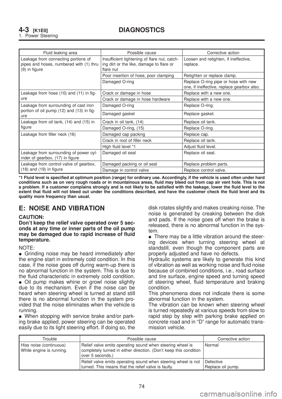
Fluid leaking area Possible cause Corrective action
Leakage from connecting portions of
pipes and hoses, numbered with (1) thru
(9) in figureInsufficient tightening of flare nut, catch-
ing dirt or the like, damage to flare or
flare nutLoosen and retighten, if ineffective,
replace.
Poor insertion of hose, poor clamping Retighten or replace clamp.
Damaged O-ring Replace O-ring pipe or hose with new
one, if ineffective, replace gearbox also.
Leakage from hose (10) and (11) in fig-
ureCrack or damage in hose Replace with a new one.
Crack or damage in hose hardware Replace with a new one.
Leakage from surrounding of cast iron
portion of oil pump (12) and (13) in fig-
ureDamaged O-ring Replace O-ring.
Damaged gasket Replace gasket.
Leakage from oil tank, (14) and (15) in
figureCrack in oil tank, (14) Replace oil tank.
Damaged O-ring, (15) Replace O-ring.
Leakage from filler neck (16) Damaged cap packing Replace cap.
Crack in root of filler neck Replace oil tank.
High fluid level *1 Adjust fluid level.
Leakage from surrounding of power cyl-
inder of gearbox, (17) in figureDamaged oil seal Replace oil seal.
Leakage from control valve of gearbox,
(18) and (19) in figureDamaged packing or oil seal Replace problem parts.
Damage in control valve Replace control valve.
*1 Fluid level is specified at optimum position (range) for ordinary use. Accordingly, if the vehicle is used often under hard
conditions such as on very rough roads or in mountainous areas, fluid may bleed out from cap air vent hole. This is not
a problem. If a customer complains strongly and is not likely to be satisfied with the leakage, lower the fluid level to the
extent that fluid will not bleed out under the conditions described, and have the customer check the fluid level and its
quality more frequency than usual.
E: NOISE AND VIBRATION
CAUTION:
Don't keep the relief valve operated over 5 sec-
onds at any time or inner parts of the oil pump
may be damaged due to rapid increase of fluid
temperature.
NOTE:
IGrinding noise may be heard immediately after
the engine start in extremely cold condition. In this
case, if the noise goes off during warm-up there is
no abnormal function in the system. This is due to
the fluid characteristic in extremely cold condition.
IOil pump makes whine or growl noise slightly
due to its mechanism. Even if the noise can be
heard when steering wheel is turned at stand still
there is no abnormal function in the system pro-
vided that the noise eliminates when the vehicle is
running.
IWhen stopping with service brake and/or park-
ing brake applied, power steering can be operated
easily due to its light steering effort. If doing so, thedisk rotates slightly and makes creaking noise. The
noise is generated by creaking between the disk
and pads. If the noise goes off when the brake is
released, there is no abnormal function in the sys-
tem.
IThere may be a little vibration around the steer-
ing devices when turning steering wheel at
standstill, even though the component parts are
properly adjusted and have no defects.
Hydraulic systems are likely to generate this kind
of vibration as well as working noise and fluid noise
because of combined conditions, i.e., road surface
and tire surface, engine speed and turning speed
of steering wheel, fluid temperature and braking
condition.
This phenomena does not indicate there is some
abnormal function in the system.
The vibration can be known when steering wheel
is turned repeatedly at various speeds from slow to
rapid step by step with parking brake applied on
concrete road and in ªDº range for automatic trans-
mission vehicle.
Trouble Possible cause Corrective action
Hiss noise (continuous)
While engine is running.Relief valve emits operating sound when steering wheel is
completely turned in either direction. (Don't keep this condition
over 5 seconds.)Normal
Relief valve emits operating sound when steering wheel is not
turned. This means that the relief valve is faulty.Defective
Replace oil pump.
74
4-3[K1E0]DIAGNOSTICS
1. Power Steering
Page 869 of 1456
![SUBARU LEGACY 1999 Service Repair Manual Trouble Possible cause Corrective action
Rattling noise (intermittent)
While engine is running.Interference with adjacent parts Check clearance.
Correct if necessary.
<Ref. to 4-3 [K1F0].>
Loosened in](/img/17/57435/w960_57435-868.png "SUBARU LEGACY 1999 Service Repair Manual Trouble Possible cause Corrective action
Rattling noise (intermittent)
While engine is running.Interference with adjacent parts Check clearance.
Correct if necessary.
<Ref. to 4-3 [K1F0].>
Loosened in")
Trouble Possible cause Corrective action
Rattling noise (intermittent)
While engine is running.Interference with adjacent parts Check clearance.
Correct if necessary.
Loosened installation of oil pump, oil tank, pump bracket, gear-
box or crossmemberRetighten.
Loosened installation of oil pump pulley or other pulley(s) Retighten.
Loosened linkage or play of steering or suspension
Loosened tightening of joint or steering columnRetighten or replace.
Sound generates from the inside of gearbox or oil pump. Replace the gearbox or oil
pump.
Knocking
When turning steering wheel
in both direction with small
angle repeatedly at engine
ON or OFF.Excessive backlash
Loosened lock nut for adjusting backlashAdjust and retighten.
Loosened tightening or play of tie-rod, tie-rod end Retighten or replace.
Grinding noise (continuous)
While engine is running.Vane pump aeration Inspect and retighten fluid line
connection.
Refill fluid and vent air.
Vane pump seizing Replace oil pump.
Pulley bearing seizing of oil pump Replace oil pump.
Folded hose, flat pipe Replace.
Squeal, squeak (intermittent
or continuous)
While engine is running.Maladjustment of pulley belt
Damaged or charged pulley belt
Unequal length of pulley beltsAdjust or replace.
(Replace two belts as a set.)
Run out or soilage of V-groove surface of oil pump pulley Clean or replace.
Sizzling noise (continuous)
While engine is running.Fluid aeration Fix wrong part causing aera-
tion.
Replace fluid and vent air.
Damaged pipe of gearbox Replace pipe.
Abnormal inside of hose or pipe
Flat hose or pipeRectify or replace.
Abnormal inside of oil tank Replace.
Removed oil tank cap Install cap.
Whistle (continuous)
While engine is running.Abnormal pipe of gearbox or abnormal inside of hose Replace bad parts of gearbox
or hose.
Whine or growl (continuous or
intermittent)
While engine is running with/
without steering turned.Loosened installation of oil pump, oil pump bracket Retighten.
Abnormal inside of oil pump, hose Replace oil pump, hose, if the
noise can be heard when run-
ning as well as stand still.
Torque converter growl air conditioner compression growl Remove power steering pul-
ley belt and confirm.
Creaking noise (intermittent)
While engine is running with
steering turned.Abnormal inside of gearbox Replace bad parts of gear-
box.
Abnormal bearing for steering shaft Apply grease or replace.
Generates when turning steering wheel with brake (service or
parking) applied.If the noise goes off when
brake is released, it is normal.
Vibration
While engine is running with/
without steering turned.Too low engine speed at start Adjust and instruct custom-
ers.
Vane pump aeration Fix wrong part.
Vent air.
Damaged valve in oil pump, gearbox Replace oil pump, bad parts
of gearbox.
Looseness of play of steering, suspension parts Retighten.
75
[K1E0]4-3DIAGNOSTICS
1. Power Steering
Page 880 of 1456
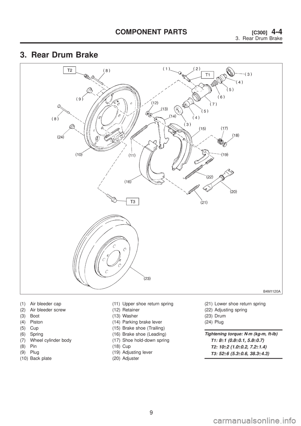
3. Rear Drum Brake
B4M1120A
(1) Air bleeder cap
(2) Air bleeder screw
(3) Boot
(4) Piston
(5) Cup
(6) Spring
(7) Wheel cylinder body
(8) Pin
(9) Plug
(10) Back plate(11) Upper shoe return spring
(12) Retainer
(13) Washer
(14) Parking brake lever
(15) Brake shoe (Trailing)
(16) Brake shoe (Leading)
(17) Shoe hold-down spring
(18) Cup
(19) Adjusting lever
(20) Adjuster(21) Lower shoe return spring
(22) Adjusting spring
(23) Drum
(24) Plug
Tightening torque: N´m (kg-m, ft-lb)
T1:
8±1 (0.8±0.1, 5.8±0.7)
T2:10±2 (1.0±0.2, 7.2±1.4)
T3:52±6 (5.3±0.6, 38.3±4.3)
9
[C300]4-4COMPONENT PARTS
3. Rear Drum Brake
Page 889 of 1456
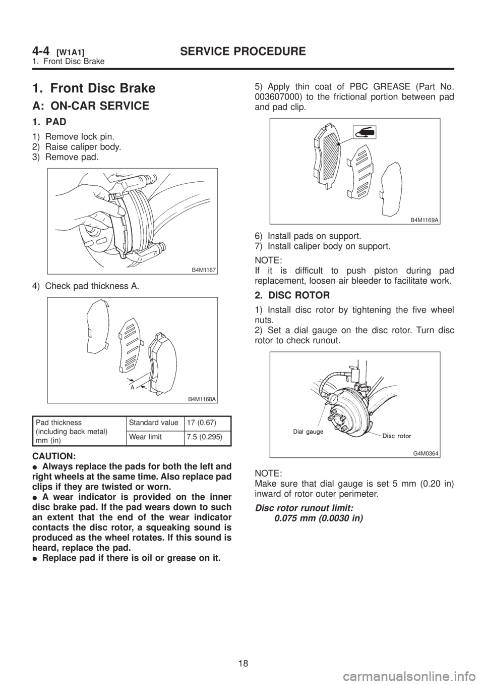
1. Front Disc Brake
A: ON-CAR SERVICE
1. PAD
1) Remove lock pin.
2) Raise caliper body.
3) Remove pad.
B4M1167
4) Check pad thickness A.
B4M1168A
Pad thickness
(including back metal)
mm (in)Standard value 17 (0.67)
Wear limit 7.5 (0.295)
CAUTION:
IAlways replace the pads for both the left and
right wheels at the same time. Also replace pad
clips if they are twisted or worn.
IA wear indicator is provided on the inner
disc brake pad. If the pad wears down to such
an extent that the end of the wear indicator
contacts the disc rotor, a squeaking sound is
produced as the wheel rotates. If this sound is
heard, replace the pad.
IReplace pad if there is oil or grease on it.5) Apply thin coat of PBC GREASE (Part No.
003607000) to the frictional portion between pad
and pad clip.
B4M1169A
6) Install pads on support.
7) Install caliper body on support.
NOTE:
If it is difficult to push piston during pad
replacement, loosen air bleeder to facilitate work.
2. DISC ROTOR
1) Install disc rotor by tightening the five wheel
nuts.
2) Set a dial gauge on the disc rotor. Turn disc
rotor to check runout.
G4M0364
NOTE:
Make sure that dial gauge is set 5 mm (0.20 in)
inward of rotor outer perimeter.
Disc rotor runout limit:
0.075 mm (0.0030 in)
18
4-4[W1A1]SERVICE PROCEDURE
1. Front Disc Brake
Page 895 of 1456
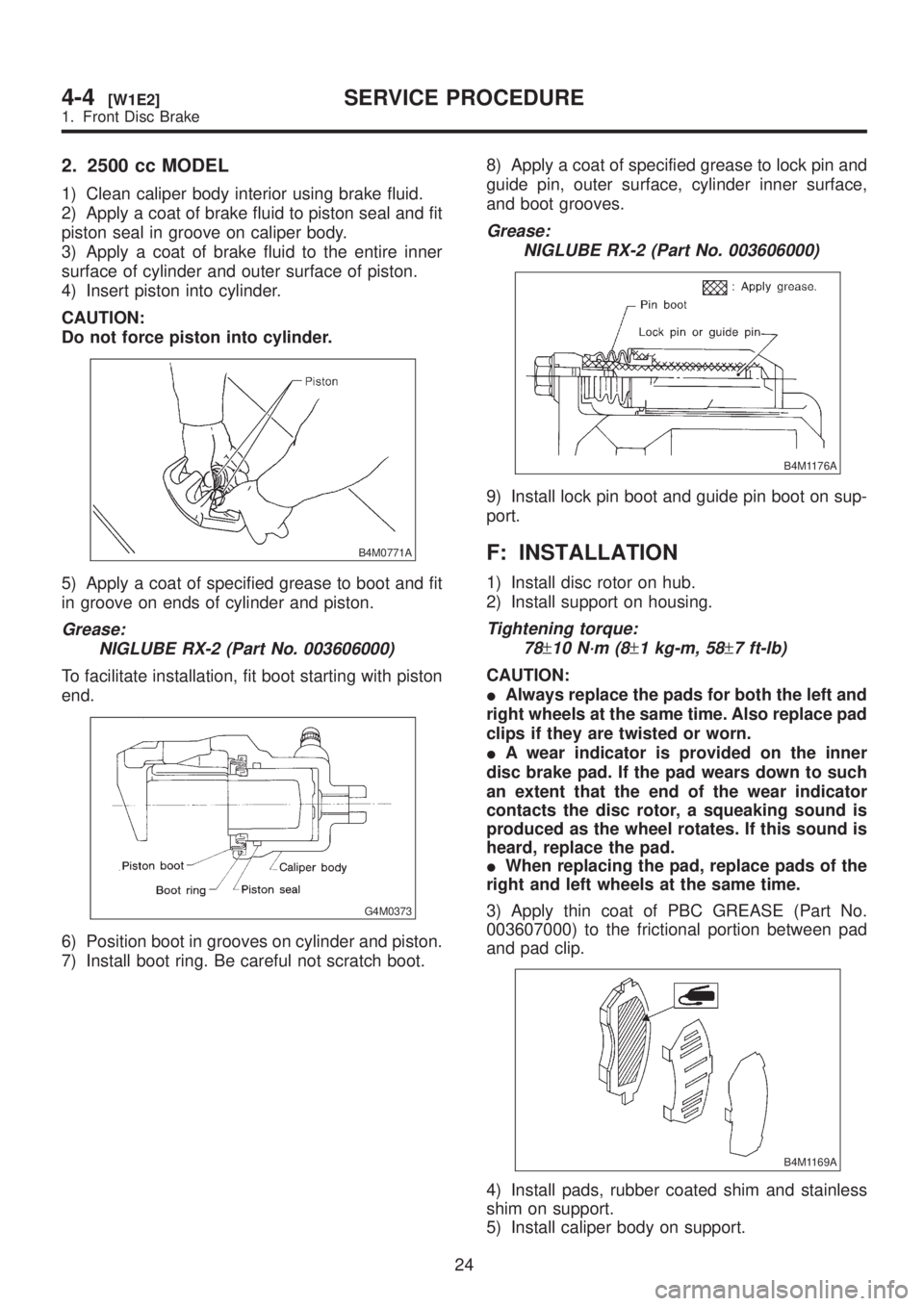
2. 2500 cc MODEL
1) Clean caliper body interior using brake fluid.
2) Apply a coat of brake fluid to piston seal and fit
piston seal in groove on caliper body.
3) Apply a coat of brake fluid to the entire inner
surface of cylinder and outer surface of piston.
4) Insert piston into cylinder.
CAUTION:
Do not force piston into cylinder.
B4M0771A
5) Apply a coat of specified grease to boot and fit
in groove on ends of cylinder and piston.
Grease:
NIGLUBE RX-2 (Part No. 003606000)
To facilitate installation, fit boot starting with piston
end.
G4M0373
6) Position boot in grooves on cylinder and piston.
7) Install boot ring. Be careful not scratch boot.8) Apply a coat of specified grease to lock pin and
guide pin, outer surface, cylinder inner surface,
and boot grooves.
Grease:
NIGLUBE RX-2 (Part No. 003606000)
B4M1176A
9) Install lock pin boot and guide pin boot on sup-
port.
F: INSTALLATION
1) Install disc rotor on hub.
2) Install support on housing.
Tightening torque:
78
±10 N´m (8±1 kg-m, 58±7 ft-lb)
CAUTION:
IAlways replace the pads for both the left and
right wheels at the same time. Also replace pad
clips if they are twisted or worn.
IA wear indicator is provided on the inner
disc brake pad. If the pad wears down to such
an extent that the end of the wear indicator
contacts the disc rotor, a squeaking sound is
produced as the wheel rotates. If this sound is
heard, replace the pad.
IWhen replacing the pad, replace pads of the
right and left wheels at the same time.
3) Apply thin coat of PBC GREASE (Part No.
003607000) to the frictional portion between pad
and pad clip.
B4M1169A
4) Install pads, rubber coated shim and stainless
shim on support.
5) Install caliper body on support.
24
4-4[W1E2]SERVICE PROCEDURE
1. Front Disc Brake
Page 898 of 1456
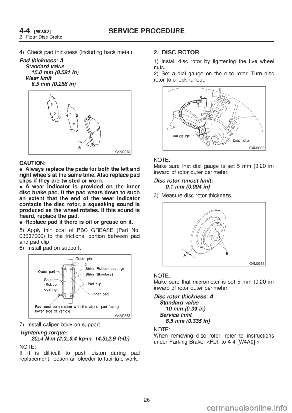
4) Check pad thickness (including back metal).
Pad thickness: A
Standard value
15.0 mm (0.591 in)
Wear limit
6.5 mm (0.256 in)
G4M0362
CAUTION:
IAlways replace the pads for both the left and
right wheels at the same time. Also replace pad
clips if they are twisted or worn.
IA wear indicator is provided on the inner
disc brake pad. If the pad wears down to such
an extent that the end of the wear indicator
contacts the disc rotor, a squeaking sound is
produced as the wheel rotates. If this sound is
heard, replace the pad.
IReplace pad if there is oil or grease on it.
5) Apply thin coat of PBC GREASE (Part No.
03607000) to the frictional portion between pad
and pad clip.
6) Install pad on support.
G4M0363
7) Install caliper body on support.
Tightening torque:
20
±4 N´m (2.0±0.4 kg-m, 14.5±2.9 ft-lb)
NOTE:
If it is difficult to push piston during pad
replacement, loosen air bleeder to facilitate work.
2. DISC ROTOR
1) Install disc rotor by tightening the five wheel
nuts.
2) Set a dial gauge on the disc rotor. Turn disc
rotor to check runout.
G4M0382
NOTE:
Make sure that dial gauge is set 5 mm (0.20 in)
inward of rotor outer perimeter.
Disc rotor runout limit:
0.1 mm (0.004 in)
3) Measure disc rotor thickness.
G4M0383
NOTE:
Make sure that micrometer is set 5 mm (0.20 in)
inward of rotor outer perimeter.
Disc rotor thickness: A
Standard value
10 mm (0.39 in)
Service limit
8.5 mm (0.335 in)
NOTE:
When removing disc rotor, refer to instructions
under Parking Brake.
26
4-4[W2A2]SERVICE PROCEDURE
2. Rear Disc Brake